Engine Room Ventilation System of Ship CFD Simulation
$100.00 Student Discount
- The problem numerically simulates the engine room ventilation system of a ship using ANSYS Fluent software.
- We design the 3-D model by the Design Modeler software.
- We Mesh the model by ANSYS Meshing software, and the element number equals 706053.
- Some energy sources are defined to determine the heat generation in diesel engines and motors.
Click on Add To Cart and obtain the Geometry file, Mesh file, and a Comprehensive ANSYS Fluent Training Video.
To Order Your Project or benefit from a CFD consultation, contact our experts via email ([email protected]), online support tab, or WhatsApp at +44 7443 197273.
There are some Free Products to check our service quality.
If you want the training video in another language instead of English, ask it via [email protected] after you buy the product.
Description
Engine Room Ventilation System of Ship, ANSYS Fluent CFD Simulation Training
This simulation is about a ship’s engine room ventilation system via ANSYS Fluent software.
On ships, the power needed to start compressors, pumps, fans, etc., is all supplied by electric motors. The engine room occupies the most significant space allocated to the various parts inside the ship.
Due to the accumulation of all these machines in this space, studying how heat is transferred is necessary.
The Optimal design of the air conditioning system to supply combustion air inside the equipment and regulate temperature and humidity inside this space is one of the most important points in the design of engine rooms and shipbuilding.
Engineers and researchers have always tried to optimize the air conditioning system’s design for ships by presenting new methods. Simulation and analysis of the ventilation system related to the ship’s engine room can help better explore new and innovative methods.
This project’s room consists of an air inlet (mass-flow type, 35 Kg/s) and two pressure outlets. The diesel engines and motors generate heat (12500 and 8333.333 W/m3, respectively) while working.
The injected air (300 K) is responsible for cooling the engine room and lowering the temperature of engines and motors.
The geometry of the present model is drawn by Design Modeler software. The model is then meshed by ANSYS Meshing software. The model mesh is unstructured, and 706053 cells have been created.
Engine Room Methodology
In this simulation, the energy model is activated because the primary goal of this project is heat transfer. A distinct volume is considered in the modeling to define the heat generated by motors and diesel engines. It is assumed that each volume produces a specific amount of heat.
A heat source must be defined in cell zone conditions to determine the amount of heat; That is, a certain amount of energy is produced per unit volume.
Engine Room Conclusion
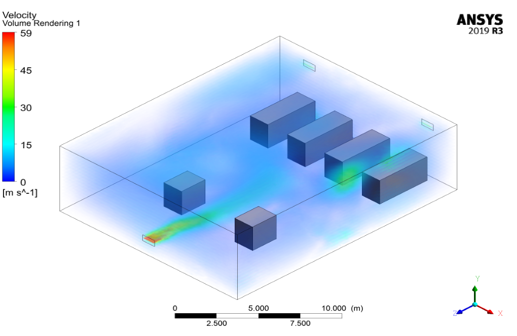
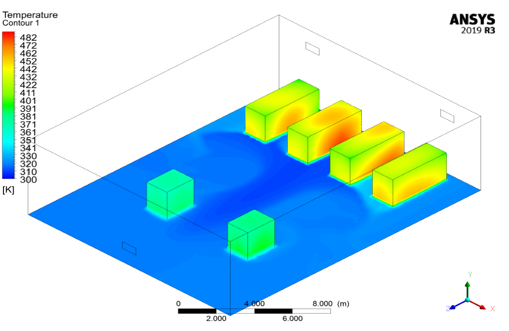
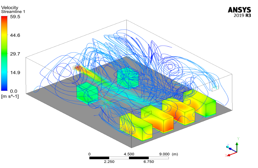
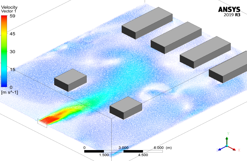
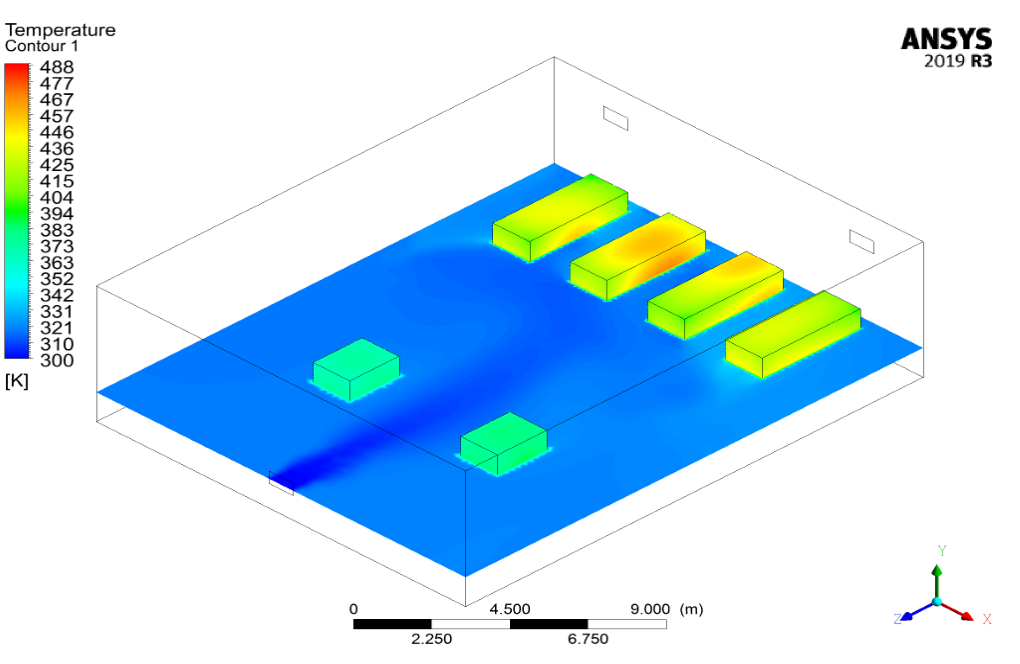
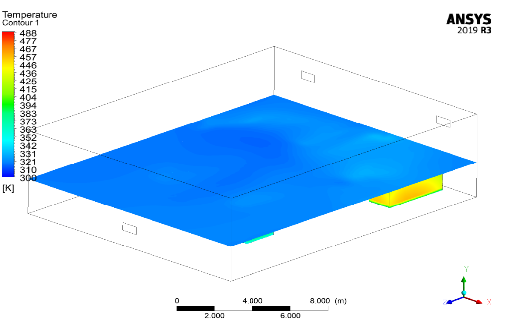
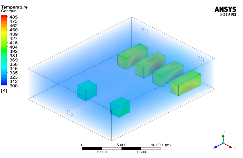
After simulation, the contours of temperature, velocity, and pressure are obtained. Also, streamline and velocity vectors are obtained. Streamlines indicate that the cooling air of the ventilation system enters the room and is well distributed in the space.
The temperature contour also shows that the motors and diesel engines have a high temperature, and cold air goes to the surface of the motors and engines to cool them.

Godfrey Wehner –
Is there a way for me to contribute to this simulation?
MR CFD Support –
We welcome contributions! Feel free to share your ideas or suggestions.
Rubie Dooley –
The level of detail in this simulation is truly impressive.
Magali Dickinson II –
The explanation of the engine room’s cooling process is excellent. This training must have been incredibly comprehensive and practical.
MR CFD Support –
Thank you for the kind words! We’re delighted to hear that our ANSYS Fluent CFD Simulation training for the engine room ventilation system met your expectations and provided comprehensive and practical knowledge. Your feedback is much appreciated, and it encourages us to continue delivering high-quality instructional content. If you have any further questions or need additional training materials, feel free to reach out!
Dolores Lebsack –
Fantastic simulation! Learning how to model the ventilation of such a complex system has been incredibly informative. The detailed results really help visualize the effectiveness of the ventilation design.
MR CFD Support –
We’re thrilled to hear that you found the simulation on engine room ventilation system helpful and educational! It’s great to know that the visualization of the results contributed to a better understanding of the ventilation design. Thank you for taking the time to share your positive experience with our CFD simulation training product.
Dianna Reinger PhD –
I used the Engine Room Ventilation System of Ship CFD Simulation and it was very comprehensive. I’ve learned a lot about engine room thermal management!
MR CFD Support –
Thank you for your positive feedback! We’re delighted to hear that our CFD Simulation provided you with valuable insights into the thermal management of a ship’s engine room. If you have any further inquiries or need additional support, please don’t hesitate to reach out.
Blanche Sanford –
What advantages does using CFD offer in analyzing engine room ventilation systems?
MR CFD Support –
CFD provides a detailed analysis of the airflow characteristics in engine room ventilation systems, offering insights that are difficult to obtain through experimental tests.
Dr. Judge Kreiger DVM –
I am so impressed with the engine room ventilation system simulation! The level of detail in mapping out heat transfer and air flow has provided extremely insightful data for optimizing our designs. The visualized temperature contours and streamline patterns were particularly helpful!
MR CFD Support –
Thank you for the positive feedback! We’re thrilled to hear that the ventilation system simulation for the engine room was not only insightful but also provided the visual tools needed to optimize your design. If you have further requirements or another project in mind, feel free to contact us. We’re here to assist with your CFD needs!
Bert Klein –
The detailed visualization of the results greatly aids in understanding the airflow in engine room ventilation systems.
Derek Wolff III –
The simulation sounds comprehensive. Would you be able to describe how the simulations account for the temperature difference throughout the engine room—like how it varies closer to the engines and further away in the corners?
MR CFD Support –
The temperature distribution throughout the engine room is calculated using the energy equation as part of the simulation. As the hot air emitted by the engines and motors rises, cooler air is brought in through the intake to replace it, resulting in a temperature gradient. Closer to the engines and motors, the temperature is higher and decreases as you move away. Detailed temperature contours generated by the simulation show this variation and allow understanding of how effectively the ventilation system cools different parts of the engine room.
Prof. Kaden Fritsch V –
Does the simulation take into account the natural convection that occurs in an actual engine room or is it purely focused on the forced ventilation system?
MR CFD Support –
In this simulation, the focus is primarily on the forced ventilation system to cool the engine room. Heat sources from motors and diesel engines are predefined and the simulation studies the effectiveness of the air conditioning system injected by the mass-flow inlet in reducing these temperatures. While the simulation includes heat transfer, which could include convective effects, the primary mechanism being modelled is forced convection through the ventilation system.
Ashleigh Mills –
The ability to customize this simulation for different types of ventilation systems is a significant advantage!