Project Outsourcing
Outsource your project to the MR CFD simulation engineering team. Our experts are ready to carry out every CFD project in all related engineering fields. Our services include industrial and academic purposes, considering the ANSYS Fluent software's wide range of CFD simulations. By outsourcing your project, you can benefit from MR CFD's primary services, including Consultation, Training, and CFD Simulation. The project freelancing procedure is as follows:
An official contract will be set based on your project description and details.
As we start your project, you will have access to our Portal to track its progress.
You will receive the project's resource files after you confirm the final report.
Finally, you will receive a comprehensive training video and technical support.
What is the Discrete Phase Model (DPM)?
The discrete Phase Model is a subsection of Multiphase flows. A discrete phase model (DPM) is used when the aim is to investigate the behavior of the particles from a Lagrangian view and a discrete perspective. The difference between the Lagrangian and the Eulerian view is that fluid behavior in the Lagrangian view is examined based on particle tracking of a particulate flow. In contrast, fluid behavior is considered in the Eulerian view based on the assumption of a finite volume element in the fluid flow path.
The Discrete Phase Model solves the continuous phase using Navier-Stokes equations. At the same time, the discrete phase is simulated by tracking many particles, bubbles, or droplets passing through the calculated continuous flow field. It should be noted that the discrete phase can exchange momentum, mass, and energy with the continuous phase. This method can be made much simpler by ignoring the interaction of particles (as well as droplets and bubbles) with each other. Of course, this can happen when the discrete phase, even with a large mass, has a much smaller volume (less than 10%) than the continuous phase. The particle paths are calculated and determined separately after each iteration of the continuous phase calculations.
The Discrete Phase Model (DPM) is a modeling tool used in Computational Fluid Dynamics (CFD) simulations to track the motion of discrete particles, such as droplets, bubbles, or solid particles, in a fluid flow. Discrete particles might include solid particles. Instead of describing the flow of the fluid itself, the dynamic particle model (DPM) takes a Lagrangian approach. This means that it tracks the motion of individual particles as they go through the fluid.
In discrete particle modeling (DPM), the particles are considered distinct entities that interact with the flow of the fluid through various forces such as lift, drag, and others. The motion of the particles is governed by equations of motion, which consider the forces acting on the particles, such as gravity, buoyancy, and fluid drag. These equations take into account the mobility of the particles.
Simulations of multiphase flows, particularly those in which the behavior of particles or droplets is significant, such as spray combustion, fluidized bed reactors, or particle-laden flows, frequently use DPM as the model of choice. DPM can offer precise information about the distribution, velocity, and trajectory of particles in a flow by tracking the motion of individual particles. This information can be utilized to optimize the Design and operation of industrial processes.
One of the shortcomings of DPM is that it does not consider the particles’ influence on the fluid flow, which, in certain circumstances, can have a substantial impact. DPM is frequently employed with other modeling strategies, such as Eulerian-Eulerian or Eulerian-Lagrangian approaches, which simultaneously describe the flow of fluid and particles to circumvent the limitations imposed by this method alone.
How can CFD simulation be applied in DPM Engineering Industries?
Newton’s second law of motion explains the basic theory behind the discrete phase modeling process. As was mentioned in the previous paragraph, the continuous phase equations are solved first to obtain the flow field and its related parameters. Then, based on different projects, one may assume various forces that apply to the particulate phase. Finally, we can track each particle inside our continuous phase by coupling the Navier-Stokes equations with Newton’s.
The Discrete Phase in ANSYS FLUENT can be used to model different types of phenomena, including:
- Calculation of the discrete phase trajectory using a Lagrangian formulation that includes the discrete phase inertia, hydrodynamic drag, and the force of gravity for both steady and unsteady flows
- prediction of the effects of turbulence on the dispersion of particles due to turbulent eddies present in the continuous phase
- heating/cooling of the discrete phase
- vaporization and boiling of liquid droplets
- combusting particles, including volatile evolution and char combustion, to simulate coal combustion
- droplet breakup and coalescence
- Erosion or accretion
- …
Various built-in forces can be applied to make the created Project even more realistic, such as Thermophoretic, Brownian, Saffman forces, etc. Also, user-defined functions are always there to model the forces not predefined in the software. These modeling capabilities allow ANSYS FLUENT to simulate various discrete phase problems, including particle separation and classification, spray drying, aerosol dispersion, bubble stirring of liquids, liquid fuel combustion, and coal combustion.
Simulations of Computational Fluid Dynamics (CFD) can be utilized in Discrete Phase description (DPM) engineering fields to describe and investigate the dynamics of particle-laden flows. DPM is a Lagrangian technique that models individual particles’ motion within a fluid flow. It is often used to mimic the behavior of dense particle-laden flows in industrial processes, such as fluidized bed reactors, cyclone separators, and pneumatic conveying systems. DPM describes the motion of individual particles within a fluid flow.
Insights into the flow of fluids and the distribution of particles within a system can be gained through the use of CFD models, which can then be used to improve the Design and operation of industrial processes. The following are some of the applications of CFD simulations that can be found in the DPM engineering industries:
Predicting the behavior of particles in a fluid flow
CFD simulations may predict the trajectories, velocities, and concentrations of particles in a fluid flow. This information can be used to optimize the Design of industrial processes such as particle separation and filtration.
Optimizing the Design of fluidized bed reactors
CFD simulations can optimize the design of fluidized bed reactors by predicting the fluidization behavior of particles, the Mixing and segregation of particles, and the heat transfer between the particles and the fluid. This can be accomplished by using CFD modeling software.
Circulating Fluidized Bed (CFB) Gasifier
Because of its inherent benefits, such as a high circulation rate, low operating temperature, broad fuel flexibility, and negligible pollutant emissions, the circulation Fluidized Bed gasifier is widely used in both industrial applications and academic research. The findings of this simulation, which involved simulating a straightforward CFB cycle, are presented here.
A vertical inlet is used for the oxidizer, and a horizontal inlet is used for the fuel; after the air and fuel have been mixed, they begin flameless combustion in a vertical section and then enter the cyclone to separate unburned ashes as polluted air. the unburned fuel then circulates to the bottom of the downstream section and enters the process again; and heavy sands and ashes exit from the bottom outlet. To replicate the behavior of solids, this simulation used the particle density function, also known as the PDF.
The simulation findings indicate that the ignition of the fuel-air mixture occurs in the vertical chamber, and the hot gases from the ignition are cooled in the cyclone and the second chamber. Additionally, the polluting gases produced by the entire face are investigated. The cyclone segregates items that have not been burned, which are fed back into the combustion process.
Designing pneumatic conveying systems
CFD simulations may be used to design pneumatic conveying systems by predicting the system’s pressure drop, velocity, and particle distribution. This information can be used to optimize the system’s Design and decrease energy consumption.
Modeling the behavior of particles in a cyclone separator
CFD simulations can be used to model the behavior of particles in a cyclone separator, such as the separation efficiency, the pressure drop, and the particle distribution. This modeling can be used to optimize the Design of the separator and improve its performance. – Modeling the behavior of particles in a cyclone separator CFD simulations can be used to model the behavior of particles in a cyclone separator.
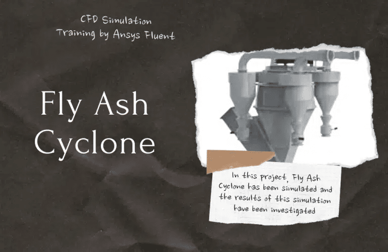
Cyclone separators are a type of particle control system utilized in industrial settings to control particulate matter emissions into the atmosphere. Cyclones use resources effectively, don’t break the bank, and use little power. The cyclone separator can separate particles of varying sizes from gas through centrifugal force. Cyclones have a high separation efficiency, which more than makes up for their design is quite complicated. Cyclones are a type of centrifugal separator comprised of a barrel, which serves as the upper chamber and is the location of the separation process, and a cone, which serves as the lower portion and is the location of the collection process.
The interactions between gas and solid particles within the cyclone affect the flow field and the effectiveness of the cyclone separator. Because of the minimal particle loading in the cyclone, particles do not affect the flow field; however, the coupling of the particle effect in-stream is considered to be considerable. The fundamental idea behind the separation process is based on the fact that particles with greater densities have greater inertia, and as a result, they have a greater tendency to revolve in a bigger radius. The denser particles rotate closer to the wall, where they are more likely to slide down, while the lighter particles rotate closer to the center and are more likely to be collected at the top of the cyclone.
After this simulation, an investigation of the movement of the particle within the cyclone was carried out. Counters for particle velocity and pressure, as well as air and gas flow, were investigated. Additionally, it was discovered that lighter and heavier particles split due to gravity and centrifugal force. It has been observed that most particles that enter the cyclone through the inlet exit through the lower outlet. Air also exits the cyclone through the higher outlet, and only a tiny number of particles are retained in the upper portion of the cyclone.
In general, CFD simulations have the potential to provide valuable insights into the behavior of particle-laden flows in DPM engineering industries. These insights, which can be used to optimize the Design and operation of industrial processes, reduce energy consumption, and improve product quality, can be utilized to optimize the Design and operation of industrial processes.
MR CFD services in the DPM Engineering Industries
With several years of experience simulating various problems in various CFD fields using ANSYS Fluent software, the MR-CFD team is ready to offer extensive modeling, meshing, and simulation services. CFD Simulation Services for DPM is categorized as follows:
- CFD simulation particle separator from gas using cyclone
- Using particle droplet combustion in two and four-stroke internal combustion engine
- Simulation particle settling by the gravity body force
- Wood combustion using the discrete phase model
- Sand particle tracking in the pond riverside
- Particle tracking in the spray dryer using the DPM model
- Simulation of using magneto-hydrodynamic (MHD) body force for increasing the performance of cyclone
- Erosion modeling in knee
- …
Spray CFD Simulation Training Package
The Spray CFD Simulation Training Package includes ten distinct CFD simulation projects carried out with the assistance of the ANSYS Fluent software and are all associated with different Sprays. MR-CFD advises anyone interested in Spray CFD analysis to consider purchasing this package. Using this program, you will become familiar with various project descriptions and designs and the process of simulating those projects while considering the results of various connected studies. This bundle contains simulated product versions created with the discrete phase model (DPM). The Lagrangian method is utilized for analysis in fluid mechanics while using the discrete phase model. In this approach, we will monitor a fluid on a particle-by-particle basis.
The discrete phase model is utilized in a variety of commercial settings. The spray technique is one of the primary applications that use this method. The investigation of spray in a variety of computer models is something that engineers and designers find interesting. This package kicks off with a standard spray product as the first item. The first product addresses the issue of spray modeling inside a constrained area.
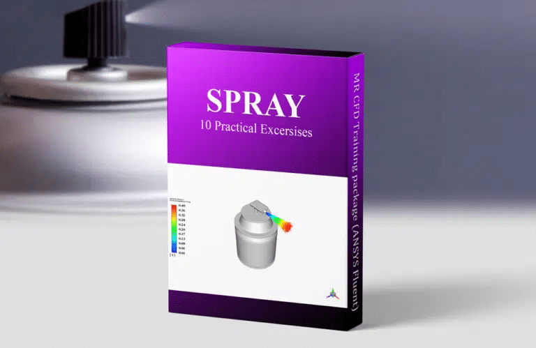
The boundary conditions of the walls subjected to color dispersion determine whether or not one of these items is superior to the other. The trap boundary condition and the wall film boundary condition are utilized in Project 4, but the trap boundary condition is utilized in Project 5. The model for product number 6 represents an air freshener. This apparatus disperses scented droplets around the room. The utilization of air fresheners is the seventh product on the list. This study aimed to investigate the influence that heaters and air fresheners had on the functioning of a restroom.
Simulation of spraying medication particles into an asthma inhalation device is the subject of the eighth product in this line. We gave complementary modeling of asthma devices used in medical applications in our product number 9, which may be found here. As part of our investigation, we looked into how asthma can spread through the human lungs via the various branches and forks that they contain.
Additionally, spraying is utilized rather frequently within combustion chambers. Fuel is pumped into the chamber to get a reaction going with the oxidizer. The simulation of fuel injection inside a combustion chamber has been the primary focus of work on Product Number 10. After completing this incredible hands-on training package, you can confidently say that you are an expert in modeling and analyzing each CFD simulation linked to sprays and their applications. Prepare yourself to work as a CFD engineer in the sectors that are relevant to this one.
DPM Engineering MR CFD Projects
Humidification / Dehumidification
Humidification Dehumidification (HDH)
This Computational Fluid Dynamics (CFD) project uses the ANSYS Fluent software to study a humidification dehumidification (HDH) system. The HDH system is a model for other methods of desalinating water. The humidification and dehumidification processes provide the foundation for this method’s underlying mechanism. The evaporator, also known as the humidifier, is located on one side of the system, while the condenser, also known as the dehumidifier, is on the opposite side.
The condenser, also known as a dehumidifier, has spiral tubes into which the cold water flows. After then, it absorbs the heat from the steam within the shell. The transfer of heat will continue until the steam cools down enough to condense; as a result, the water that is contained within the tube will get warmer. This heated water is then sprayed onto the filter plates of the evaporator, which are located inside the humidifier (also known as an evaporator).
These droplets combine with the dry air expelled from the condenser to create wet steam, also known as humidified air. The final product, the steam, is free of impurities since they are left behind in the evaporator. After being warmed up by a heater, the pure steam passes through the condenser.
As was indicated earlier, the interior of the condenser shell is now in contact with the pipes that carry the cold feed water. It may proceed via the humidification or distillation processes, separating pure water from steam. This system has a two-part mechanism, which may be broken down into the categories of humidification and dehumidification. As a result, two different simulations have been carried out for this issue. The first simulation looked at how humidification affected things.
The chamber is filled with dry air that rises from the bottom to the top. While this happens, little droplets of hot salt water are sprayed through several openings within the chamber. After being subjected to collisions with the airflow, the droplets within the chamber’s membrane portion ultimately produce humid air.
This steam is clean and contains no salt in any form. The process of dehumidification was analyzed in the second simulation. The chamber now receives the flow of moist air made in the phase before this one. The cooling water circulation is thought to be carried out inside the chamber by spiral tubes. Condensation and the creation of freshwater are the results of heated steam coming into touch with the cool surface of the spiral tube.
EHD
Electric Field Effect on Nanofluid Considering Charge Density
A nanofluid is a fluid that contains nanoparticles, which are particles that are on the nanometer scale. Because of their unique features, nanofluids have the potential to be helpful in a wide variety of applications involving heat transmission. They have increased thermal conductivity and convective heat transfer coefficient compared to the base fluid.

In this example, a cross-section of the pipes that make up the Cooling System is modeled using a curved pipe in the shape of an N. A thin wire has been inserted along the center of this pipe to apply an electromagnetic charge. At the pipe’s inlet, fresh water is allowed to flow in. The pipe body’s interior has portions with walls heated to a temperature of 390 Kelvin.
The cold water transfers heat to the walls, while the temperature rise measured at the output is kept an eye on. To improve the heat transfer coefficient of the coolant liquid, aluminum nanoparticles with a charge density of 23 were utilized, and the behavior of these nanoparticles in the presence of an electromagnetic field was explored. Ultimately, the data obtained from the modes with and without particles was compared.
DPM to VOF
A painting tool known as a spray gun is a device that atomizes a liquid into a predetermined pattern by directing compressed air via a nozzle. The operation of the spray nozzle is accomplished by impinging high-velocity, turbulent air on the surface of liquid filaments or films, which causes the filaments or films to break apart into droplets of a wide variety of sizes.
Paint can be applied on any surface using spray guns. When liquid droplets exit the nozzle at a high velocity, they can settle over the surface and create a liquid layer, ultimately becoming the paint layer. Applying paint to a wall of arbitrary shape and size is modeled and recreated in this Project. A process like this can be modeled using a variety of different modules; these modules include the VOF multiphase model as well as the DPM.
When the discrete phase model (DPM) and the VOF multiphase model (VOF) are enabled simultaneously, the user can access two transition mechanisms: DPM-to-VOF and VOF-to-DPM. These mechanisms allow users to switch between discrete phase elements and the Eulerian VOF model.
Modeling the transformation of liquid droplets into a paint layer over a wall boundary is the purpose of this research, which uses the DPM-to-VOF model. At a speed of two meters per second, the particles are ejected from the nozzle of the spray cannon in the shape of a cone.
In addition, the liquid wall film boundary condition is enabled over the painted wall so the particles can become immobilized on the painted wall in the first place. After some time, when the volume fraction of liquid droplets is high enough to produce the paint layer, the discrete particles are converted into the VOF layer, generating the final paint layer on the wall. This occurs when the volume fraction of liquid droplets is high enough.
In addition, the automated mesh adaptation is a required feature that must be activated before the game can be played. At the stage where the trajectories of the particles are being estimated, it should go without saying that small mesh cells are not required.
After the particles have been transformed into VOF, the mesh cells must be made as fine as possible to capture the paint layer’s interaction with the matter around it (the air). If this is not the case, the simulation outcomes will be prone to error and inaccuracy.
The findings indicate that a layer of paint has been deposited onto the wall. Particles that accumulated on the painted wall were transformed into a VOF layer, which resulted in the formation of distinct layers of paint. The flow pattern created inside the domain due to the particle injection jet causes the newly produced VOF layers on the painted wall to shift radially away from the wall’s center point. This is because the flow pattern was caused by the particle injection jet. Because of this motion, the automatic mesh adaptation is triggered. The final mesh image shows that the mesh cells in some specified regions are noticeably smaller than those in other locations.
Additionally, some wall film particles are still present on the painted wall even at the last time phase of the process. To prevent the simultaneous existence of wall film particles and the VOF layer, the value of the lagrangian wall film particles located beneath the dpm-to-of-session box must be changed. This will allow removing any existing wall film particles when they come into contact with the VOF layer. Additionally, seeing the velocity vectors inside the computational domain makes it intriguing to study the flow pattern formed by the injection jet flow. This is because the computational domain created the flow pattern.
Dryers (Particle Drying)
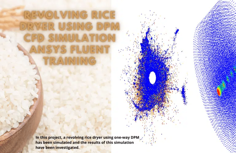
During this research, a revolving rice dryer device was modeled in Ansys Fluent employing Evaporating droplets using a one-way DPM model. The results of this simulation were then analyzed. The rice dryer gets its hot air supply from the centrally positioned porous tube with holes punched. The chamber itself is large. Approximately three million rice particles and 15 percent droplets of moisture are injected into a chamber that rotates at an angular speed of 100 rpm.
A spray dryer chamber is modeled and recreated here for your viewing pleasure. The water droplets eventually evaporate due to the water droplets arriving as particles and the heat transfer. This results in the water droplets’ diameter being smaller, which is an indication of the performance of the Spray Drying device.
The ANSYS Fluent software simulates a spray dryer in this product. First, the feed solution (a slurry, paste, or something else entirely) is pumped from a tank into the atomizer. Inside the primary drying compartment, the liquid solution is distributed by the atomizer as a spray or droplets of liquid.
On the other hand, a fan will blow hot air into the chamber. This hot air will have originated from a burner or a steam heater. At this stage, the liquid phase of the spray comes into contact with heated air, which causes the moisture inside the droplets to evaporate in a concise amount of time. This results in the powdered dry particles and the hot air being expelled from the chamber.
We have employed continuous and discrete phase methods to solve this particular issue. In an Eulerian model of a spray drier, the hot airflow responsible for evaporating the moisture in the solution enters the chamber as a continuous phase and flows inside it.
The photographs make it quite evident what the temperature, pressure, and velocity of the particles injected into the domain were. Particles can quickly infiltrate the domain as a direct result of the function of the spray dryers. While at the same time, a rush of heated air enters from all directions. The behavior of the particles while they are in the air, as well as their penetrating ability and length of disintegration, are additional topics of discussion. The combination of these two phases, which enter the domain in both the Eulerian and the Lagrangian, results in the outlet temperature being uniformly lower than the temperature of the air that enters the domain.
This study analyzed the outcomes of a Grain Drying Device CFD Simulation performed with the Two-way Discrete Phase Model (DPM) & Species Model in the Ansys Fluent program. The drying apparatus is supplied with hot air, and then 120000 rice grains containing 10% moisture are inserted randomly for 6 seconds. After the injection has been finished, the process of evaporation will continue for another 9 seconds. In addition, the hot surfaces are in contact with the exhaust smoke produced by the engine, creating an optimal environment for the drying apparatus.
Rice often has between 20 and 30 percent moisture when harvested, enough to contaminate the grains quickly. As a result, it is essential to dry the grains after harvesting them before storing them or transporting them to the rice mill. The rice drying device is a mechanical mechanism that exposes rice grains to hot air in the surrounding environment to maximize the amount of moisture evaporated.
The rice grain count at the beginning of the particle injection into the device used for drying rice is 10000. The time required for the injection operation is six seconds. By ignoring that evaporation takes place from the first second, an assumption made to simplify the process, we may obtain the H2O mass fraction graph showing the required variable as a function of time. After the injection, the moisture (H2O) reaches its highest value, about 0.015. After that, the value takes roughly 9 seconds to decline to 0 due to evaporation.
Gasification / Biomass
The ANSYS Fluent software simulates the gasification process inside a gasifier chamber for the current issue. During the gasification process, a carbon-based substance is subjected to a series of chemical processes, ultimately producing carbon monoxide, hydrogen, and carbon dioxide. This procedure produces a renewable energy source that may be utilized in various commercial settings.
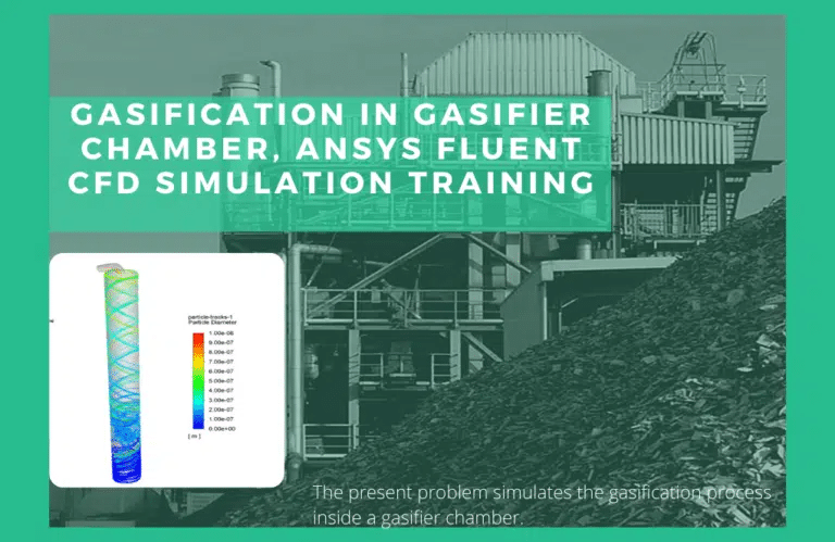
The combination of these two flows causes a reaction as soon as they enter the chamber. On either side of these input flows, two conical sections have now been utilized so that the reaction process between them can be strengthened and sped up. Additionally, each input flow enters the chamber through two pipes oriented in opposite directions to each other and at an angle of 180 degrees to each other. These factors lead to a vortex flow, which strengthens the Mixing of the two flows, and the chamber itself is positioned at an angle of 180 degrees to the two pipes.
Additionally, in this simulation, it is required to define the chemical interactions between the fluxes of input materials and the creation of the needed gaseous species. Consequently, the model of species transport with volumetric reactions has been utilized for the modeling above, and the CHEMKIN mechanism has been utilized to define the type of reactants and the process of chemical reactions. The CHEMKIN mechanism comprises five chemical reactions, each involving eight distinct types of reactants and products.
The responses that are associated with this reaction pattern are outlined in the table that can be found below. This model also assumes that heat transmission by radiation happens within the gasifier chamber due to chemical processes; hence, the P1 model is the one that is defined for simulation purposes. After finding a solution has been completed, a particle track, three-dimensional temperature and velocity counters, and three-dimensional velocity vectors are obtained. The second installment of the Radiation Model Training Course is this CFD Project you will work on.
The current issue utilizes the ANSYS Fluent software to do a simulation of the process of biomass combustion inside a gasifier chamber. This CFD project is carried out, and a CFD investigation is carried out. Biomass is the material utilized for combustion; this material reacts with the oxidizer during the process. It is a biomass substance derived from wheat straw that combines with oxygen to produce synthetic gas as a healthy fuel, and several different gas species are engaged in the reaction, either as reactants or as products.
Two distinct inlets in the upper region provide the chamber access to biomass and air fuel. In the lowest portion of the chamber, it generates a mass of materials, some of which are ash and coal that are only partially combustible. When everything is said and done, the gas produced is expelled through the outlet at the bottom of the chamber and into the subsequent stage, which is the boiler responsible for starting the combustion process.
In conclusion, we can acquire contours in two dimensions related to pressure, temperature, velocity, and density. In addition, we calculate the radiation temperature, the mass fraction of water and vapor, and the mass fraction of species. The findings demonstrate that combustion is initiated and carried out in response to the introduction of fuel particles, as hypothesized, and that the temperature of the combustion chamber rises as a result. The buildup of particles on the relatively tiny intake surface in the inlet area is the primary cause of the velocity reaching its maximum value. At the point where the nozzle opened, the temperature was the maximum. The findings also demonstrate the buildup of soot in the output area of the design.
COVID-19
Transient Breathing in the Operating Room
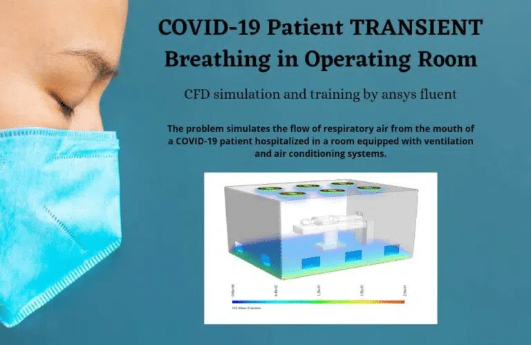
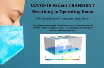
Instead of releasing contaminated air from the patient’s mouth into the surrounding environment, the primary objective of this simulation technique is to make it possible for clean air (air that contains oxygen) to flow continually into the inside of the room. The ventilation systems and air conditioners are built into the room’s ceiling and floor to circulate fresh air throughout the space and direct that air out of the room through the side pores and into the surrounding environment. When our objective is to analyze the behavior of the particles from a Lagrangian and discrete point of view, we use the discrete particle method (DPM).
In the current configuration, the patient’s mouth serves as the point of origin for the particle that carries the exhaled airflow into the interior space of the operating room. This airflow contains oxygen, nitrogen, and carbon dioxide. When the mode for tracking unsteady particles is selected, the behavior of the discrete airborne particles is altered over time. Therefore, in the presence of air conditioning and ventilation equipment in the operating room, we can quickly perform a time-efficient analysis of the CORONAvirus particle.
Wet Combustion
The wet burning of anthracite volatile in a combustion chamber is replicated with the help of combusting particles for this research. Our objective is to monitor fuel particles as they begin the process of devolatilization, oxidation, and the production of carbon dioxide and water vapor. It is important to note that the injection process takes 0.5 seconds and that the liquid component of the fuel makes up 2% of the total. During this time, hot air is being sucked into the combustion chamber. This raises the temperature of the particles, which ultimately results in the release of the volatile portion.
DPM in Industrial Companies
The behavior of scattered particles in a fluid can be modeled using a simulation approach called Discrete Phase Modeling (abbreviated DPM). Several different industrial companies utilize DPM for a variety of purposes, including the following:
– Chemical processing plants: In facilities that deal with the processing of chemicals, DPM is utilized to represent the behavior of particles in reactors, fluidized beds, and other types of chemical operations.
– Power plants: The behavior of fly ash and other particles in combustion chambers and boilers is modeled using DPM.
– Food processing plants: DPM is used in food processing plants to predict the behavior of particles in mixing tanks, spray dryers, and other equipment used in food preparation.
– Pharmaceutical manufacturing plants: In pharmaceutical production plants, DPM is utilized to mimic the behavior of particles in a variety of equipment, including mixing tanks, fluidized bed dryers, and other pieces of pharmaceutical manufacturing machinery.
– Aerospace manufacturers: DPM is utilized by aircraft equipment producers to model particles’ behavior in combustion chambers and other types of aeronautical machinery.
MR CFD has worked with clients in these industries, giving them helpful insights and advice for optimizing their systems using DPM modeling methods.
MR CFD Industrial Experience in the DPM Field
Following are some examples of a DPM industrial project recently simulated and analyzed by MR CFD in cooperation with related companies.
ICU Ventilation Design Improvement
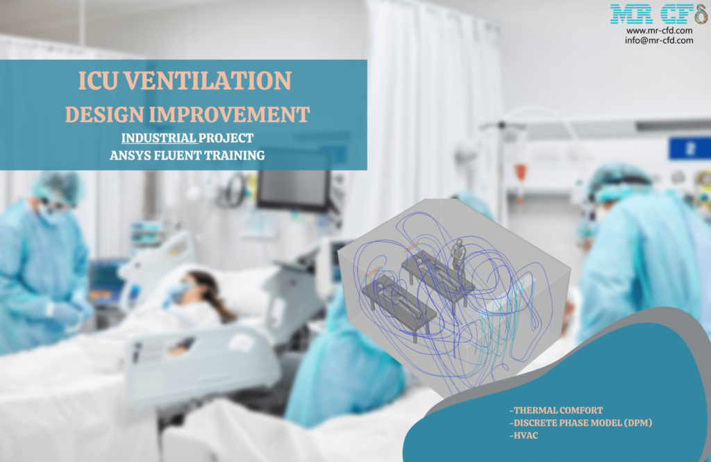
The vast majority of infectious respiratory diseases are passed from person to person, which implies that anyone in an environment with multiple people, such as a school, workplace, neighborhood, etc., has the potential to become infected with one. In the intensive care unit (ICU), the presence of breathing problems is a circumstance that is highly critical and may result in severe bodily damage. Because of this, we are looking for a clever design that will stop any transmission while giving the optimal conditions for HVAC (thermal comfort).
This Project aims to design an intensive care unit (ICU) that considers thermal comfort factors such as PMV and PPD. In addition to this, it is critical to take measures to stop the spread of infectious diseases. Within the research scope, a patient suffers from a respiratory condition, drawing additional attention to the possibility of an infection.
In addition to cement kilns, scrubbers find widespread use in the chemical and pharmaceutical industries, industrial boilers, gold plants, metallurgical industries, and incinerators. As a result, this simulation’s primary objective is to recreate a sample scrubber’s operating parameters. With these parameters, we can mimic all possible kinds of scrubbers in various sizes.
The sector has a substantial hurdle in the form of difficulty in separating particles from the gas flow. A Venturi scrubber, which filters out gas particles, is one of the most valuable instruments for finding a solution to this problem. In addition to this, it is more effective than other scrubbers (such as the wet scrubber, the cyclone scrubber, etc.).
Venturi scrubbers were developed to remove and collect particles more than 99% efficiently. Because ventures have such a high capability in situations where both the volume of incoming gas and the temperature of that gas are high, they have become popular in various sectors. They are consequently employed to remove various particles in various industries.
This feature is essential for lowering emissions from cement kilns and controlling emissions from simple oxygen kilns in the steel sector. Both of these types of kilns have an incoming gas temperature that is higher than 350 degrees Celsius. In addition, ventures are utilized to control emissions of fly ash produced by incinerators and cement and sulfur dioxide furnaces found in industrial facilities and boilers.
It is feasible to cleanse highly polluted gases with high efficiency, minimal maintenance, and unlimited capability to reverse flow thanks to the purification system’s open structure, liquid atomization, and high liquid-to-gas ratio. Venturi is one of the most adaptable systems because of its capacity to eliminate harmful gases and particles in various environments concurrently. This makes it one of the most widely utilized systems.
Scrubbers like this one are utilized in various sectors because Venturi is typically utilized in the initial step of multistage systems to manage gas or air flow pollution. An industrial Venturi scrubber was simulated using the ANSYS Fluent program for this study. Particles and gas pollutants up to 0.1 micrometers in size can be collected using venturi scrubbers. The device contains a significant volume of water. However, this increases interactions between the water and various particles and pollutants.
As a consequence of this, the scrubber can collect the particles and remove them from the fluid. It was determined, through simulation of the existing Venturi Scrubber, that this device possesses the efficiency level necessary for use in industrial settings. To atomize the gas flow scrubber, the Venturi scrubber takes advantage of the energy the inlet gas provides.
The convergent, the throat, and the divergent comprise the three components of the Venturi scrubber. The gas stream that is coming in is the one that goes into the part that is converging, and the flow rate of the gas increases as the area decreases. The liquid being used is added to the system at the point where it converges, also known as the throat or inlet. The gas entering the system travels through the throat at a high velocity. This is the location where the liquid is introduced, which results in the production of many droplets.
The throat is where the process of filtering out impurities and particles from the gas stream occurs. It is accomplished by subjecting the incoming gas stream to collisions with tiny liquid droplets. After then, the gas from the inlet goes toward the diverging section. It is the point at which the flow will escape at a low speed and become submerged in water. The simulation shows that the Venturi pressure falls, increasing velocity and turbulence. Additionally, water and particle disturbances are performed better, indicating that the device is simulated accurately.
Within the scope of this study, a Venturi 720 series scrubber of size 720-2 was modeled and simulated. However, if we wanted to utilize the Venturi scrubber in other industries (with a different type of gas flow or particle flow), we would need to adapt it. Because these simulation settings are so large, the optimal state for the chosen industry can be reached in a shorter time.
You may find the Learning Products in the Combustion CFD simulation category in Training Shop. You can also benefit from DPM Training Packages appropriate for Beginner, Intermediate, Advanced, and Expert users of ANSYS Fluent. Also, MR CFD is presenting the most comprehensive DPM Training Course for all ANSYS Fluent users from Beginner to Experts.
Our services are not limited to the mentioned subjects. The MR CFD is ready to undertake different and challenging projects in the Combustion modeling field ordered by our customers. We even carry out CFD simulations for any abstract or concept Design you have to turn them into reality and even help you reach the best strategy for what you may have imagined. You can benefit from MR CFD expert Consultation for free and then Outsource your Industrial and Academic CFD project to be simulated and trained.
By outsourcing your Project to MR CFD as a CFD simulation consultant, you will not only receive the related Project’s resource files (Geometry, Mesh, Case & Data, …), but also you will be provided with an extensive tutorial video demonstrating how you can create the geometry, mesh, and define the needed settings (pre-processing, processing, and post-processing) in the ANSYS Fluent software. Additionally, post-technical support is available to clarify issues and ambiguities.
