Comprehensive CFD Fire Simulation for Subway Stations: Optimizing Smoke Control & Passenger Safety
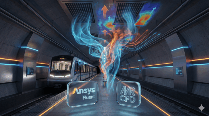
In the high-stakes world of underground transit infrastructure, there is no margin for error. A fire in a subway station is one of the most complex, hazardous scenarios a civil safety engineer will ever face. The confined geometry, combined with the “piston effect” of moving trains and high-density passenger loads, creates a volatile environment where smoke—not heat—is often the primary killer.
Traditional 1D empirical calculations (like those found in SES) are often insufficient for modern, architecturally complex stations. They simply cannot capture the three-dimensional turbulence and stratification of smoke in a multi-level atrium or a curved tunnel. This is where high-fidelity cfd fire simulation becomes not just a luxury, but a necessity for compliance and life safety.
At MR CFD, we have spent decades bridging the gap between theoretical fluid dynamics and practical safety engineering. This guide details how we approach subway station ventilation design using Ansys Fluent, ensuring NFPA 130 compliance modeling while optimizing capital expenditure.
Why is CFD Fire Simulation Critical for Underground Transit Infrastructure?
For decades, engineers relied on handbook calculations to size ventilation fans. While useful for preliminary sizing, these methods assume idealized, steady-state flow. They fail to account for the chaotic reality of a tunnel fire.
CFD fire simulation is critical because it captures the transient nature of smoke propagation. In a subway environment, airflow is not static. Trains entering and leaving stations act as massive pistons, pushing air columns that can either aid smoke extraction or disastrously overcome jet fans, pushing toxic smoke back over evacuating passengers (a phenomenon known as backlayering).
Furthermore, regulatory bodies are increasingly demanding performance-based design (PBD) over prescriptive codes. To demonstrate that a smoke control system analysis meets the tenability criteria of standards like NFPA 130 or EN 50126, you must prove—through validated simulation—that the Available Safe Egress Time (ASET) exceeds the Required Safe Egress Time (RSET). Only 3D CFD provides the spatial resolution required to visualize dead zones, recirculation areas, and the precise height of the smoke layer.
What Are the Unique Physics Challenges in Modeling Subway Fires?

Modeling a fire underground is vastly different from modeling one in an open environment. The physics involve a tight coupling of high-momentum jet flows (from ventilation fans), buoyancy-driven thermal plumes, and radiative heat transfer.
The primary challenge is the “battle” between momentum and buoyancy.
- Buoyancy: Hot smoke naturally wants to rise and stratify along the ceiling.
- Momentum: Jet fans and the piston effect introduce strong horizontal forces.
If the jet fans are too weak, the smoke backlayers upstream. If they are too strong, they can destroy the thermal stratification, mixing the smoke down into the passenger breathing zone—a counter-intuitive failure mode known as “plugholing” or turbulent mixing. Additionally, the simulation must account for species transport equations to track Carbon Monoxide (CO) and soot concentration, which directly impacts visibility.
Accurately capturing these interactions requires a solver capable of handling high thermal gradients and complex turbulence simultaneously.
How Do We Configure a High-Fidelity CFD Fire Simulation?
Setting up a simulation for life safety requires the rigour of a Solution Architect. It is not enough to simply “turn on combustion.” The setup must be physically representative and computationally efficient. Below is the workflow we utilize in our CFD Consulting Services.
How Should We Define the Heat Release Rate (HRR) and Soot Yield?
The fire source is the heart of the simulation. In Ansys Fluent, we rarely model the actual combustion chemistry (which is computationally expensive and unnecessary for smoke transport). Instead, we model a volumetric heat source and a species mass source.
Crucially, fires do not start at peak intensity. To simulate a realistic evacuation scenario, we must use a Transient fire modeling in Ansys Fluent approach, typically following a generic t2 fire growth curve defined by:
Q˙=αt2
Where:
- Q˙ is the Heat Release Rate (kW).
- α is the fire growth coefficient (kW/s$^2$), determined by the fuel load (e.g., luggage, upholstery).
- t is time (s).
We implement this using User Defined Functions (UDFs) or Profile files to ramp up the temperature and soot generation over time. This allows us to determine exactly when visibility drops below acceptable levels.
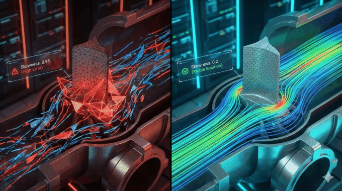
Structured vs. Unstructured Mesh: Which is Better for Smoke Propagation?

In the early days of CFD, engineers were forced to use blocky, structured Cartesian meshes (common in software like FDS). However, modern subway stations feature curved ceilings, cylindrical pillars, and complex tunnel arches. Forcing a square peg (Cartesian mesh) into a round hole (tunnel) results in “stair-step” boundaries that artificially generate turbulence and skew wall friction results.
At MR CFD, we advocate for unstructured poly-hexcore meshing. This topology provides the best of both worlds:
- Hex elements in the bulk flow for accuracy and speed.
- Polyhedral elements near complex walls to capture curvature perfectly.
We strictly enforce inflation layers (boundary layer mesh) near the ceiling. Why? Because the “ceiling jet”—the rapid spread of hot gas along the roof—governs how fast smoke detectors activate. If the mesh is too coarse near the ceiling, the simulation will under-predict the speed of smoke spread.
Which Turbulence and Radiation Models Ensure Accurate Results?
Choosing the right physics models is the difference between a pretty picture and a validated engineering result.
- Turbulence: For most smoke control applications, the Realizable k−ϵ or SST k−ω models are the industry standard. However, buoyancy corrections must be enabled in the solver settings to account for the instability caused by hot gas rising through cold air. For research-level fidelity, we may use LES (Large Eddy Simulation), though the computational cost is significantly higher.
- Radiation: Smoke obscures light, but it also radiates heat. The Discrete Ordinates (DO) radiation model is essential here. It solves the radiative transfer equation (RTE) for a finite number of discrete solid angles. This allows the simulation to account for the heat absorbed by the smoke (making it hotter and more buoyant) and the heat transferred to the tunnel walls.
What Key Performance Indicators (KPIs) Does the Simulation Reveal?
Running the simulation is only half the battle; interpreting the data for NFPA 130 compliance modeling is where the value lies. We look for specific pass/fail criteria.
How Do We Analyze Visibility and Temperature Distribution?

The primary cause of death in tunnel fires is not burning, but smoke inhalation and disorientation. Therefore, Soot visibility and toxicity tracking is our primary KPI.
Ansys Fluent calculates the mass fraction of soot (Ysoot). However, safety standards speak in terms of “Visibility Distance” (S). We use a custom field function to convert mass fraction to visibility using the extinction coefficient equation:
S=K⋅ρ⋅YsootC
Where C is a constant (typically 3 for light-reflecting signs and 8 for light-emitting signs).
We generate contour plots on breathing-zone planes (usually 1.8m to 2.0m above the floor).
- Pass: Visibility > 10m for the duration of evacuation.
- Fail: Visibility < 10m before evacuation is complete.
Is the Ventilation System Performance Sufficient for Smoke Extraction?
The second critical KPI is the prevention of backlayering. We analyze the velocity vectors along the tunnel ceiling. The ventilation system must achieve the “Critical Velocity” (Vc), defined as the minimum airflow velocity required to prevent smoke from flowing upstream against the ventilation direction.
If our post-processing reveals smoke creeping upstream of the fire source, we know the jet fan placement optimization needs adjustment, or the fan thrust is insufficient to overcome the buoyancy-driven head of the fire.
How Does MR CFD Validate Simulation Results for Industrial Clients?
In the engineering world, a simulation without validation is just an animation. Trust is built on verification. At MR CFD, we adhere to a strict Quality Assurance (QA) protocol for all safety-critical projects.
- Grid Independence Study (GCI): We never rely on a single mesh. We run the simulation on coarse, medium, and fine grids to calculate the Grid Convergence Index. This proves that the results are independent of the mesh resolution.
- Benchmark Validation: We validate our turbulence and combustion settings against standard experimental datasets, such as the ISO 9705 room corner test or the Memorial Tunnel Fire Ventilation Test Program.
- Experimental Data: Whenever possible, we calibrate our boundary conditions (like fan curves) against on-site measurements provided by the client.
This rigorous process ensures that when we present a report, it stands up to the scrutiny of external auditors and safety regulators.
Case Study: How Can Simulation Reduce Project Costs and Timelines?
We recently consulted on a major metro expansion project where the initial design called for an excessive number of jet fans to meet safety factors. The capital cost for the fans, cabling, and backup power systems was straining the budget.
By performing a detailed cfd fire simulation, we identified that the proposed fan layout was actually causing destructive interference—fans were blowing air into each other’s intake zones, reducing overall efficiency.
Through CFD Consulting Services, we optimized the layout:
- We reduced the total number of fans by 15%.
- We adjusted the pitch and angle of the remaining fans to utilize the Coanda effect (air clinging to the ceiling).
- Result: The revised design not only met the Tenability criteria with a higher safety margin but also saved the client over $250,000 in hardware and installation costs.
This demonstrates that high-end simulation is not a cost center; it is a cost-saving tool.
Ready to Ensure Safety and Compliance?
Subway safety is non-negotiable, and the complexity of modern infrastructure demands more than handbook calculations. Whether you are validating a new station design or retrofitting an old tunnel, cfd fire simulation provides the insight needed to make life-saving decisions.
At MR CFD, we offer more than just consulting. For teams looking to build this capability in-house, our Ansys Fluent Training Course covers the specific workflows for transient fire modeling, species transport, and mesh optimization.
Next Steps:
- Need a Project Solved? Book a discovery call with our technical team to discuss your ventilation challenges.
- Want to Learn? Explore our “Fire & Smoke Modeling Masterclass” to upgrade your team’s skills.
Frequently Asked Questions
What is the difference between FDS and Ansys Fluent for cfd fire simulation?
FDS (Fire Dynamics Simulator) is a fantastic, open-source tool specifically designed for fire. However, it relies on rectilinear (Cartesian) grids, which can struggle with the curved geometries of subway tunnels and complex fan blade aerodynamics. Ansys Fluent is a general-purpose solver that supports unstructured polyhedral meshing, allowing for highly accurate representation of curved walls, complex HVAC ducting, and rotomachinery, which is often critical for intricate station designs involving HVAC coupling.
How does MR CFD ensure the accuracy of smoke propagation models?
We do not rely on default settings. We utilize strict Grid Convergence Indices (GCI) to ensure our results are mathematically stable. Furthermore, we validate our turbulence (typically SST k−ω) and radiation models against standard fire benchmarks and published experimental data. This “validation against experimental data” approach ensures our predictions match physical reality, providing liability protection for our clients.
Can CFD simulation predict the exact time available for evacuation?
Yes. By performing transient fire modeling in Ansys Fluent, we simulate the fire timeline second-by-second. We can calculate the exact moment (tfail) when visibility drops below 10 meters, temperature exceeds 60°C, or CO levels become toxic at head height. Comparing this ASET (Available Safe Egress Time) against the RSET (Required Safe Egress Time) determines if the design is compliant.
What information is required to start a subway fire analysis project?
To begin a high-fidelity analysis, we typically require the station or tunnel CAD geometry (Step or Parasolid format), the fan performance curves (P-Q curves), the intended Design Fire Load (in MW, usually defined by the rolling stock manufacturer), and the specific safety standards (e.g., NFPA 130, EN 50126) the project must meet.
Does MR CFD offer training on setting up fire simulations?
Yes. We recognize that many engineering firms wish to develop in-house capabilities. We offer specialized CFD courses and Ansys Fluent training specifically tailored for safety engineers. These courses cover everything from defining the t2 fire curve via UDFs to post-processing visibility contours and analyzing critical velocity.
Related Posts
Errors Occurring in Simulations with ANSYS Fluent: A Technical Guide to Convergence & Stability
ANSYS Fluent simulates engineering problems based on the Finite Volume Method (FVM). Consequently, the errors…
How Ansys HPC Servers Accelerate Your Fluent Dynamic Simulations
We have all been there. You hit “Calculate” on a transient simulation, and the estimated…

Ansys HPC Case Study: Accelerating a 120-Million Cell Simulation Using MR CFD’s Ansys HPC Service
In the high-stakes world of aerodynamics, fidelity is everything. But as engineers, we often hit…

Comments (0)