CFD Project Outsourcing
Outsource your CFD project to the MR CFD simulation engineering team. Our experts are ready to carry out every CFD project in all related engineering fields. Our services include industrial and academic purposes, considering the ANSYS Fluent software's wide range of CFD simulations. By outsourcing your project, you can benefit from MR CFD's primary services, including CFD Consultant, CFD Training, and CFD Simulation.
The project freelancing procedure is as follows:
An official contract will be set based on your project description and details.
As we start your project, you will have access to our Portal to track its progress.
You will receive the project's resource files after you confirm the final report.
Finally, you will receive a comprehensive training video and technical support.
What is Mass Transfer?
Mass transfer is the physical phenomenon for which a net movement of generic particles is observed from one location to another. The mass transfer may occur in single-phase or over-phase boundaries in multiphase systems. Three basic types of mass transfer are distinguished:
- Diffusion in a quiescent medium
- Convective mass transfer
- The mass exchange between phases
The first is the simplest case, where the mass transfer occurs in a medium at rest. The driving force is the difference of concentrations in adjacent regions of the medium, and the mechanism is molecular diffusion. Under the statistical character of molecule motion, the substance flows from a high-concentration region to a low-concentration one tending to equalize the entire volume. However, in the second case, the mass is transferred due to the bulk motion of the base fluid. For example, the flow of liquid water transports molecules or ions dissolved in the water. Similarly, air flow transports molecules in the air, including concentrated species (e.g., oxygen and nitrogen) and dilute species (e.g., carbon dioxide). The last case, i.e., mass exchange between phases, is mainly categorized into three formats: evaporation, condensation, and Cavitation.
Mass transfer moves atoms, molecules, or ions from one phase to another. Phase concentration gradients cause it. Mass transfer can occur between solids, liquids, and gases. Diffusion, convection, and reaction can transport mass. Concentration, temperature, pressure, and chemical reactions drive these mechanisms. Chemical reactions, separation, heat transmission, and environmental processes depend on mass transfer.
Mass transfer processes:
Diffusion: Random molecular motion moves molecules or particles from high to low concentrations. Diffusion mixes things and helps gas exchange in the lungs, membrane diffusion, and solute dissolution in liquids.
Convection: Fluid flow and bulk movement. Convection improves mass transfer by moving the material. Convection-driven mass transfer includes fluid heat transfer, chemical reactor mixing, and natural convection processes.
Mass transfer by advection: Advection is the mass transfer by fluid bulk movement. Advection-driven mass transfer is ubiquitous in rivers, streams, and other fluid-flowing systems.
Mass transfer by reaction: Sometimes, mass transfer occurs during a chemical process. This can occur in gas-liquid or solid-gas reactions. Mass transfer affects reaction rate.
Distillation, Absorption, extraction, and adsorption require mass transfer. Many engineering and science sectors require understanding and optimizing mass transfer processes to achieve product quality, efficiency, and sustainability.
How can Mass Transfer CFD simulation be applied in Engineering and Industries?

Chemical process engineering: mass transfer Absorption, distillation, extraction, and reactive mass transfer are optimized using CFD models. CFD models help analyze equipment flow patterns, concentration profiles, and reaction kinetics, improving process efficiency, energy consumption, and product quality.
Environmental Engineering: CFD models help identify and mitigate mass transfer environmental concerns. CFD models may assess atmospheric pollutant dispersion, simulate gas absorption in scrubbers for air pollution control, and optimize wastewater treatment processes like aeration and activated sludge.
Heat and Mass Transfer in Energy Systems: Heat and mass transfer in energy systems are analyzed using CFD models. Combustion, heat exchangers, fuel cells, and refrigeration are examples. CFD models optimize heat and mass transfer, system efficiency, and emissions.
Food and Beverage Production: CFD models optimize mass transfer processes. This includes investigating mixing and blending, mass transfer during drying and dehydration, and fermentation and bioreactor optimization. CFD models improve quality, processing time, and uniformity.
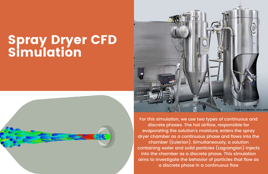
The two-way dpm & Species Transport model simulates the spray drying chamber in this CFD numerical simulation project using Ansys Fluent. 1 mm particles flow at one m/s.
Spray dryer chamber simulation. Water droplets enter as particles, and heat transfer evaporates over time, decreasing their diameter and indicating Spray Drying system performance.
ANSYS Fluent simulates a spray dryer in this product. A tank pumps the feed solution (slurry, paste, etc.) to the atomizer. The atomizer sprays the liquid solution into the main drying compartment. A fan blows hot air from a burner or steam heater into the chamber. The spray’s liquid phase hits heated air, causing the droplets’ moisture to evaporate quickly, leaving powdered dry particles and hot air out of the chamber. This problem has two continuous and discrete phases. Hot airflow, which evaporates solution moisture, continuously enters the spray dryer chamber (Eulerian).
Pictures show the domain’s velocity, pressure, temperature, and injected particles. Spray dryers accelerate particle penetration. Hot air penetrates from around. Discussed are air particle penetration and breakdown length. These two phases, which enter the domain in Eulerian and Lagrangian, leave the outflow consistently cooler than the air inlet.
Pharmaceutical/Biotech: Mass transfer Pharmaceutical and biotechnology companies use CFD simulations for medication formulation, distribution, and bioreactor design. CFD models optimize mass transfer in cell culture and fermentation bioreactors and examine drug solubility, diffusion, and release.
Separation Processes: CFD models maximize mass transfer in membrane filtration, adsorption, and chromatography. CFD models assist in explaining flow patterns, concentration profiles, and pressure drops in separation equipment, improving efficiency and energy usage.
Petrochemical and Oil & Gas Industry: Mass transfer in the petroleum industry Petrochemical and oil & gas companies use CFD simulations for gas absorption, desorption, and separation. CFD models optimize mass transport, equipment design, and process safety.
Engineers and researchers can use Mass Transfer CFD models to understand complex mass transfer phenomena, improving process design, performance, and cost in many engineering and industrial applications.
MR CFD services in the Mass Transfer Engineering and Industries
- Evaporation of water in a high-temperature pond
- Surface evaporation in desalination systems
- Dehumidification and emission removal in the surgery room
- Cylindrical perforated dryer
- Dehumidification from seeds
- Cavitation in pumps and spillways (Straight Drop, ogee, shaft, chute, Side channel, siphon labyrinth)
- …
MR CFD is a renowned CFD (Computational Fluid Dynamics) provider for Mass Transfer Engineering and Industries. MR CFD provides customized services for this industry. Services include:
CFD Modeling and Simulation: MR CFD creates precise and trustworthy CFD models for mass transfer processes. They can generate complex 3D models of equipment or systems with physics, boundary conditions, and material qualities. MR CFD uses cutting-edge software to model and evaluate mass transfer phenomena, revealing flow patterns, concentration profiles, and reaction kinetics.
Process Optimization: CFD simulations help MR CFD optimize mass transfer operations. They can evaluate existing systems, identify areas for improvement, and suggest design changes to boost efficiency, minimize energy use, and increase product quality. MR CFD’s CFD knowledge allows for design exploration and mass transfer performance measurement.
Equipment Design and Evaluation: MR CFD helps develop and evaluate mass transfer devices. They can evaluate existing equipment or suggest new designs based on client needs. MR CFD uses CFD models to optimize mass transfer efficiency, homogeneity, and safety.
Troubleshooting and Performance Enhancement: MR CFD helps clients troubleshoot mass transfer process difficulties. CFD modeling results can reveal the causes of poor mixing, mass transfer rates, and uneven concentration profiles. MR CFD then suggests improvements and fixes.
Customized Solutions: MR CFD realizes each client has distinct needs and challenges. They customize CFD solutions for mass transfer applications and sectors. MR CFD can customize models and simulations for Absorption, distillation, extraction, and other mass transfer processes.
Consulting and Collaboration: MR CFD works with clients to develop comprehensive solutions. Their engineers and CFD experts may provide direction and help throughout the Project. They collaborate with clients to implement CFD simulations for mass transfer engineering.
MR CFD’s Mass Transfer Engineering and Industries services optimize processes, improve product quality, reduce energy usage, increase safety, and save money. MR CFD helps clients in chemical process engineering, environmental engineering, energy systems, food and beverage, pharmaceuticals, and more with their CFD modeling and simulation expertise.
Productivity estimation of single-slope solar still: Theoretical and numerical analysis
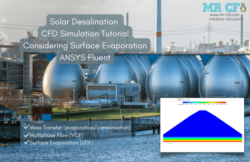
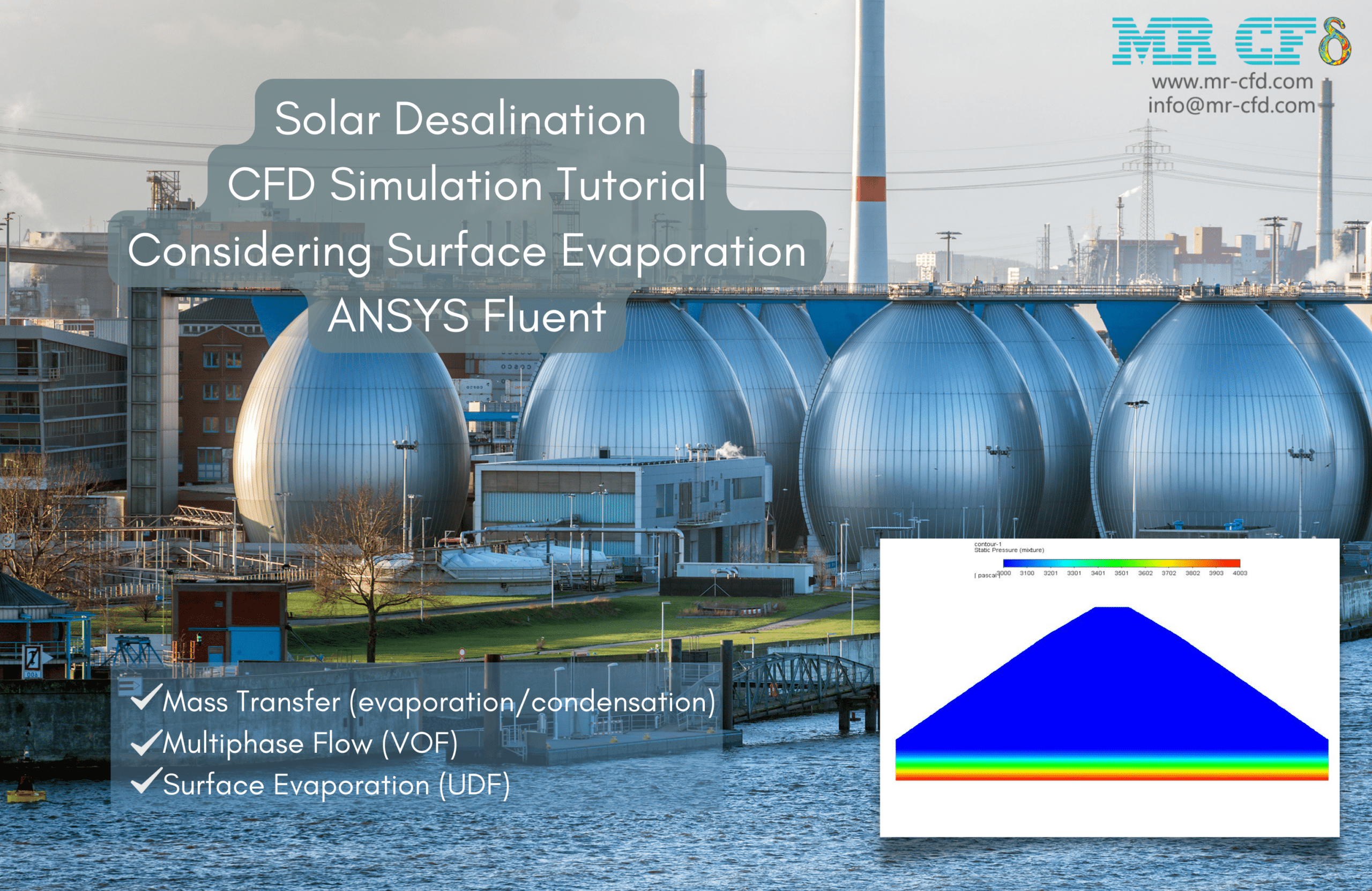
ANSYS Fluent simulates solar desalination system surface evaporation. We analyze this CFD project. This simulation compares and validates the results of a reference work [Productivity estimation of single-slope solar still: Theoretical and numerical analysis]. Evaporation happens at any liquid surface temperature. This simulation creates a single-slope solar still with a particular water height. The solar still’s glass-sloping surface transfers solar heat to the water. As sun energy passes through the glass, water evaporation rises.
Two-dimensional contours of temperature, velocity, and mass transfer rate between two phases (surface evaporation rate), air volume fraction, liquid water volume fraction, and water vapor volume fraction were obtained after the solution process. The contours show the solar still chamber water surface evaporating. Water vapor fills the chamber above the water surface.
Table 3 of the study validates this simulation. The two simulations’ surface evaporation rates are compared and validated with the paper’s model. This evaporation rate maximizes mass transfer between liquid water and water vapor. First, the glass temperature is 30 °C. In the second scenario, the glass temperature is 40 degrees Celsius, and the water temperature is 50 degrees Celsius.
Humidification Dehumidification (HDH)

These droplets mix with condenser air to create humidified air or wet steam. The evaporator collects impurities from the pure steam. Heater-reheated clean steam enters the condenser. As mentioned, the cold feed water pipelines now touch the condenser shell. Steam humidifies or distills pure water. The system humidifies and dehumidifies. This problem was simulated twice. Humidification was simulated initially.
Dry air ascends the chamber. Hot salt water is also shot through many chamber apertures. After evaporation, the membrane droplets create humid air. Saltless steam. The second simulation examined dehumidification. Moisture from the previous stage enters the chamber. Spiral tubes cool the chamber. The spiral tube’s chilly surface condenses hot steam, producing freshwater.
After the first simulation, air and water vapor mass fraction and discrete particle concentration contours were obtained. Unsteady simulations only yield findings during the last second. Two animations help explain this problem’s results. One maps variations in the mass fraction of generated h2O on a two-dimensional plane. A plane passes through the chamber. Particle Tracking examines water droplet spraying across time.
Over time, the chamber’s top openings shower droplets downward to meet the dry air. The results show that h2O gradually produces and flows toward the chamber’s higher exit. The simulation is correct because the problem was to make humid air. The mass fraction of h2o created over time was plotted. This figure shows that steam production increases over time.
Two-dimensional contours of velocity, temperature, mass transfer rate (from steam to water), and water/steam volume proportion were obtained after the second simulation. This simulation ran continuously. Phase change around the chilly spiral tube is shown. The temperature contour reveals that the vapor temperature near the cold pipe has dropped below saturation. Thus, condensation must occur.
The mass transfer rate contour illustrates that phase transition happens at temperatures below saturation. The phase transition from vapor to liquid is negative (from water to vapor is positive). The shape of water and vapor volume fraction changes confirms condensation. Results show that cold pipes yield the most water.
Solar Still Desalination CFD Training Package
This training bundle comprises 5 ANSYS Fluent Solar Still Desalination CFD simulation projects. Renewable Energy Engineering, specifically Solar Energy analysis for Clean Water, is recommended by MR-CFD. This package offers project descriptions, designs, and numerical simulations.
The training package begins with a paper validation on a Single Slope Solar Still to verify our CFD methodology using Mixture Multiphase Model. VOF multiphase model double-slope solar still desalination will follow. Finally, we use the Species Transport model solar ray tracing to mimic step solar still.
Most solar still analysis simulations require a UDF to impose Surface Evaporation as the mass transfer process. This tremendous and practical training bundle will make you a professional in modeling and evaluating CFD simulations for all solar still desalination and its applications. CFD engineers can then enter adjacent sectors.
Population Balance Model for Nucleation
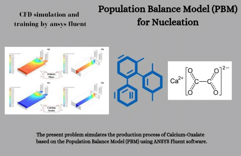
The definition category (bin) sizes table follows. Particle size classification has 48 bins, starting at 5e-7m at bin-47 and ending at bin-0. The number density bar graph also uses bin numbers. Number density indicates how many particles with the desired volume (according to bin size) are in the desired area.
Finally, we get two-dimensional contours of calcium-oxalate volume fractions by bin. From bin-30 onward, material production increases. Thus, bin-0 to bin-30 particles are negligible. Thus, the generated particles form and expand in smaller volumetric sizes (bin-47 to bin-30) and are not visible in more significant volumes.
Revolving Rice Dryer Using DPM
This Project modeled a revolving rice drier unit employing Evaporating droplets with a one-way DPM model in Ansys Fluent software. A porous tube at the center of the massive chamber lets hot air into the rice dryer. Three million rice particles with 15% moisture droplets are put into a 100rpm chamber.
Three million rice particles enter the entrance and congregate around the porous tube in the chamber. The H2o mass fraction is concentrated around the tube at first. However, the evaporating process begins due to the release of hot air from tube holes to the chamber and causes vaporizing material (H2o) to disperse. This may reduce the moisture of rice particles, which was 15% at the start, and decrease the diameter. Hot air circulation is also accelerated by chamber rotation.
How to Model Mass Transfer inside ANSYS Fluent
The ANSYS Fluent multiphase mass transfer model accommodates mass transfer between species in different phases. Instead of a matrix-type input, multiple mass transfer mechanisms must be input. Each mass transfer mechanism defines the phenomenon from one entity to another. An entity is a particular species in a phase or the bulk phase itself if it does not have a mixture of materials. The inbuilt unidirectional “constant-rate” mass transfer or user-defined functions could specify the mass transfer phenomenon. ANSYS FLUENT loops through all the mass transfer mechanisms to compute each species’ net mass source/sink in each phase. A species’ net mass source/sink calculates species and mass source terms. ANSYS FLUENT will automatically add the source contribution to all relevant momentum and energy equations, assuming that the momentum and energy are carried along with the transferred mass. For other equations, the transport due to mass transfer needs to be explicitly modeled by the user.
As discussed in the previous paragraph, mass transfer effects in the framework of ANSYS FLUENT’s general multiphase models (i.e., Eulerian multiphase, mixture multiphase, or VOF multiphase) can be modeled in one of three ways:
- Unidirectional constant rate mass transfer (not available for VOF calculations)
- UDF-prescribed mass transfer
- mass transfer through Cavitation
- mass transfer through evaporation-condensation
Steps to model mass transfer in ANSYS Fluent:
Geometry and Mesh Preparation: Create or import the geometry of the mass transfer system or equipment. Clean and mesh geometry. Create a system-specific mesh. Refine the mesh to capture length scales and flow characteristics.
Define Material Properties: Diffusivity, solubility, and density are mass transfer-relevant material qualities. Accurate mass transfer simulation requires these features.
Set Up Fluid Flow: Set up fluid flow, including inlet and output boundaries, velocities, and pressures. Turbulence modeling may be needed to represent mass transfer effects.
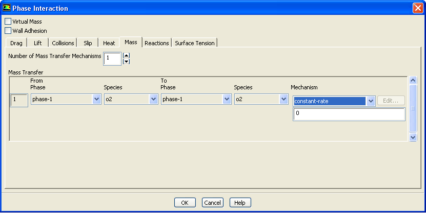
Select Mass Transfer Model: Choose a mass transfer model depending on the physical processes you want to emulate. Fluent offers diffusion-based, convection-diffusion, and more complicated mass transport models. Choose the model that best describes your system.
Solver Settings: Set convergence criterion, time step size, and numerical schemes. To get accurate results, adjust the settings correctly.
Run the Simulation: Let Fluent solve the fluid flow and mass transfer equations. Adjust the solver settings as the solution converges. The simulation may take time, depending on the problem’s complexity.
Post-Processing: Analyze and evaluate the simulation results. Fluent offers post-processing capabilities to view and extract concentration profiles, mass transfer rates, and flow patterns. Use these tools to understand mass transfer in your system.
The stages and options depend on your mass transfer problem and ANSYS Fluent version. For detailed instructions on modeling mass transfer in ANSYS Fluent, consult your version’s documentation and tutorials.
Evaporation
Evaporation is a simultaneous heat and mass transfer process. This phenomenon occurs at a saturated liquid surface, where the vapor diffuses into the unsaturated gas. During evaporation, the gas directly above the surface of the liquid is saturated with moisture via molecular diffusion; in the absence of gas movement, it spreads further into the bulk gas by diffusion.
Evaporation CFD Simulation Training Package
The ANSYS Fluent Evaporation CFD Simulation Training Package teaches how to model ten evaporation designs using the software. Projects included:
- Spraying Considering Breakup and Evaporation
The DPM and Species Transport model will simulate water spraying from a nozzle, including droplet breakage and evaporation.
ANSYS Fluent simulates solar desalination surface evaporation. We analyze this CFD project. This simulation creates an angled glass plate solar still. Solar rays reach the system’s water surface through the glass—heating water surface evaporation. Pure steam is produced, and impure elements settle at the bottom. Pure steam strikes the inclined glass’s inner surface and cools, causing condensation. The slope of the glasses directs distilled water drips to the outflow.
After the solution, water, air, and vapor phase temperature, pressure, and volume fraction contours were obtained. The data confirm that water evaporates off the surface over time. Thus, the water level drops. The results also suggest that phase change may not occur at saturation temperature. Thus, the UDF-based phase change technique functioned correctly.
- Falling Water Droplet Surface Evaporation
ANSYS Fluent simulates the surface evaporation of a falling water droplet. We analyze this CFD project.
- Two-stage Water Desalination
This Project simulated Surface Evaporation inside the Desalination System using the multiphase VOF model and examined the results.
- Dehumidifier, VOF Model
This ANSYS Fluent simulation of a dehumidifier using the VOF model was analyzed.
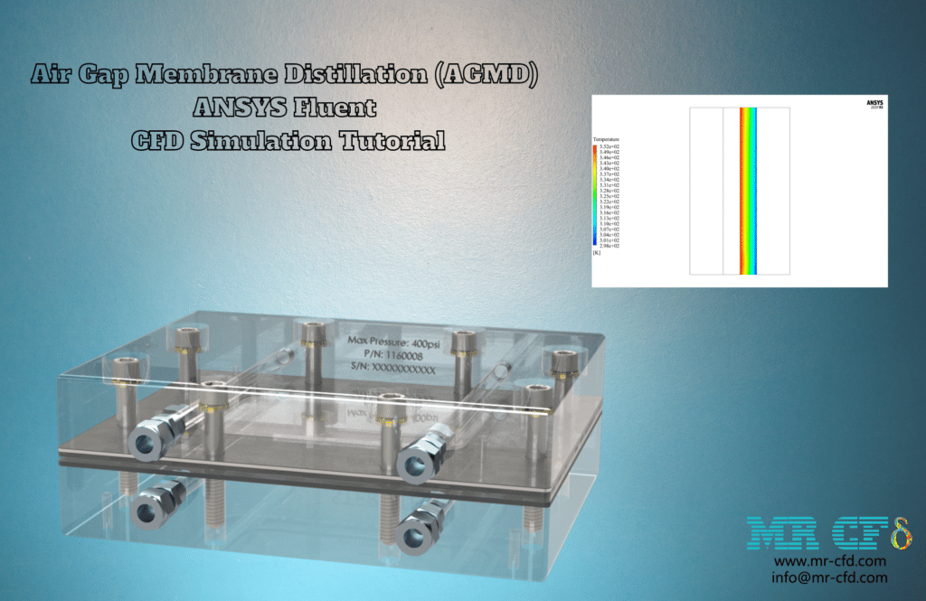
ANSYS Fluent simulates air gap membrane distillation (AGMD). Thermal and membrane desalination technologies are available. Heat and phase change is needed to make fresh water thermally. Membrane methods require particular membranes to filter water. Combining various desalination technologies is possible. This category includes MD desalination systems.
It combines membrane and thermal techniques. Filters catch impurities due to a phase change. This system has two pathways. The heater heats cold feed water on one side. Hot brine water flows from the other side of the system. Condensation occurs between these sides.
A specific membrane and condensing plate (which converts steam to water) are installed between the condensing zone and the hot and cold sides of the system, respectively. This method uses condensation to desalinate water, but the membrane purifies it beforehand. If heated water vapor flows through the barrier and condenses, four possibilities exist:
- Condenses directly in a cold stream: DCMD (Direct Contact Membrane Distillation)
- It condenses in a cold-stream-cooled air gap: (Air Gap Membrane Distillation)
- The vacuum pump sucks it, condenses it in an isolated condenser outside the system, and separates: (Vacuum Membrane Distillation)
- It then sweeps and condenses gas flow in an independent condenser outside the system, separating the net flow: (Sweeping Gas Membrane Distillation)
This issue examined AGMD desalination system performance. Simple four-part system. Cold water enters from the right. Hot feed water arrives from the left. The membrane and air gap are next to the feed water and cold sides. Assume the hot supply water has been turned to steam for simplicity. Saturated steam enters this segment to condense in the air gap. The contours for temperature, phase change rate, and water/vapor volume fraction were derived after the simulation solution.
The air gap’s cold side cools. Temperature contours represent the thermal boundary layer. Condensation or phase change is more significant in colder climates. The vapor-to-liquid phase shift rate is negative. A layer of liquid develops on the air gap cold plate when the volume fraction contour of distilled water is examined. Gravity pulls this freshwater down the air gap. The results show that the water desalination system and membrane distillation mechanism function.
- Water Distiller (Domestic)
ANSYS Fluent simulates a household water distiller. Distillation can desalinate water.
- Sub-Oceanic Volcanism
This study studies underwater volcanic activity. Oceanography and engineering use underwater eruptions.
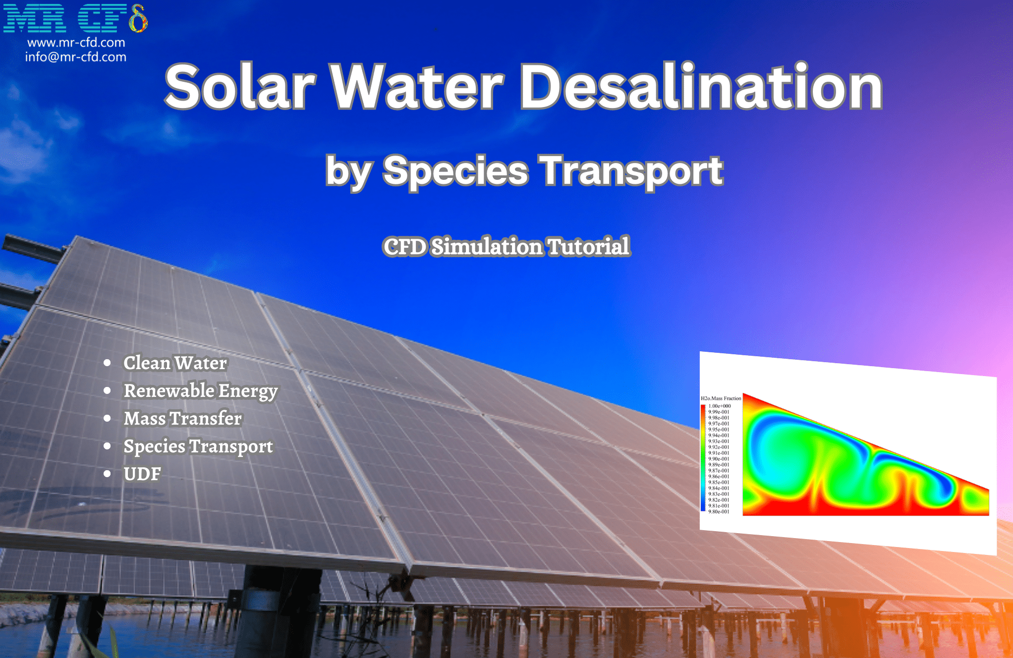
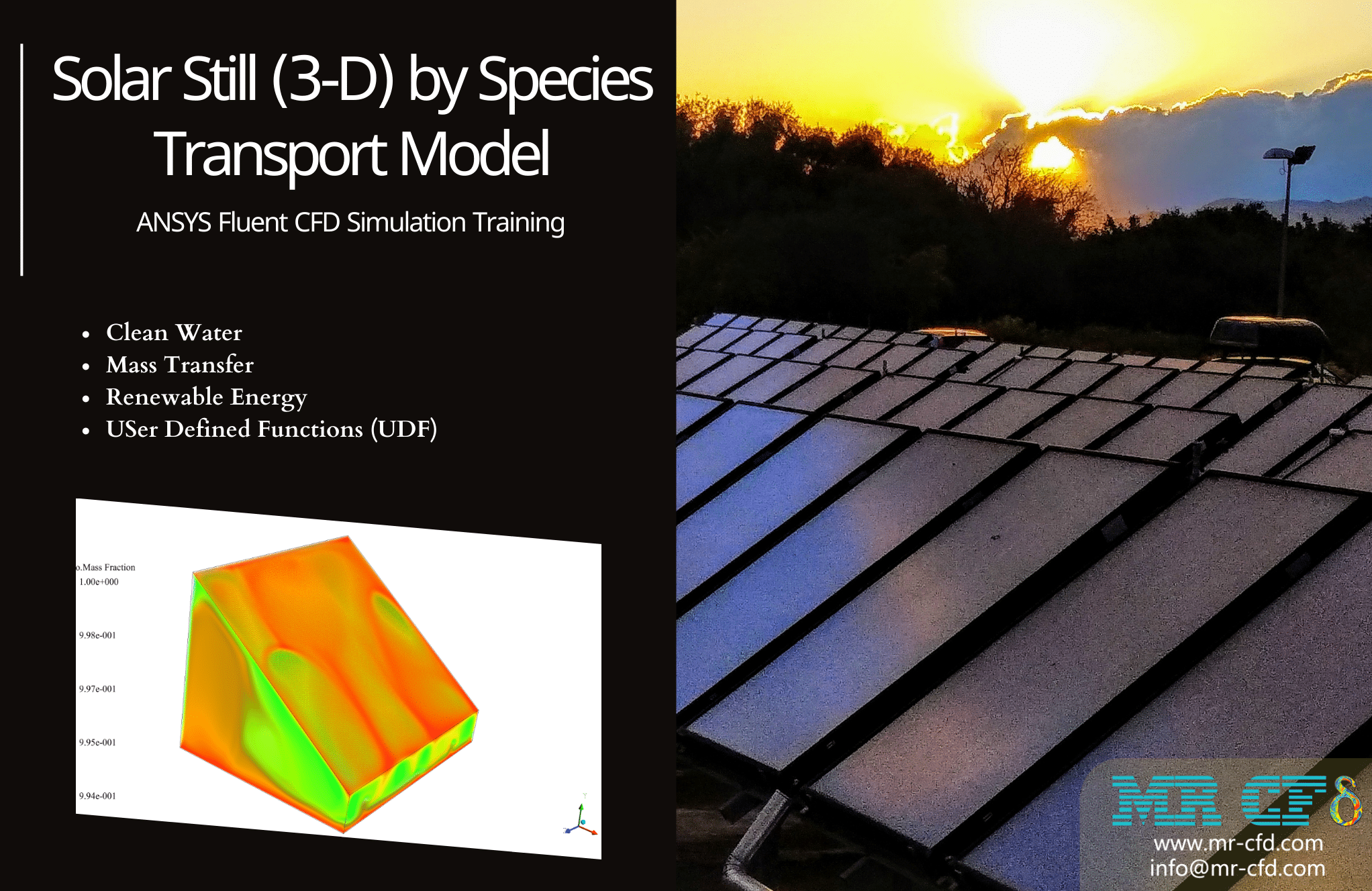
ANSYS Fluent software evaluates a solar-still thermal desalination machine. This variant has a small chamber with a tilting glass top. The enclosure’s water surface evaporates due to sun heat passing through the glass. Vapor hits the cool glass and distills. Hot vapor distillation water flows down the glass plate and releases as pure water.
Species Transport solves this. Unlike multiphase simulations, which require more processing, this method does not model saline water flow in the device. This assumes the compartment contains air and vapor. The simulation looks at the system’s vapor production, and this study examines the water and cold surfaces of the sloped plate’s vapor production.
This method does not imitate distilled water movement and assumes the chamber inside contains air and vapor. At the start of the simulation, the chamber is filled with air alone, and the bottom plane is regarded as the water’s surface. Since water evaporates on the surface, it is assumed that the surface is vapor. Steam collides with a vapor-only sloping plate.
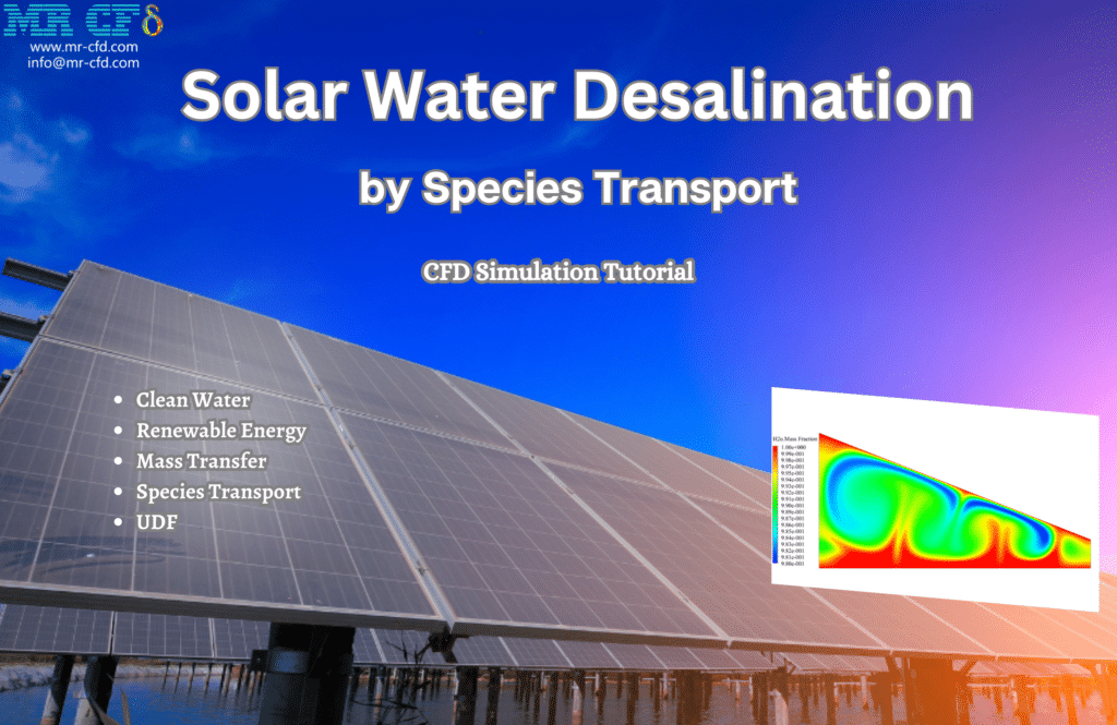
The chamber’s bottom plane is regarded as the water’s surface, and as water evaporates on the surface, it is presumed to be vapor at the start of the simulation. The sloping plate where steam collides is thought to be vapor. So water and air mass fraction contours ultimately reveal device evaporation.
Condensation
When a liquid and its vapor are in contact, molecules pass from liquid to vapor and liquid. Condensation occurs when the number of molecules entering the liquid phase exceeds that of leaving molecules. Under these circumstances, the vapor temperature in the vapor-liquid interface’s immediate vicinity (a few mean accessible paths) is higher than that of the liquid. The interface temperature drops increase with increasing condensation rate and decreasing pressure. Still, in most circumstances (an exception being the case of liquid metals), this is very small, and equilibrium conditions at the interface can be assumed.
Cavitation
Cavitation is defined as the formation of the vapor phase of a liquid when it is subjected to reduced pressure at a constant ambient temperature. Thus, it is boiling in a liquid due to pressure reduction rather than heat addition. However, both cases’ basic physical and thermodynamic processes are the same. A liquid is said to cavitate when vapor bubbles form and grow due to pressure reduction. When the phase transition results from hydrodynamic pressure changes, a two-phase flow composed of a liquid and its vapor is called a cavitating flow.
Cavitation CFD Simulation Training Package
The ANSYS Fluent Cavitation CFD Simulation Training Package teaches how to model five cavitation designs using the software. Projects included:
- Boat propeller cavitation
This Project simulates propeller blade cavitation caused by pressure drop on one side.
This Project simulated Cavitation in a cross-flow turbine without an airfoil, with an airfoil at the entry, and with an airfoil and compared its angle to the second scenario.
Turbo vehicles and blades experience Cavitation. This corrosion destroys edge surfaces. In this simulation, the pressure contour shows that Cavitation and phase change occur in the right blades due to shallow and vapor pressure at such temperatures. Thus, the right blade’s pressure drop is caused by edge suction from bottom to top.
Case 2
An airfoil prevents Cavitation in the turbine inlet. This design prevents Cavitation from forming on the airfoil.
Case 3
The preceding case prevents Cavitation by placing an airfoil at the turbine inlet and rotating it 15 degrees clockwise. This step examines how airfoil angle affects intensity. Cavitation
The contours from the volume fraction of the second phase show that Cavitation is slightly less than in the prior case. Hence the airfoil clock rotation has helped us.
- Axial Inducer Cavitation
ANSYS Fluent software simulates Cavitation flow through an axial inducer using a multiphase model because Cavitation causes a phase change between liquid and vapor.
- Radial Flow Pump Cavitation
This three-dimensional Bladegen-designed device promotes Cavitation in radial flow pumps.
- Cavitation-Aware Water Jet
This Project explains two-phase VOF flow and Cavitation in a water jet.
Each Project provides a thorough tutorial on how to set up, run, post-process, and view the simulation results. Input data, boundary conditions, and other tools are included to start cavitation modeling projects.
Boiling
Boiling involves heat and mass transport. CFD simulations can forecast bubble formation, growth, departure, and heat and mass transfer rates in boiling processes.
Boiling CFD Simulation Training Package
The ANSYS Fluent Boiling CFD Simulation Training Package shows how to model four boiling designs using the software. Projects included:

This study examines a cylindrical chamber’s saturated water pool boiling.
2. CFD Tutorial: Boiling and Bubble Formation
Changing the volume fraction discretization in this simulation showed how HRIC-compressive-Geo-reconstruct models affect output results.
3. Nanotube boiling CFD Simulation Training
ANSYS Fluent simulates nanotube boiling.
4. Pool Boiling and Surface Wettability, Paper Validation
ANSYS Fluent models nucleate boiling in a vertical channel. “A numerical investigation of the effect of surface wettability on the boiling curve” is the reference for the simulation. The article’s results validate it.
Surface Wettability Effect on Pool Boiling
ANSYS Fluent models nucleate boiling in a vertical channel. “A numerical investigation of the effect of surface wettability on the boiling curve” is the reference for the simulation. The article’s results validate it. The pool Boiling Curve Surface Wettability Effect is examined. The saturated water in the canal is 373K. The channel’s bottom heat plate (375-475K) accounts for paper-based discrepancies.
The water will boil when it hits the channel’s 100°C bottom wall. If large enough, it will boil and form a hot bubble. This simulation compares and validates the present work’s results with the article. Figure 8 shows how variations affect fluid-transmitted heat flux. The project contact angle is 60 degrees.
Mass Transfer MR CFD Projects
MR CFD has executed mass transfer projects in numerous industries. MR CFD mass transfer projects include:
Absorption Tower Optimization: MR CFD worked with a chemical processing company to optimize a gas-liquid mass transfer absorption tower. CFD simulations examined tower flow patterns, concentration profiles, and mass transfer rates. MR CFD’s design adjustments increased tower efficiency and reduced solvent usage, saving the client money.
Membrane Separation Process: MR CFD helped a water purification firm create a membrane separation technique. CFD simulations examined membrane module flow and mass transfer. MR CFD optimized membrane configuration and operating conditions to increase separation efficiency and process performance for the client.
Air Gap Membrane Distillation (AGMD)
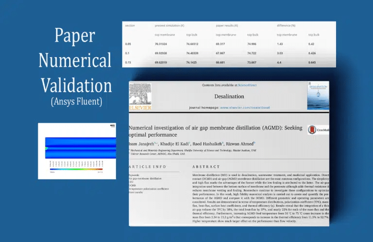
The model’s water flow has a Reynolds number of 100, so the inlet velocity of the hot salt water flow, airflow, and cold-water flow is 0.1 m/s. Saltwater flows left to right, and air and cold water flow right to left. This system transfers heat from the space associated with hot salt water flow to the membrane component of the model, which then transfers the equivalent amount of heat to the airflow space.
After the solution procedure, the present work’s outcomes were compared and validated with the reference articles. In Reynolds mode 100 and surface water temperature 75 ° C, Figure 12-c of the paper validates the results. For this, the fluid bulk temperature in the passage of salt water flow space and the upper wall of the membrane space is measured at 0.05 m, 0.10 m, and 0.15 m. The REPORT command, lines, and points in the three parts determine the temperature.
Distillation Column Design: MR CFD designed a distillation column for separating volatile compounds with a petrochemical business. CFD simulations analyzed column fluid flow, heat transfer, and mass transfer. MR CFD adjusted column geometry, packing material, and operating parameters to improve separation efficiency and reduce energy usage.
Bioreactor Performance Enhancement: MR CFD worked with a pharmaceutical company to improve a bioreactor used for fermentation. They found bioreactor mixing and mass transfer issues by modeling flow, mass transfer, and reaction kinetics. MR CFD recommended impeller configuration and baffle placement to improve mixing and mass transfer and increase product yields.
Air Pollution Control System: MR CFD designed and optimized an air pollution control system for a manufacturing company. CFD simulations analyzed pollutant mass transport and dispersion. MR CFD suggested moving scrubbers and exhaust outlets to increase pollutant capture and meet environmental laws.
These are some of MR CFD’s successful mass transfer projects. They have applied CFD simulations to mass transfer processes in chemical engineering, environmental engineering, energy systems, and more. MR CFD’s expertise in modeling and optimizing mass transfer systems help clients achieve efficient and cost-effective mass transfer operations.
Gasification in Gasifier Chamber, P1 Radiation Model
ANSYS Fluent simulates gasification in a gasifier chamber. Gasification converts carbon-based substances to carbon monoxide, hydrogen, and carbon dioxide. This technique produces renewable energy with several industrial uses.
Mass Transfer in Industrial Companies
Industrial processes across sectors depend on mass transmission. Industrial mass transfer examples:
Chemical and Petrochemical Industries: Chemical and petrochemical industries use mass transfer for distillation, Absorption, and extraction. To separate and purify goods, these techniques transport components between liquid-liquid or gas-liquid phases. These industries use distillation columns, absorption towers, and liquid-liquid extractors.
Food and beverage industry: Evaporation, drying, and extraction require mass transfer. Drying solids removes moisture, while evaporation concentrates liquids. Flavors, fragrances, and bioactive chemicals are extracted from natural sources into solvents or food matrices.
Environmental Engineering: Wastewater treatment and air pollution management require mass transfer. Adsorption, Absorption, and stripping remove contaminants from wastewater and gas streams. Activated carbon filters, scrubbers, and biofilters are employed in these applications.
Pharmaceutical Manufacturing: Crystallization, drying, and extraction require mass transfer. Drying pharmaceutical items removes solvents, whereas crystallization transfers solute from liquid to solid. Extraction techniques isolate active chemicals from natural sources or separate medication formulation components.
Energy Sector: Natural gas processing, carbon capture, and fuel cells use mass transfer. Producing pipeline-quality natural gas requires hydrocarbon separation. Carbon capture systems remove CO2 from flue gases. Mass transfer facilitates fuel-oxidant electrochemical reactions in fuel cells.
Water Treatment: Desalination, ion exchange, and membrane filtration require mass transfer. Freshwater is produced by desalinating seawater or brackish water. Membrane filtration removes pollutants via mass transfer through semi-permeable membranes, while ion exchange removes particular ions from water.
These are some industrial mass transfer instances. Mass transfer techniques help industries separate, purify, and change materials, improving product quality, environmental impact, and process efficiency.
MR CFD Industrial Experience in the Mass Transfer Field
Some examples of a Mass Transfer industrial project were recently simulated and analyzed by MR CFD in cooperation with related companies on the MR CFD website.
You may find the Learning Products in the Mass Transfer CFD simulation category in Training Shop. You can also benefit from the Mass Transfer Training Package, which is appropriate for Beginner and Advanced users of ANSYS Fluent. Also, MR CFD is presenting the most comprehensive Mass Transfer Training Course for all ANSYS Fluent users from Beginner to Experts.
Our services are not limited to the mentioned subjects. The MR CFD is ready to undertake different and challenging projects in the Combustion modeling field ordered by our customers. We even carry out CFD simulations for any abstract or concept Design you have to turn them into reality and even help you reach the best strategy for what you may have imagined. You can benefit from MR CFD expert Consultation for free and then Outsource your Industrial and Academic CFD project to be simulated and trained.
By outsourcing your Project to MR CFD as a CFD simulation consultant, you will not only receive the related Project’s resource files (Geometry, Mesh, Case & Data, …), but also you will be provided with an extensive tutorial video demonstrating how you can create the geometry, mesh, and define the needed settings (preprocessing, processing, and post-processing) in the ANSYS Fluent software. Additionally, post-technical support is available to clarify issues and ambiguities.
