Project Outsourcing
Outsource your project to the MR CFD simulation engineering team. Our experts are ready to carry out every CFD project in all related engineering fields. Our services include industrial and academic purposes, considering the ANSYS Fluent software's wide range of CFD simulations. By outsourcing your project, you can benefit from MR CFD's primary services, including Consultation, Training, and CFD Simulation. The project freelancing procedure is as follows:
An official contract will be set based on your project description and details.
As we start your project, you will have access to our Portal to track its progress.
You will receive the project's resource files after you confirm the final report.
Finally, you will receive a comprehensive training video and technical support.
What are Acoustic and Aeroacoustics?
Acoustics, sometimes called acoustical physics, is the science that deals with the production, transmission, reception, control, and effects of sound in gases, liquids, and solids. The sound may be produced when a material body vibrates; it is transmitted only when there is some material body, called the medium, that can carry the vibrations away from the producing body; it is received when a third material body, attached to some indicating device, is set into vibratory motion by that intervening medium. However, the only vibrations considered sound (or sonic vibrations) are those in which the medium vibrates in the same direction as the sound travels and for which the vibrations are very small. When the rate of vibration is below the range of human hearing, the sound is termed infrasonic; when it is above that range, it is called ultrasonic. The term supersonic refers to bodies moving at speeds greater than the speed of sound and is not typically involved in studying acoustics. There are many examples of vibrating bodies producing sounds. Some examples are as simple as a string in a violin or piano or a column of air in an organ pipe or a flute; some are as complex as the vocal cords. The sound may also be caused by a significant disturbance that causes body parts to vibrate, like sounds generated by a falling tree.
Acoustics is the science of sound and its behavior in different environments. It involves the study of the generation, propagation, and reception of sound waves and their interaction with different media, such as air, water, and solids. Acoustics has many applications, including noise control, speech and music production, and medical imaging.
Aeroacoustics is a subfield of acoustics that studies sound generated by airflow or other gases around solid objects, such as aircraft, wind turbines, and automobiles. Aeroacoustics involves the study of the complex interactions between the flow of air and solid objects, which can lead to noise generation. Aeroacoustics aims to develop techniques to reduce the noise generated by these objects, which can significantly impact human health and the environment. Aeroacoustics has applications in the aerospace, automotive, and wind energy industries.
How can CFD simulation be applied in Acoustic Engineering Industries?
The following are some of how a CFD simulation might be used in the Acoustic Engineering Industries:
– Noise Control:
Computational fluid dynamics (CFD) simulations can be utilized to make predictions regarding the amount of noise produced by a variety of sources, including but not limited to engines, fans, and pumps. The simulations can be used to either optimize the Design of the sources to lower the amount of noise they produce or develop noise barriers to lower the amount of noise that is transmitted.
 – Room Acoustics:
Acoustics of Rooms Computational fluid dynamics (CFD) simulations can predict the acoustic behavior of rooms such as recording studios, concert halls, and auditoriums. The simulations can optimize the rooms’ Design to attain the required acoustic qualities, such as reverberation duration, sound pressure level, and clarity. This can be accomplished by using the simulations.
– Sound Absorption:
Computational fluid dynamics (CFD) simulations can be utilized to develop and optimize sound-absorbing materials like acoustic foams and panels. The simulations can be used to make predictions about the materials’ absorption coefficients and improve the designs of those materials to attain the required acoustic performance.
MR CFD services in the Aeroacoustic Engineering Industries
With several years of experience simulating various problems in various CFD fields using ANSYS Fluent software, the MR-CFD team is ready to offer extensive modeling, meshing, and simulation services. Simulation Services for acoustical simulations are categorized as follows:
- Sound Generation on Airfoils
- Plate Silencer and Sound Absorption (muffler simulation)
- acoustical effects around Aerial Structures
- Acoustic Simulations of rotary machines
- …
You can obtain a comprehensive Acoustic Concept in ANSYS Fluent for free via MR CFD Training Shop. An overview of the various acoustic CFD simulation models accessible in ANSYS Fluent will be provided at the beginning of this video. You will also get a general introduction to the Acoustic Model. This section is further divided into the following subsections:
- An introduction to acoustics as well as aero-acoustics
- An introductory look at acoustic modeling simulations
- The Direct Acoustic Simulation Method: an Overview
- An Introduction to the Methods of Hybrid Acoustic Simulation
- Wave equation developed by Ffowcs, Williams, and Hawkings (FW-H)
- A brief introduction to the acoustic simulation method of Broad Band Noise
- An examination of the most critical sound wave parameters
This item is the first part of the Acoustic Model Training Course that has been released.
The following are some of how a CFD simulation might be used in the Aeroacoustic Engineering Industries:
– Noise Produced by Aircraft
Computational fluid dynamics (CFD) simulations can accurately forecast the amount of noise aircraft produces during takeoff, landing, and cruising. The simulations can improve the aircraft design by modifying the wings’ form and the engines’ positioning to lessen the noise produced.
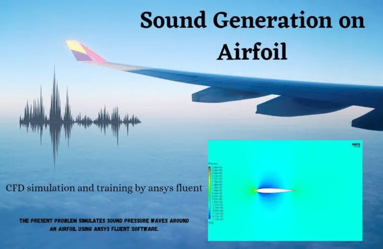
Sound Generation on an Airfoil at 3 Different Attack Angles
Using the ANSYS Fluent program, the problem models the behavior of sound pressure waves as they pass through and around an airfoil. Because the sound waves produced by aerospace devices like airfoils are at such a high frequency, discussing topics linked to sound waves is essential to the aerospace industry and its related industries. The sound waves generated around the body of an airfoil are the focus of this study. In addition, the Broadband Noise Sources model was utilized to establish the kind of acoustic model used for this particular piece of work.
– Noise Produced by Wind Turbines
Computational fluid dynamics (CFD) simulations can be used to make predictions about the noise produced by wind turbines, which can have a substantial adverse effect on both the environment and the health of humans. To lessen the amount of noise produced, the simulations can be utilized to fine-tune the Design of the wind turbines, including the blade shape and the tower’s height.
FW-H and Broadband Noise Comparison on a HAWT
In this tutorial, we will investigate the differences between two prominent models for predicting acoustics in fluids, including Ffowcs Williams-Hawkings (FW-H) and Broadband noise model, to investigate the noise and sound generation due to the rotating motion of a horizontal axis wind turbine (HAWT). This will be done to investigate the noise and sound generation caused by a horizontal axis wind turbine (HAWT).
Due to the CFD’s internal workflow for calculating pressure and viscous tensions created by the medium flowing over various solid structures, one of the most exciting applications of CFD for engineers is its capability to anticipate sound waves and sounds. This is one of the reasons it is one of the most intriguing uses of CFD. This skill has a wide variety of applications and uses.
For example, a CFD simulation can be used to estimate the amount of noise produced by enormous buildings such as wind turbines or even by the most slight disturbance in the air that the movement of a fly will cause. The Acoustic Training Course has reached its 5th installment with the release of this product.
When the FW-H model is active, the user must explicitly describe the source and receiver of sound waves. This is relevant to modeling the noise generation that wind turbines are responsible for. Although the user can define any source or receiver in the computational domain when using the FW-H model, the model’s limitation is that the user can only extract specific kinds of results, such as FFT analyses of sound waves formed in the domain. This is the model’s primary shortcoming.
In contrast to the FW-H model, in which the user was required to explicitly identify receivers, the Broadband noise model allows every point inside the domain to function as a receiver. As a result, this model has an advantage over the FW-H model in that it can extract a wide variety of graphical outputs and data, ranging from the influence of shear on the formation of acoustic waves to the sound pressure level at any given position within the domain.
You will learn how to use two of the most well-known models for predicting the generation of acoustic waves within a computational domain containing a wind turbine with a horizontal axis by following the steps outlined in this lesson. Strong sound waves will be produced as a result of the rotational motion of the HAWT as well as the airflow that passes over such a structure. These sound waves could potentially be detrimental to human hearing at close range.
As a result, to examine such a phenomenon, we used acoustic models within ANSYS Fluent. These models included FW-H and Broad band noise. Several sets of outcomes and pieces of data demonstrate the capabilities, advantages, and disadvantages that one model may have over another.
– Noise Produced by Fans
Ducted Fan: Noise and Thrust CFD Study
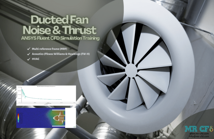
The noise level created by the fan is measured by two different sound receivers strategically placed throughout the room. The first receiver is in front of the fan (receiver 1), while the second is in front of the building, close to the door (receiver 2). The outlines show that air is moving into the domain at a speed of 0.5 meters per second, where it subsequently proceeds to depart the domain after producing a wake around the fan zone. Additionally, the duct functions as a muffle and restricts sound propagation throughout the room.
As a result, even if the sound pressure level is high in receiver 1, it is within an acceptable range close to the receiver 2, which means that the occupants won’t have any issues due to the noise. The A-weighted pressure level demonstrates that the claim is accurate and, at its highest point, shows a value of 80 dB, lower than 120 dB. After all, the value of the thrust force is stated to be 54.113455N.
– Noise Produced by Compressors
Air Compressor Acoustics Analysis
Within the context of this Project, the ANSYS Fluent software is utilized to perform a simulation of the Air Compressor Acoustics Analysis. Using the ANSYS Fluent program, the current challenge also replicates the aeroacoustics and sound generation by an airflow inside a four-row multistage compressor (axial flow compressor).
These days, makers of engines employ a wide variety of strategies to lessen the noise pollution their products create. The first thing that must be done this way is to determine how much noise each engine component generates. In this Project, we use the periodic boundary condition, and the Broadband Noise Sources model is what we turn to define the acoustic model. Because we have already looked at the matter of the turbomachinery in this particular instance, the acoustic review will proceed with the same settings as before.
According to the findings of the observations, the rotors have a more significant proportion of the components that generate sound and display an increase in acoustic Power in the corresponding contour. Contour linear The equations of Euler demonstrate the rate at which sound travels through the space gap between the rotor and the stator.
– Sound Absorption by Silencers
The ANSYS Fluent software was utilized to simulate the sound pressure waves absorbed by a plate silencer for the current situation. The vibrations in the silencer are caused by the muffler picking up sound waves from the surrounding environment, which forms the basis of the functioning mechanism of these devices. The sound wave and the mode forms of the silencer components (the plate silencer, specifically) finally converge, and as a result, the muffler can take in the surrounding sound waves and muffle them. The plate silencer contains some plates to carry out the stages above. The plates absorb the sound as a result of the vibration that is induced by the sound waves. This causes the plates to change their mode forms. These mufflers find applications in various industries, including metallurgy, Power, mining, subway tunnels, automobile, and interior architecture.
The silencers’ material and design style are such that they can absorb the noises produced with varied frequencies. Furthermore, they can give environmental comfort conditions in terms of sound within the range of human hearing from 63 to 800 Hz. Because of this, simulation and analysis of these silencers are critical. If the muffler is designed poorly, it will not only be unable to absorb sound but also worsen the current sound issues. In this Project, a plate silencer is modeled with a symmetrical structure that includes a sinusoidal or wavy plate in the middle of its body. This plate is located in the center of the plate silencer.
This simulation assumes that the appropriate pressure waves have already been formed inside this muffler. The purpose of the work that we are doing is to analyze the behavior of these waves in the longitudinal direction of this muffler as well as the efficiency of the plate silencer. The Ffowcs-Williams and Hawkings model is utilized in this simulation to define the acoustic model.
After finding a solution, we are presented with two-dimensional counters associated with pressure, velocity, and temperature, in addition to diagrams showing changes in velocity along the axis central to the system. In addition, the Sound Pressure Levels (dB) of both the input and exit receivers are presented in various frequencies. At long last, the schematic of the transmission loss is here for your perusal.
– Automotive Noise
Computational fluid dynamics (CFD) simulations can be utilized to predict the noise produced by automobiles and trucks accurately. To cut down on the amount of noise produced, the simulations can be used to improve the Design of the cars, such as how the body is shaped and where the engine is located.
Sound Generation on a Car With and Without Spoiler
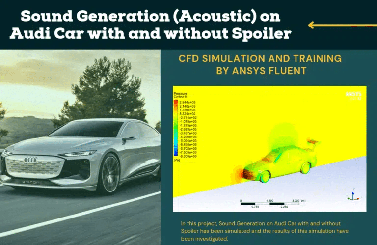
The study of mechanical waves in gases, liquids, and solids is the focus of the scientific discipline known as acoustics. Some examples of these types of waves are sound, vibration, ultrasound, and infrasound. This relates to the sound’s creation, control, transmission, reception, and impact. The challenge uses Ansys Fluent to replicate the sound pressure waves traveling around a car. The study of how noise is generated is the focus of the field of aeroacoustics, which is a subfield of acoustics.
In a broad sense, noise can be produced either by the motion of a turbulent fluid or by the collisions of aerodynamic forces with surfaces. These changes have an oscillating nature and are the source of sound waves. Turbulent fluid motion is connected with pressure and density gradients, which results in velocity gradients.
Applications and sound wave sectors are essential in the aircraft industry because of the exceptionally high frequency of sound waves generated by aerospace devices such as airfoils. The sound waves created all around a car’s body are analyzed in this Project. This Project uses an acoustic model housed within the Fluent program to simulate and analyze sound or acoustic waves. In addition, the Broadband Noise Sources model was utilized to define the acoustic model for this work that was carried out.
In conclusion, computational fluid dynamics (CFD) simulations can analyze, forecast, and enhance various systems and components’ acoustic and aeroacoustic behavior. This, in turn, can result in improved designs and lower overall noise levels.
Acoustic and Aeroacoustic Engineering MR CFD Projects
The theory behind the calculation of acoustical changes is that by the propagation of sound waves inside a medium, the pressure level varies due to undulations of the mentioned sound wave. These variations in pressure distribution inside the medium can be calculated by solving momentum equations and obtaining the pressure field. The acoustics module implemented in the ANSYS Fluent software contains three main and different models for acoustic simulations; Ffowcs-Williams & Hawkings (FW-H), Wave Equation, and the broadband noise model.
Ffowcs-Williams & Hawkings (FW-H) Model
The FW-H formulation adopts the most general form of Lighthill’s acoustic analogy and can predict sound generated by equivalent acoustic sources such as monopoles, dipoles, and quadrupoles. ANSYS FLUENT adopts a time-domain integral formulation wherein time histories of sound pressure, or acoustic signals, at prescribed receiver locations are directly computed by evaluating a few surface integrals. The FW-H acoustics model in ANSYS FLUENT allows you to select multiple source surfaces and receivers. It also permits you to save the source data for future use, carry out an “on the fly” acoustic calculation simultaneously as the transient flow calculation proceeds, or both. Thus, sound pressure signals can be processed using the fast Fourier transform (FFT) and associated post-processing capabilities to compute and plot such acoustic quantities as the overall sound pressure level (SPL) and Power spectra.
A critical limitation of ANSYS FLUENT’s FW-H model is that it applies only to predicting sound propagation toward free space. Thus, while the model can predict far-field noise due to external aerodynamic flows, such as the flows around ground vehicles and aircraft, it cannot be used to predict noise propagation inside ducts or wall-enclosed spaces.
Ffwocs Williams & Hawkings Acoustic Model
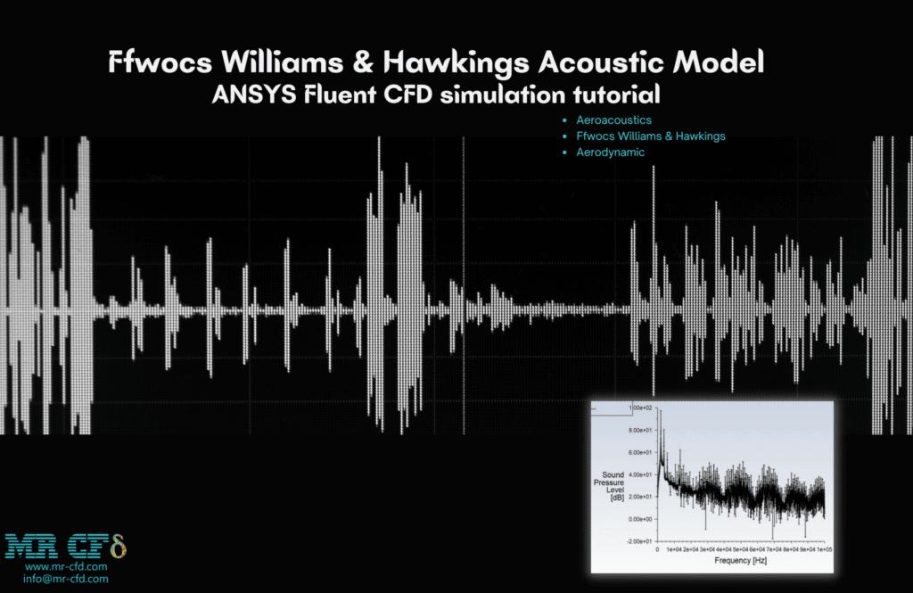
After the simulation, the sound pressure level, A-weighted, and acoustic pressure readings recorded by the defined receivers are extracted. The graph of acoustic pressure is constructed with time as the variable of interest. The data were initially transferred to the frequency domain using the Fourier transform. This was the first step. You can see the information about the acoustic signal plotted in dB in the frequency domain in the graph that the results produce (which is called the sound pressure level plot). The graph shows that the frequency band below 2e+4 hertz, where the microphone positioned at the receiver’s site picked up the most sound, is the most active.
A-weighting is a well-established standard curve that tries to adjust the sound pressure levels measured using a microphone to correspond more closely to how the human ear perceives sound. This graph also validates the findings from the earlier research, and it is common knowledge that the highest frequency that the human ear can hear at the location of the desired receiver occurred at frequencies lower than 1e+4. There is a clear demonstration of how the acoustic pressure level drops as the distance between the receiver and the acoustic source (cylinder) increase in the data allocated to recording the closer and different receivers.
As an example, the Ffowcs-Williams & Hawkings model is applied to the following simulation:
– Creating the geometry: Using a CAD program or Ansys DesignModeler, you should create the 3D geometry of the cylinder and the domain surrounding it. The geometry should include the borders of the entrance, outflow, and any other elements necessary for the simulation.
– Mesh generation: Creating a high-quality mesh for the geometry using Ansys Meshing as part of the mesh production process. The mesh needs to be of a fine enough size to accurately capture the flow features around the cylinder, particularly in regions close to the walls. You can use prism or inflation layers to refine the mesh close to the wall.
– Boundary conditions: You are responsible for defining the simulation’s border conditions. The outlet boundary condition should be a pressure outlet, and the inlet boundary condition should be a uniform velocity profile. Define the surface of the cylinder as a wall that does not allow sliding, and designate the far-field bounds as pressure boundaries.
– Installation of the LES model: Install and configure the Large Eddy Simulation (LES) model in Ansys Fluent. Select the Smagorinsky model to represent the turbulent viscosity, then determine the time step size and the maximum Courant number that can be used. Choose the Ffowcs Williams-Hawkings (FW-H) model to represent the acoustic behavior of the instrument.
– Solver setup: Here, you will configure the solver so that it can run the simulation. Select the solver based on pressure, then configure the residuals’ convergence conditions. It would help if you used the second-order upwind scheme to discretize the convective terms. It would help if you used the second-order central difference scheme to discretize the diffusion terms.
– Post-processing: You can use Ansys Fluent or another program to post-process the simulation results. Calculate the relevant aerodynamic and acoustic quantities, such as the lift and drag coefficients, the pressure distribution, and the sound pressure level.
In conclusion, to do an acoustic CFD simulation using LES in Ansys Fluent for airflow over cylinders in 4 distinct places, one must pay great attention to the Design of the geometry, the production of the mesh, the setting of the boundary conditions, the setup of the LES model, the setup of the solver, and the post-processing. Accurate and dependable results can be produced for various acoustic and aerodynamic issues, provided that the appropriate setup is used and attention to detail is paid.
Acoustic Investigation (FWH) on a HAWT
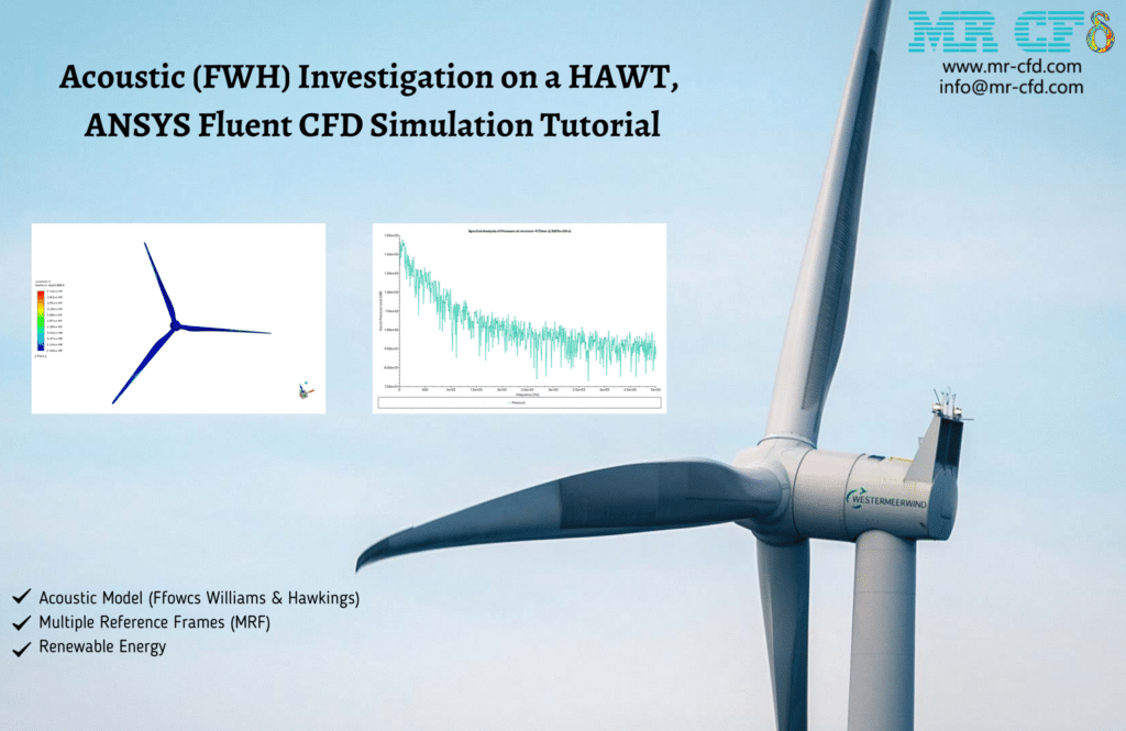
The horizontal axis of this generator revolves at a pace of 72 radians per second as the turbine rotates. At the rate of 15 meters per second, a current of air is moving in its direction. Several places in front of and behind the turbine have been chosen for this experiment. Comparisons have been made between the acoustic parameters used in this Project and those used in another project called “Acoustic (Broadband) Investigation on a HAWT, ANSYS Fluent CFD Simulation Tutorial.”
It is important to note that in this particular model, the points can be formulated in the tab labeled “Acoustic Model-Define Receivers.” In addition, the page labeled “Acoustic Model- Define Resources” allows users to select the wind turbine’s surface as the noise’s origin. The Acoustic Training Course has reached its 5th installment with the release of this product.
In conclusion, the following parameters in the defined places are extracted independently from the solution as part of the Acoustic parameters: Surface dpdt RMS, Static Pressure, Sound Pressure Level (dbA), etc. The value of the Surface dpdt RMS parameter can also be seen to be more prominent in the areas of the edge of the turbine that is further away from the hub. As a result, these areas have a higher magnitude velocity and are also in touch with the wind flow.
You can compare the parameters of this Project and those of the Project given in the description. That Project is based on the same model but solved using the Broadband Model. At long last, the contours, plots, pathlines, and FFTs of the final computation have been completed, and they may now be viewed in figure form.
Broadband Noise Model
In many practical applications involving turbulent flows, noise has no distinct tones, and the sound energy is continuously distributed over a broad range of frequencies. In those situations involving broadband noise, statistical turbulence quantities readily computable from RANS equations can be utilized, in conjunction with semi-empirical correlations and Lighthill’s acoustic analogy, to shed some light on the source of broadband noise.
Unlike the FW-H integral method, the broadband noise source models do not require transient solutions to governing fluid dynamics equations. The source models need what typical RANS models would provide, such as the mean velocity field, turbulent kinetic energy (k), and the dissipation rate (ε). Therefore, broadband noise source models require the least computational resources.
Broadband Noise Sources Acoustic Model
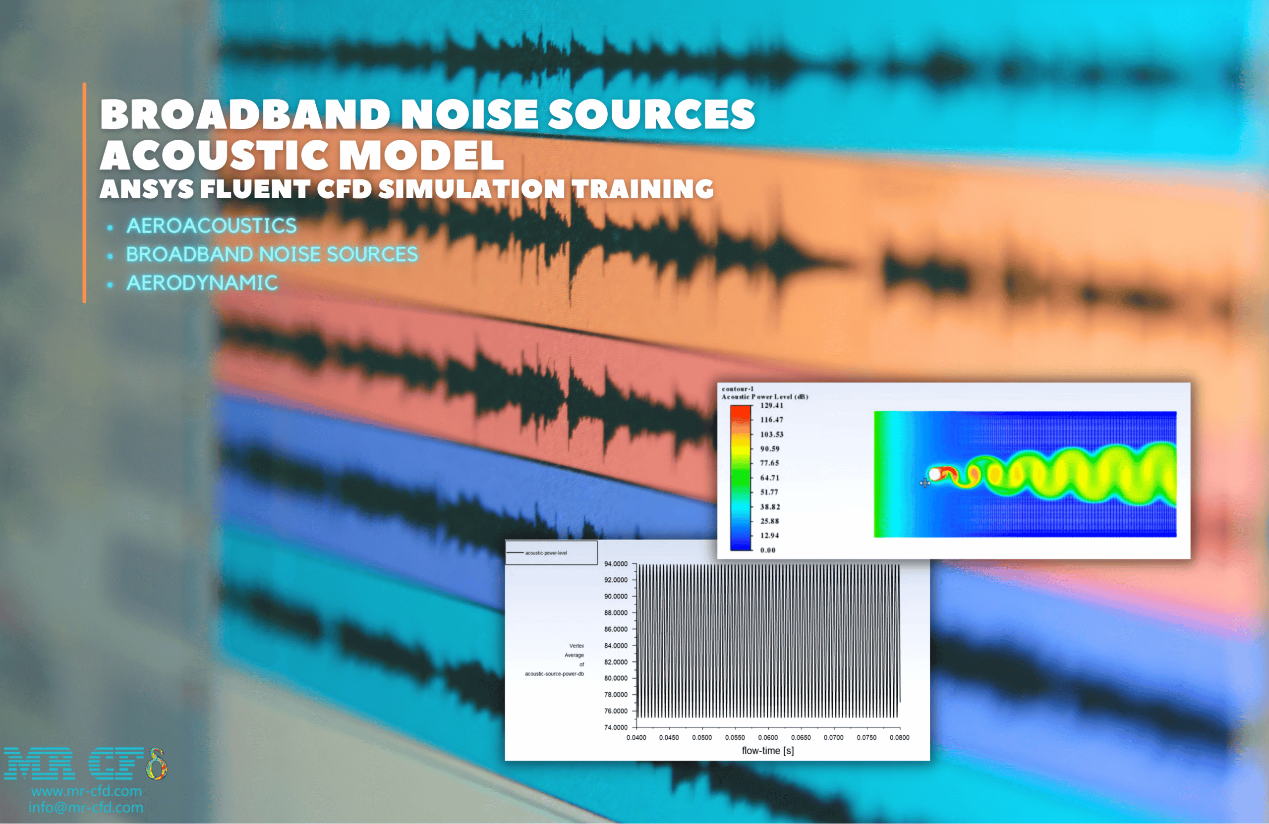
The Broadband noise sources model is used in this study, which involves simulating the airflow around a cylinder to investigate its acoustic properties. The ANSYS Fluent General Training Course is on its tenth episode when it gets to the CFD project. The Acoustic Model Training Course has reached its fourth and final installment with the release of this product.
To simulate the changing behavior of the fluid over time, the simulation uses a transient (unsteady) approach. Because the working fluid cannot be compressed, the sort of solver dependent on pressure is used. In addition to it, broadband noise sources are used.
This is the only model besides the broadband noise sources model that enables us to present a contour based on acoustics characteristics. After running the simulation, the relevant contours were retrieved to make it abundantly evident where the sound pressure level was concentrated. Compared to the dB produced, the maximum acoustic power level contour is 8.74 W/m3, which is a shallow value. This is because even low acoustic pressure levels can result in significant impairments. Because of the shape of the acoustic power level contour, it is easy to observe that the beginning of the back of the cylinder contains the noisiest portion of the entire cylinder.
The outcomes of this simulation include two different contours, referred to as the LEE-Self noise X-source and the LEE Shear-noise X-source. The LEE-Self noise X-source contour demonstrates the amount of noise caused by the flow even when the cylinder is not there, whereas the LEE Shear-noise X-source demonstrates the amount of noise caused by the condition in which the cylinder obstruction is present. It should be no surprise that the figure in the second scenario is noticeably higher. This demonstrates that the turbulent flow going over the cylinder was the primary cause of the noise produced due to this problem.
The following simulation uses the Broadband noise model to capture sound generated by airfoil flight:
Acoustic in a Turbojet Intake Fan
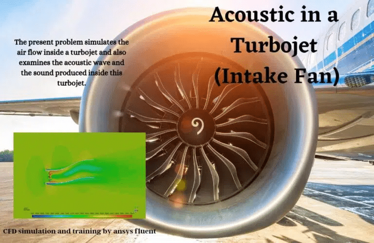
– Creating a high-quality mesh: for the geometry by utilizing Ansys Meshing as part of the mesh production process. The mesh should be fine enough to represent the flow accurately features around the fan, paying particular attention to the regions close to the walls. You can use prism or inflation layers to refine the mesh close to the wall.
– Boundary conditions: You are responsible for defining the simulation’s border conditions. The outlet boundary condition should be a pressure outlet, and the inlet boundary condition should be a uniform velocity profile. Establish the far-field and pressure boundaries, and define the fan surface as a revolving wall.
– Turbulence model setup: The turbulence model must first be configured in Ansys Fluent before further work can be done. Select the turbulence model most applicable to the flow regime, such as the k-epsilon or SST model. Adjust the turbulence scale and intensity such that it corresponds with the conditions at the inflow.
– Acoustic model setup: To begin configuring the acoustic model, open Ansys Fluent and select the Broadband Noise Sources (BNS) model. This model uses a statistical technique to predict the flow’s acoustic sources based on the turbulence’s characteristics. It is necessary to define the relevant parameters for the BNS model, such as the turbulence length scale and the acoustic source strength.
– Solver setup: Here, you will configure the solver so that it can run the simulation. Select the solver based on pressure, then configure the residuals’ convergence conditions. It would help if you used the second-order upwind scheme to discretize the convective terms. It would be best to use the second-order central difference scheme to discretize the diffusion terms.
– Post-processing: You can use Ansys Fluent or another program to post-process the simulation results. Perform the calculations necessary to determine the aerodynamic and acoustic quantities of interest, such as the total pressure and temperature distribution, the mass flow rate, the fan efficiency, and the sound pressure level.
In conclusion, when performing a CFD simulation on a turbojet intake fan, using a Broadband Noise Sources (BNS) model rather than the Ffowcs Williams-Hawkings (FW-H) model for the acoustic model setup requires careful geometry creation, mesh generation, boundary condition setup, turbulence model setup, BNS model setup, solver setup, and post-processing. Accurate and dependable results can be produced for various acoustic and aerodynamic issues, provided that the appropriate setup is used and attention to detail is paid.
Acoustic Investigation (Broadband) on a HAWT
The acoustic performance of a wind turbine as well as the noises that are produced by it at various points across its surrounding area, have been explored through the use of this simulation. With the assistance of the ANSYS Fluent software, the Project is carried out while transitioning.
The horizontal axis of this generator revolves at a pace of 72 radians per second as the turbine rotates. At the rate of 15 meters per second, a current of air is moving in its direction. Several places in front of and behind the turbine have been chosen for this experiment. A comparison was made between the acoustic parameters used in this Project and those used in another project titled “Acoustic (FWH) Investigation on a HAWT, ANSYS Fluent CFD Simulation Tutorial.”
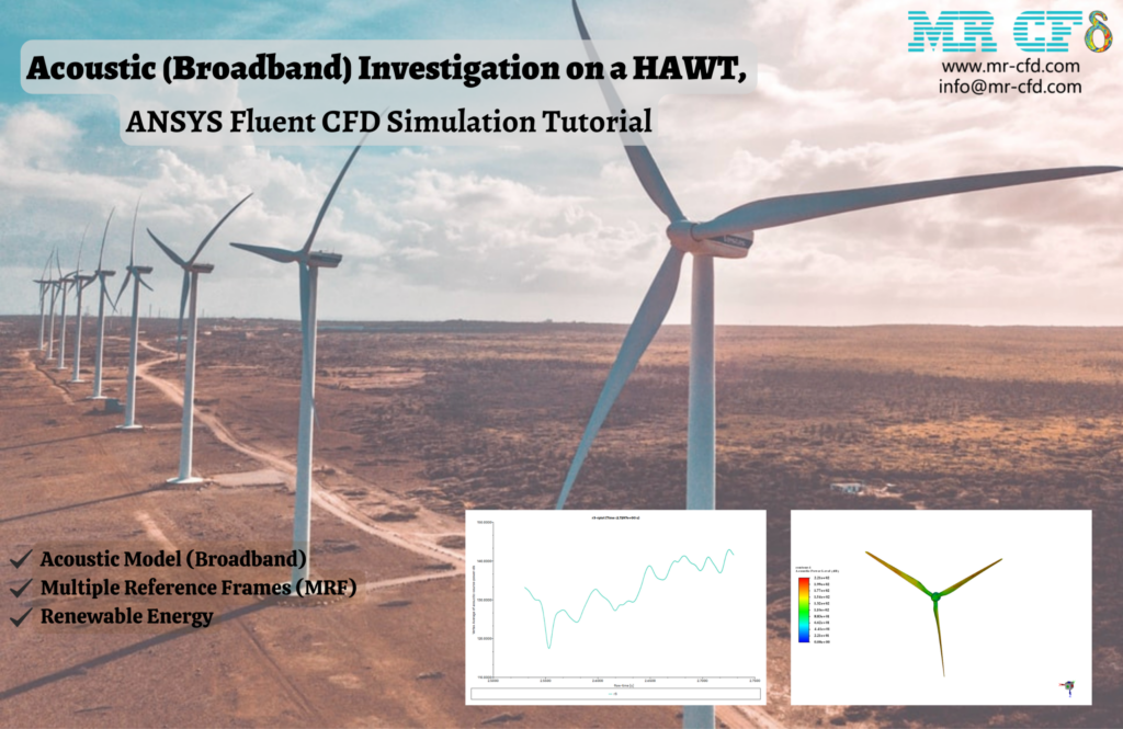
The Acoustic Training Course has reached its sixth installment with the release of this product. In conclusion, the Acoustic parameters of the solution include the following parameters within the domain, or all of the points defined inside the domain are extracted separately:
- The decibel level of the acoustic Power.
- Surface The decibel level of the acoustic Power.
- The density of Power in the Spectrum
- The Self-Noise Source, Created by Lilley…
The quantity of Acoustic Power Level (dB) has dramatically grown on the surface of the turbine due to its movement away from the hub in conjunction with an increase in its magnitude velocity. You can compare the parameters of this Project with those of the Project given in the description. That Project is the same model, but it was solved by applying the Williams & Hawkings Model. At long last, the contours, plots, pathlines, and FFTs of the final computation have been completed, and they may now be viewed in figure form.
Wave Equation Model
Based on the finite volume solver of the wave equation, this model receives information about the sound sources from the calculation of a background flow, which produces sound, similar to the Ffowcs Williams and Hawkings (FW-H) integral model. Unlike the FW-H model, which computes sound signals at specific receiver points, the wave equation model may give a sound field across the whole simulation domain. This concept is comparable to the direct simulation method in this way. In contrast to direct stimulation, the wave equation model lets you view a sound pressure distribution independent of the flow pressure.
The Wave Equation model is being used in this research to simulate water flow around a cylinder to study its acoustic properties. The Acoustic Model Training Course has reached its third and final installment with the release of this product.
To simulate the changing behavior of the fluid over time, the simulation uses a transient (unsteady) approach. Because the working fluid is incompressible, we have utilized a Pressure-based solver type in our analysis. In addition to that, we have used a model based on the wave equation.
After the simulation of the wave equation acoustic model, the sound pressure level measured by the defined receivers is extracted. We have outlined the procedure to export the acoustic source data in the ASD format. The diagram demonstrates that this simulation has been able to capture up to 100,000 different frequencies, and it has been found that the highest sound pressure levels occur at frequencies lower than 10,000.
The wave equation model is used in the following Project:
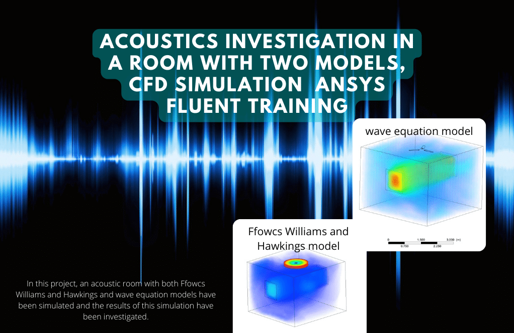
Sound Generation of a Ceiling Fan (FW-H Vs. Wave Equation)
The Sound Generation of a Ceiling Fan in a Room has been Simulated in This Project Using Ffowcs Williams, Hawkings Models, and Wave Equation Models. The ANSYS Fluent software was utilized to analyze the simulation’s outcomes. This CFD project is carried out, and a CFD investigation is carried out.
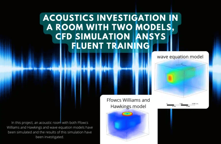
Two different approaches are taken to model the issue. First, the Integral Method developed by Ffowcs Williams and Hawkings is applied, in which the fan turns at 240 revolutions per minute using the Mesh Motion method. A few receiver points at various geographic locations have been identified within the domain.
After that, in the second step, the ceiling fan is stopped entirely so that it does not move at all while the wind speed within the room is increased to 3 meters per second. In this scenario, a Method Based on the Wave Equation is utilized to investigate the noise formation resulting from the wind and fan interaction.
When finding a solution is complete, the results include plots and contours in two and three dimensions related to the room’s pressure, temperature, and velocity. The CFD Post software draws plots of the room sound pressure and amplitude drawn in different points defined by the Ansys Fluent software. The temperature and velocity in the room are displayed as a three-dimensional contour, and characteristics linked to the noises made are accomplished on the fan walls as well as in the room surroundings.
Acoustic Industrial Companies
Many companies specialize in acoustic solutions for industrial applications. Here are a few examples:
– Brüel & Kjær: Brüel & Kjær is a Danish company that offers a wide range of acoustic solutions for industrial applications, including noise and vibration measurement, analysis, and control. They provide hardware and software solutions for the automotive, aerospace, and construction industries.
– Siemens: Siemens is a German company that offers a range of acoustic solutions for industrial applications, including noise and vibration control systems, acoustic materials, and soundproof enclosures. They provide solutions for power generation, transportation, and manufacturing industries.
– Acoustic Control Systems: Acoustic Control Systems is a UK-based company specializing in noise control products and services for industrial applications. They provide solutions such as acoustic enclosures, barriers, and silencers for oil and gas, power generation, and manufacturing industries.
– Noise Barriers: Noise Barriers is a US-based company that offers a range of acoustic solutions for industrial applications, including noise barriers, acoustic enclosures, and soundproof doors and windows. They provide solutions for industries such as transportation, construction, and manufacturing.
– eNoise Control: eNoise Control is a US-based company that provides noise control solutions for industrial applications, including noise measurement, analysis, and control. They offer solutions such as acoustic enclosures, barriers, and silencers for industries such as mining, construction, and manufacturing.
These are just a few examples of the many companies specializing in acoustic solutions for industrial applications. When looking for a company to provide acoustic solutions for your specific needs, it is important to consider factors such as experience, expertise, and reputation in the industry.
MR CFD Industrial Experience in the Acoustic and Aeroacoustic Field
Following is an example of an Aerocoustic industrial project recently simulated and analyzed by MR CFD in cooperation with related companies.
When designing and constructing a toroidal propeller, one of the most important factors to take into account is the acoustic performance of the propeller. The one-of-a-kind propeller form can influence the amount of noise the propulsion system produces. Because of its ring-shaped structure, the toroidal propeller can absorb and dissipate sound waves, which contributes to the propeller’s low noise and vibration levels. This is one of the primary benefits of the propeller. This has the potential to make the journey more pleasant for both the passengers and the staff.
The toroidal propeller, on the other hand, does not produce complete silence. The ring itself can create noise as it moves through the air, and the Design of the propeller itself can create additional noise due to the interaction between the blades and the ring. The acoustic performance of the propeller can also be affected by factors such as the speed of the drone and the presence of external noise sources.
Simulations using computational fluid dynamics (CFD) and experimental testing are two methods that toroidal propeller designers may utilize in optimizing the propellers’ acoustic performance. Adjustments to the Design of the propeller can be made to lower the amount of noise produced and increase its overall efficiency if the propeller’s flow patterns and acoustic properties are analyzed.
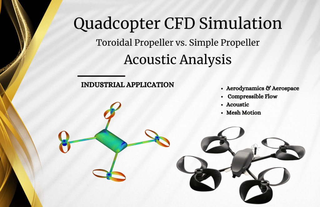
In this Project, we will simulate a drone in a hover posture with a toroidal and standard propeller to absorb the sound level surrounding the domain and generate sound via the propeller. This will allow us to compare the two types of sound generation. We have a quadcopter with four rotors, each rotating at 1200 revolutions per minute.
The ANSYS Fluent program investigates the steady airflow within a three-dimensional drone. The geometry utilized in this simulation was built with software called design modeler. The mesh grid used for both examples was generated with tetrahedral elements using ansys meshing software. The motion of the mesh is used as a model for the propeller in both of these simulations, which are run as transients.
The acoustic performance of quadrotors is critical because it can affect the system’s safety and efficiency. Excessive noise might threaten public safety since it can disrupt communication between the pilot and the ground crew and frighten the nearby animals.
In addition to this, noise can be an indicator of inefficiencies within the system, such as imbalanced rotors or aerodynamic problems. Designers can increase the safety, efficiency, and overall performance of quadrotors by optimizing the acoustic performance of the devices. This can lead to a more reliable and successful usage of quadrotors in various applications, ranging from search and rescue to aerial photography.
During this experiment, a conventional propeller spinning at 1200 RPM created approximately 213 dB of sound. However, this figure drops to 85 decibels when the toroidal propeller is used. The presence of turbulence can significantly alter the noise a propeller produces. The more turbulent the airflow surrounding the propeller, the more likely it is to generate pressure and velocity variations, leading to a rise in noise.
This can be most noticeable in the propeller’s near-field region, an area where the turbulent flow can interact with the structure of the blades and the ring. When trying to maximize the acoustic performance of propellers, designers need to ensure that they consider turbulence.
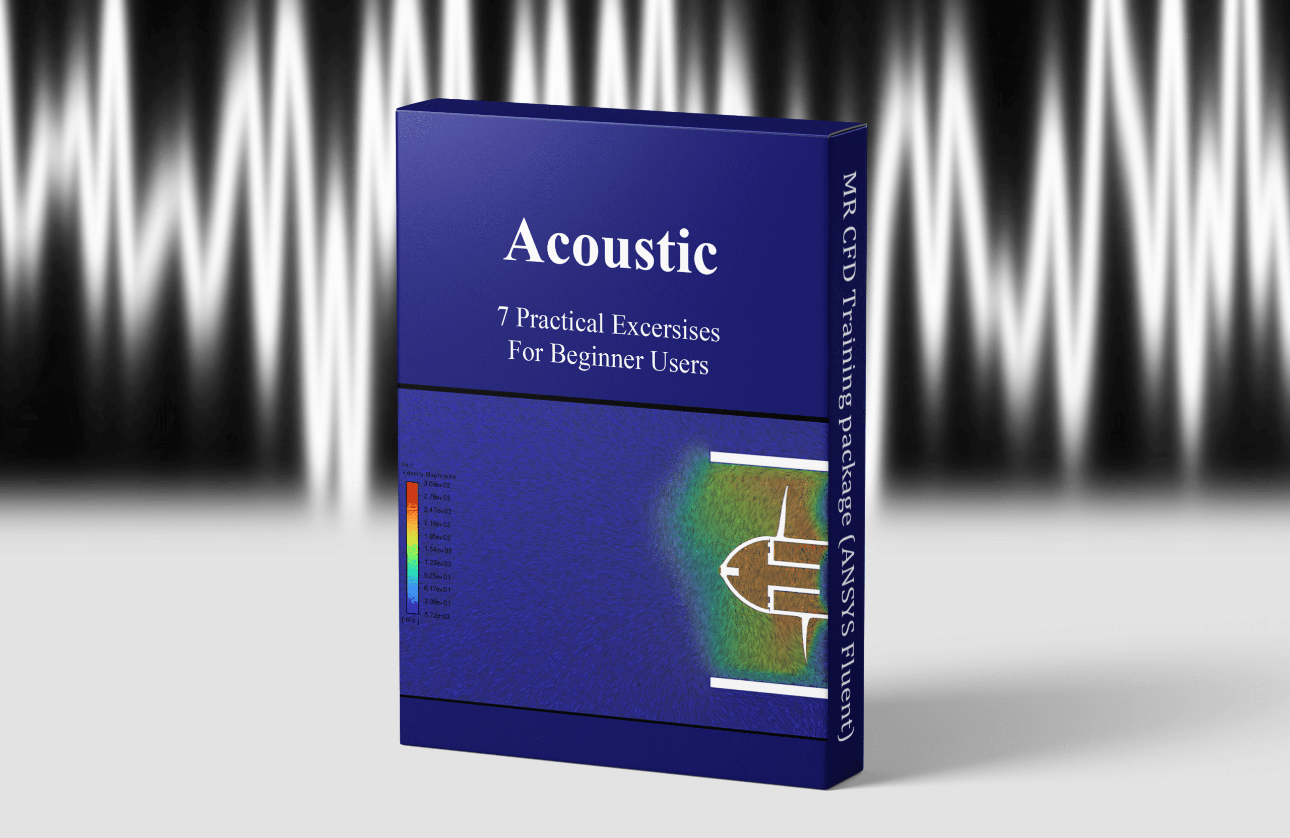
You may find the Learning Products in the Acoustic CFD simulation category in Training Shop. You can also benefit from Acoustic Training Packages appropriate for Beginner, Intermediate, Advanced, and Expert users of ANSYS Fluent. Also, MR CFD is presenting the most comprehensive Acoustic Training Course for all ANSYS Fluent users from Beginner to Experts.
Our services are not limited to the mentioned subjects. The MR CFD is ready to undertake different and challenging projects in the Acoustic and Aeroacoustics modeling field ordered by our customers. We even carry out CFD simulations for any abstract or concept Design you have to turn them into reality and even help you reach the best strategy for what you may have imagined. You can benefit from MR CFD expert Consultation for free and then Outsource your Industrial and Academic CFD project to be simulated and trained.
By outsourcing your Project to MR CFD as a CFD simulation consultant, you will not only receive the related Project’s resource files (Geometry, Mesh, Case & Data, …), but also you will be provided with an extensive tutorial video demonstrating how you can create the geometry, mesh, and define the needed settings (pre-processing, processing, and post-processing) in the ANSYS Fluent software. Additionally, post-technical support is available to clarify issues and ambiguities.
Portfolios
-
Sale
Acoustic CFD Simulation Training Package for Beginners, ANSYS Fluent
Original price was: $900.00.$100.00Current price is: $100.00. Student Discount

