Project Outsourcing
Outsource your project to the MR CFD simulation engineering team. Our experts are ready to carry out every CFD project in all related engineering fields. Our services include industrial and academic purposes, considering the ANSYS Fluent software's wide range of CFD simulations. By outsourcing your project, you can benefit from MR CFD's primary services, including Consultation, Training, and CFD Simulation. The project freelancing procedure is as follows:
An official contract will be set based on your project description and details.
As we start your project, you will have access to our Portal to track its progress.
You will receive the project's resource files after you confirm the final report.
Finally, you will receive a comprehensive training video and technical support.
What is Dynamic Mesh?
The dynamic mesh model can model flows where the domain’s shape changes with time due to motion on the domain boundaries. Combined with the six degrees of freedom (6 DOF) solver, dynamic mesh allows the trajectory of a moving object to be determined by the aero or hydrodynamic forces from the surrounding flow field. In ANSYS Fluent, the dynamic mesh capability is used to simulate problems with boundary motion, such as check valves and store separations. The building blocks for dynamic mesh capabilities within ANSYS FLUENT are three dynamic mesh schemes: smoothing, layering, and remeshing. Combining these three schemes is used to tackle the most challenging dynamic mesh problems. In fact, in problems where the specific region of fluid and its boundaries were displaced during the simulation, a moving mesh should be used to transform and move the cells in the mesh momentarily.
The mesh Smoothing and Remeshing techniques provide instant mesh deformation capability. Remeshing is used when the mesh is more sensitive to mesh changes, which can be used to manually specify ranges of the maximum and minimum Length Scale for mesh changes. Generally, the dynamic mesh technique simulates models that require a moving mesh area. This model enables the spatial variation of the defined areas for fluid flow and allows the mesh of the region at the same time as the spatial location of the points and boundaries of the region changes compatibility with the place at the present moment. The dynamic mesh technique comprises three steps: determining dynamic mesh methods, specifying specific modes with dynamic mesh options, and defining the dynamic mesh zone.
In computational fluid dynamics (CFD) simulations, the dynamic mesh approach simulates the movement of objects or boundaries inside a fluid domain. During a CFD simulation, the fluid domain is partitioned into a mesh of discrete cells or elements. To model the movement of objects within the fluid or to adjust to changes in the fluid domain, the position and shape of the mesh can be altered dynamically while the simulation is running. Dynamic mesh is frequently utilized in simulations of rotating equipment, oscillating structures, or fluid-structure interactions. Additionally, it is employed in simulations of free-surface flows in which the fluid domain’s form changes over time.
In a simulation with a dynamic mesh, the mesh is changed at each time step to account for the motion of the borders or objects inside the fluid domain. This calls for applying specific algorithms to prevent the mesh from degrading and becoming deformed or knotted. Overall, Dynamic Mesh is a robust method that makes it possible to simulate fluid dynamics in complicated systems more precisely and realistically.
How can Dynamic Mesh CFD simulation be applied in Engineering and Industries?
Simulations of fluid flow using dynamic meshes have a wide range of applications in engineering and other fields. The following is a list of various applications that can make use of Dynamic Mesh simulations:
Aerospace and Automotive Industries
In the aerospace and automotive industries, Dynamic Mesh simulations represent the flow of fluids around moving objects like cars, airplanes, and rockets. Among other things, this includes modeling the flow of exhaust gases. It helps examine the aerodynamic performance of the vehicle as well as the vehicle’s stability and the impact of moving parts such as flaps, landing gears, and control surfaces.
FSI Analysis of Airflow around an Airfoil Vibration
The current issue is a Fluid Solid Interaction (FSI) Analysis of Airflow around an Airfoil performed in the ANSYS Fluent software. This method analyzes the airflow around the airfoil. During this simulation, a circular computational domain of airflow will be built. This will be done to place an airfoil within this region. Because of the high speed at which this airfoil travels, the flow of air collides with its body, which causes a force to be applied to it.
In this model, defining the boundary of the inner surface around a circle that is part of the airfoil as fixed support is distinguished from creating a circular hole inside the airfoil itself. This barrier or surface is always impacted by the interaction with the flow of the fluid, but it does not change position or deform due to this interaction. However, because the contact of the fluid flow with the airfoil body causes the two sides of the airfoil to be displaced, these boundaries need to be described as displacement.
To accomplish this, we will need to define a data transfer from the model wall in the fluent software to the same model wall in the transient structural program as Force. This indicates that the fluid flow around the airfoil wall strikes the wall, causing it to be subjected to a force by its proximity to the wall. Additionally, we ought to classify as displacement any data transfer between the model wall in the transient structural program and the same model wall in the Fluent software. This indicates that the wall affects fluid flow in the surrounding area.
In the current modeling, an airflow is modeled by considering a circular computational domain to define it. The inlet boundary of the airflow is specified as the circumference of the computational domain. Consequently, we might say that the fluid and the solid engage in a confrontation in both directions. As a result, the ANSYS Workbench software environment features the utilization of the FSI approach.

To accomplish this, you must define the model in the Fluent and Transient Structural software. After that, you must couple the process of addressing these problems with this system coupling. This is necessary because the geometry is the same in fluid and solid design modes. A link between the geometry of these two programs is something else that needs to be established. This indicates that the connection with solid analysis is the cause of the sudden change in the structure of the mesh.
Finally, data transfer needs to be defined to build a connection or coupling between fluid and solid and specify the effect that each has on the other. In this way, the results of these two solutions in the software programs are sent to each other. As a result, we specify two data transfers in the system coupling section; as a result, we are required to declare this data transfer for a particular area or boundary that extends from a source to a target.
As a result, the velocity inlet boundary condition is utilized at this border to ensure that both the airflow velocity and the airflow directions are adaptable in response to changes in the amount of time. The fact that the direction of the airflow is changeable indicates that the airfoil’s angle of attack will change over time. As a result, the UDF was utilized to ascertain the variable velocity and the varied attack angle.
Because the dynamic mesh is the primary component of the model, we need to employ a transient solver for the simulation process. This is because the dynamic mesh is the primary component of the model. With a time step size of 0.0005 seconds, the simulation process can be completed in the current model in 0.32 seconds.
We define the same amount of time for both the fluid and solid software because the simulation process is performed in both types of software. As a result of the extremely high air velocity, we use a solver based on density. Additionally, the simulation is transient. Following the completion of the solution process, we acquire the results in the software programs Fluent and Transient Structural. On the exterior of the airfoil, we describe deformation, strain, and stress contours using software that calculates transient structural responses.
These contours correspond to the very last second of the simulation, which lasted 0.32 seconds. The fluent program displays two-dimensional outlines related to velocity, pressure, and temperature variables on the computational region’s symmetrical surface surrounding the airfoil. These contours also correlate to the final second of the simulation, which was 0.32 seconds. A figure depicting the drag and lift coefficient changes imparted to an airfoil through time in 0.32 seconds is also presented here.
This Project is connected to the numerical simulation of the cylinder piston motion carried out with the help of the ANSYS Fluent program. Let’s say we have an engine that uses four strokes. Therefore, we shall proceed with a total of four phases. Using the connecting rod, the rotating action of the crankshaft is transferred to the piston, which results in the piston moving in a vertical reciprocating motion within the cylinder. Now, this movement in both directions involves four distinct steps.
The piston that is contained within the cylinder will initially go downward. At the same time, the intake valve begins to open, allowing flow to enter the cylinder. Second, as the cylinder’s piston rises, its flow becomes more compressed. Third, the piston will reach the highest possible position for the explosion. This point is known as the “top dead center.”
At long last, the piston inside the cylinder moves downward once more. At this stage, it is necessary to release the exhaust valve restriction to allow the flow to exit the system. Within the scope of our simulation, we do not plan to study any chemical reactions, combustion, or explosions. The process we wish to depict is the action of the piston moving back and forth inside the cylinder.
To complete this task, we relied on the Dynamic Mesh Model. In general, whenever we have a moving boundary or a deforming zone, we will employ a dynamic mesh. In this case, the surface of a piston moves through a transitional motion inside a cylinder. Consequently, this results in the mesh becoming deformed over time. Because of this, we define the In-Cylinder option to describe the piston’s reciprocating motion when it is contained within a cylinder.
In the in-cylinder model, we determine several parameters, such as the crank radius, the length of the connecting rod, the cutoff point for the piston stroke, and so on. By utilizing the parameters that we set, the Fluent program generates an in-built function that is referred to as full-piston. We define the piston’s movement or the border using this full-piston function. This function takes into account the entire piston.
Now that we have defined the reciprocating motion of the piston surface and intake and exhaust valves, we can move on to the next step. To define motion for these rigid bodies, we need first to define the boundary related to the surface of the piston and the valves as a rigid body. We will use the function of the entire piston as a means by which to define the movement of the piston surface. However, to specify the movement of the intake and exhaust valves, we use profiles that explain the variations in valve lift regarding the crank angle.
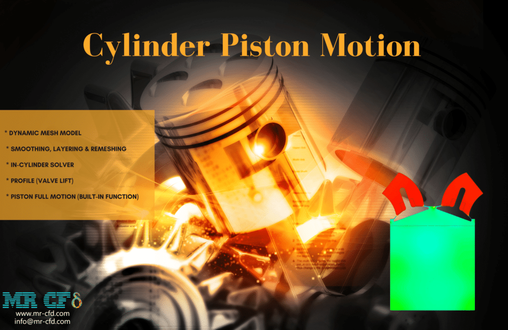
The way flow behaves is reliant on the passage of time because of the nature of this modeling. As a result, we use the unstable solver (also known as Transient). Following the application of the solution, we were able to get pressure and velocity contours. In addition to that, we were able to obtain an animation of the pressure and velocity contours.
The findings indicate that the cylinder-piston system is operating as it should be. The surface of the piston oscillates continuously between being raised and lowered over time. In addition, the intake and exhaust valves are sequentially opened and closed in time with the movement of the piston. At long last, we have an animation demonstrating the immediate modifications to the mesh.
Marine and Offshore Engineering
In marine and offshore engineering, dynamic mesh simulations are used to research how ships, submarines, offshore constructions, and floating platforms respond to different types of waves. It contributes to the optimization of hull designs, the prediction of hydrodynamic loads, and the evaluation of the performance of propellers and thrusters.
Fish Cage Floating on Seawater
Using the Fluid Solid Interaction (FSI) approach found within the ANSYS Fluent program, the current challenge attempts to replicate a fish cage floating on the water’s surface. This CFD project is carried out, and a CFD investigation is carried out. Following the completion of the solution process, we acquire the results in the software programs Fluent and Transient Structural. The final 0.05 seconds of the simulation are relevant to analyzing all the outcomes. We can acquire deformation, strain, and stress contours on the body surface of this fish breeding cage by using software that analyzes transient structural data.
Using the Fluent software, we can acquire two-dimensional contours of velocity, pressure, water volume percent, and air volume fraction on the middle plate (the same as the symmetry plate). In addition, a contour diagram illustrating the amount of pressure exerted on the surface of the body of this fish breeding cage is presented here.
In addition, attempts have been made to acquire the surface of the wave produced by the seawater and then to represent, in a two-dimensional space, the pressure, velocity, and velocity vectors present on that surface. Additionally, the waves that open channel wave BC produced are observable, which can be observed in the volume fraction contours. As an additional point of interest, the thin bars connecting the top and bottom holders exhibit the most significant distortion.
Self-Propelled Submarine Motion, Dynamic Mesh (6-DOF)
Using the dynamic mesh approach and the ANSYS Fluent software, the current problem attempts to replicate the movement of a self-propelled submarine while it is floating on the water’s surface. In this simulation, a computational domain that considers air and water at a particular level are constructed. As a result, an autonomous submarine is depicted as floating on the ocean’s surface.
After finding a solution, we are presented with contours in two dimensions related to the velocities and volume fractions of each air and water phase in the floating submarine zones. In the final second of the simulation process, we exhibit these outlines in two different planes: the X-Y plane and the Y-Z plane. In addition, we present a diagram that illustrates the amount of transitional and rotational movement the submarine exhibited along each of the three axis (X, Y, and Z).
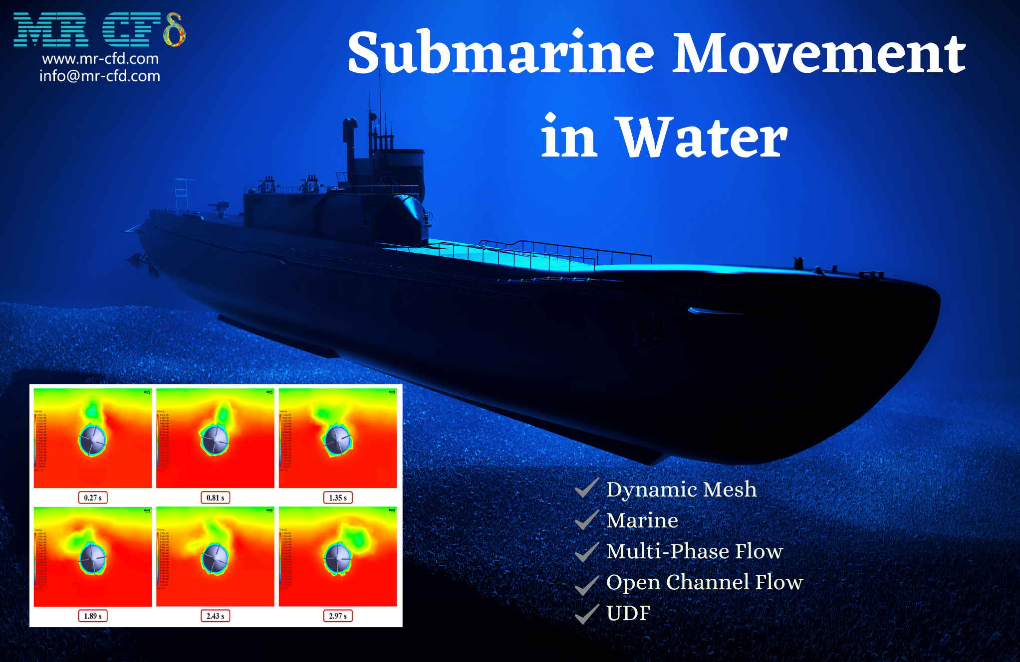
Submarine Movement in Water by Dynamic Mesh (1-DOF)

For this simulation, a submarine was first conceived. Then, a computational domain consisting of two phases of air and water was built to surround the submarine. After finding a solution, we are provided with two-dimensional contours related to the velocity and volume percentage of each of the water and air phases, in addition to two-dimensional path lines located in the areas around the submarine.
We get these contours by plotting them locally on a plane parallel to the Y-Z plane and perpendicular to the submersible’s horizontal axis. These contours are shown to the user throughout the simulation process. The submarine is said to revolve about its center axis (x-axis) by the UDF, and this rotational motion is said to have clockwise and counterclockwise reciprocating motions over time.
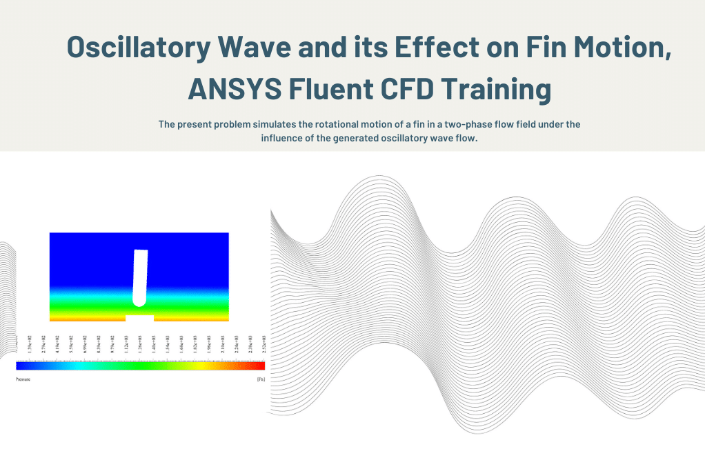
Oscillatory Wave and its Effect on Fin Motion
Using the ANSYS Fluent software, the current challenge attempts to model the rotating motion of a fin as it moves through a two-phase flow field while being affected by a constructed Oscillatory Wave flow. This CFD project is carried out, and a CFD investigation is carried out.
The VOF model is used to define the two-phase flow that is present in this problem. The two phases that make up this flow are air as the primary phase and water as the secondary phase, and the two phases do not interact with one another or pass mass between themselves. A wave of oscillation is produced in the water flow due to the interaction of air and water flow inside the primary domain and the movement of the rigid wall and the walls attached to that moving boundary.
The oscillating wave produced by the flow exerts shear stress and compressive Force on the fin linked to the floor of the domain. Because of this, the fin behaves like a stiff object and rotates on its vertical axis due to the water forces pressing on it. Because of the nature of the challenge, which required displacement at the model boundaries, a dynamic mesh technique was employed to define the fluid flow. This was done to ensure accuracy.
In addition, a user-defined function, or UDF for short, specifies the reciprocating motion of the scaffold wall responsible for producing the waveform inside the domain. The simulation was run for one hundred seconds, with each time step lasting 0.001 seconds. Following the completion of the solution process, we got two-dimensional contours associated with pressure, velocity, the volume fraction of liquid and air, and pathlines at the time t=2s.
Additionally, the location of the fin in terms of its x and y coordinates and its angle placement at various periods can be saved as a data set in a text file if the write motion history option in the six degrees of freedom definition section is enabled. The data graph presents the angular shifts in the fin’s position over 22.5 seconds.
FSI Analysis for a Ball in Water Flow
The current problem involves simulating the movement of a spherical ball in water using the FSI method and the ANSYS Fluent software. To construct areas with dynamic mesh, the pipe area is specified as being fixed, and the wall surrounding the ball is established through system coupling with transient structural software. This indicates that the location of the water flow within the pipe remains unchanged about the ball and that the ball does not move or rotate while it is contained within the water flow.
Following the completion of the solution process, two-dimensional contours related to the speed and pressure around the spherical body in the center plate of the tube, as well as two-dimensional contours related to the pressure and shear stress on the surface of the body of the spherical body, are acquired. These contours are located on opposite sides of the tube. These contours represented the very last second when the simulation was run. The structural analysis portion also derives contours related to deformation and elastic strain.
Floating Vessel Motion in Water
Using the dynamic mesh approach and the ANSYS Fluent software, the current problem attempts to model the movement of a floating vessel while it is immersed in water. A computational domain consisting of water and having a specific height level is designed for this simulation. A floating vessel is placed on the surface of the water.
Six degrees of freedom (6-DOF) have also been employed to characterize dynamic mesh behavior. The model can relocate itself and move in any one of six different transitional and rotational orientations. The simulation is run with a time step of 0.01 seconds using the present model, and the process takes 7 seconds to complete.

These contours represented the very last second when the simulation was run. Also acquired is the graph that depicts the amount of vertical movement of the vessel along the z-axis about the passage of time, as well as the graph that depicts the amount of rotation angle of the floating vessel about its central axis about the passage of time along the y-axis.
These graphs depict the angular and transitional spatial changes during 7 seconds. Since it is evident that the amplitude of the oscillation of the changes in the two graphs reaches its minimum in the seventh second, we can state that the rotational and the transition motion are both damped after this point. In addition, the figure demonstrates that the position of the floating vessel in the seventh second at the coordinates z = 0.021 and an angle of Y_theta = -1.338 is the point at which stability is achieved.
The ANSYS Fluent software is being used to simulate the fluid flow around two cubes falling into water for this Project. The simulation is being done using the dynamic mesh method. This CFD project is carried out, and a CFD investigation is carried out. After finding a solution, the computational domain will include two-dimensional contours associated with velocity, pressure, turbulent viscosity, and streamlines.
As can be observed from the outlines, the pressure along the length of the cubes’ movement has grown as a result of the sloshing phenomenon as well as the movement of the cubes themselves. Due to the flow separation caused by the movement of the cubes in the fluid, the pressure is at its highest and lowest points in the vertical lengths of the cubes. This is because the sharp corner of the tank and the cubes are near one another.
The kinetic energy contour also reveals that the average kinetic energy attributable to vortices around the cubes, which are vortices created as a result of the movement of the cubes in the fluid, is more significant than in other places. The movement of the cubes has caused the flow to become increasingly turbulent, which has led to the formation of vortices. The wake zones are pretty straightforward when we look at streamlines and vectors.
Energy and Power Generation
Dynamic Mesh simulations are utilized in designing and analyzing turbomachinery, such as turbines, compressors, and pumps, which generate energy and power. It is helpful in the analysis of fluid flow, the enhancement of performance, and the assessment of the effects of moving components.
This Project is connected to the numerical simulation of the Lobe Pump with the program ANSYS Fluent. A pump is a mechanical device for transporting and transferring liquids from one location to another. In this manner, pumps cause liquids to travel to a higher height (by increasing the head) and even lower (such as tanks) by increasing the pressure.
The pump transfers the mechanical energy from an external source, such as an engine, to the fluid moving through it. Because of this, the fluid’s total energy is increased once it is released from the pump.
Dynamic and displacement are two ways to transfer energy to the pump fluid. As a result, pumps can be classified as either positive displacement pumps or dynamic pumps, often known as non-positive displacement pumps. There are two types of positive displacement pumps: rotary (gear, lobe, and vane pumps) and reciprocating (piston and diaphragm pumps).
When looking to boost the hydraulic power of a fluid, one of the most typical types of pumps to use is a lobe pump. Lobe pumps transport liquids via lobes. These pumps are very similar to gear pumps, except that the lobes are designed to virtually meet one another instead of touching and turning against one another.
The two lobes of a lobe pump rotate in opposing directions to achieve pumping action. When two lobes come into contact, fluid might become trapped between them. When the lobes are rotated to a position where they are no longer in contact with one another, high-pressure fluid is rotated through the lobes and out the outlet.
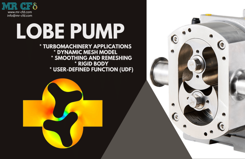
Following the application of the solution, we retrieved the vectors and contours of the velocity and the pressure. We were able to collect the velocity and pressure contours, as well as an animation of the velocity vector, as a result of the lobes rotating over time.
The findings indicate that the lobe pump is operating as it should. This pump can move the fluid effectively while also increasing the pressure of the fluid. The fluid is confined inside the space between the gears in contact. After then, a high amount of pressure is applied in the direction of the outflow, and this fluid is forced there.
This Project is connected to the numerical simulation of the Gerotor Pump carried out with the assistance of the ANSYS Fluent program. A pump is a mechanical device for transporting and transferring liquids from one location to another. In this manner, pumps cause liquids to travel to a higher height (by increasing the head) and even lower (such as tanks) by increasing the pressure. The pump can convert the mechanical energy from an external source, such as a motor, to the fluid moving through it. Because of this, the fluid’s total energy is increased once it is released from the pump.
Dynamic and displacement are two ways to transfer energy to the pump fluid. As a result, pumps can be classified as either positive displacement pumps or dynamic pumps, often known as non-positive displacement pumps. There are two types of positive displacement pumps: rotary (gear, lobe, and vane pumps) and reciprocating (piston and diaphragm pumps). A gerotor pump is one of the most common types of pumps that can be used to improve the hydraulic power of a fluid. Gears are used in gerotor pumps to propel liquids.
Gerotor pumps are comprised of two gears, which turn in the same direction; hence, one gear is housed within the other. When the teeth of two gears come into touch with one another, fluid can become trapped. Due to the rotation that causes the teeth to become spaced apart, high-pressure fluid is spun through the ribs and out the outlet. Internal gear pumps and gerotor pumps share many similarities, with one key distinction between the two. Internal gear pumps, known as gerotor pumps, do not have a crescent on the shaft.
Within the scope of this research, we attempted to recreate the water flow within a gerotor pump. Our goal is to create a model depicting the rotation of two gears inside the pump. The revolution of the gears causes a momentary shift in how the fluid behaves within the pump. As a result, the mesh that makes up the computing domain changes shape over time.
Following the application of the solution, we retrieved the vectors and contours of the velocity and the pressure. Because the gears rotate over time, we obtained the velocity and pressure contours and an animation of the velocity vector. The findings indicate that this gerotor pump is functioning expectedly. This pump can move the fluid effectively while also increasing the pressure of the fluid. The fluid is confined inside the space between the gears in contact. After then, a high amount of pressure is applied in the direction of the outflow, and this fluid is forced there.
This Project is connected to the numerical simulation of the Internal Gear Pump that is done with the software known as Ansys Fluent. A pump is a mechanical device for transporting and transferring liquids from one location to another. In this manner, pumps cause liquids to travel to a higher height (by increasing the head) and even lower (such as tanks) by increasing the pressure.
The pump can convert the mechanical energy from an external source, such as a motor, to the fluid moving through it. Because of this, the fluid’s total energy is increased once it is released from the pump. Dynamic and displacement are two ways to transfer energy to the pump fluid. As a result, pumps can be classified as either positive displacement pumps or dynamic pumps, often known as non-positive displacement pumps. There are two types of positive displacement pumps: rotary (gear, lobe, and vane pumps) and reciprocating (piston and diaphragm pumps).
When looking to boost the hydraulic power of a fluid, one of the most typical types of pumps to use is a gear pump. Pumps that use gears to transfer liquids are called gear pumps. These gear pumps are constructed with a combination of internal and external gears of varying sorts.
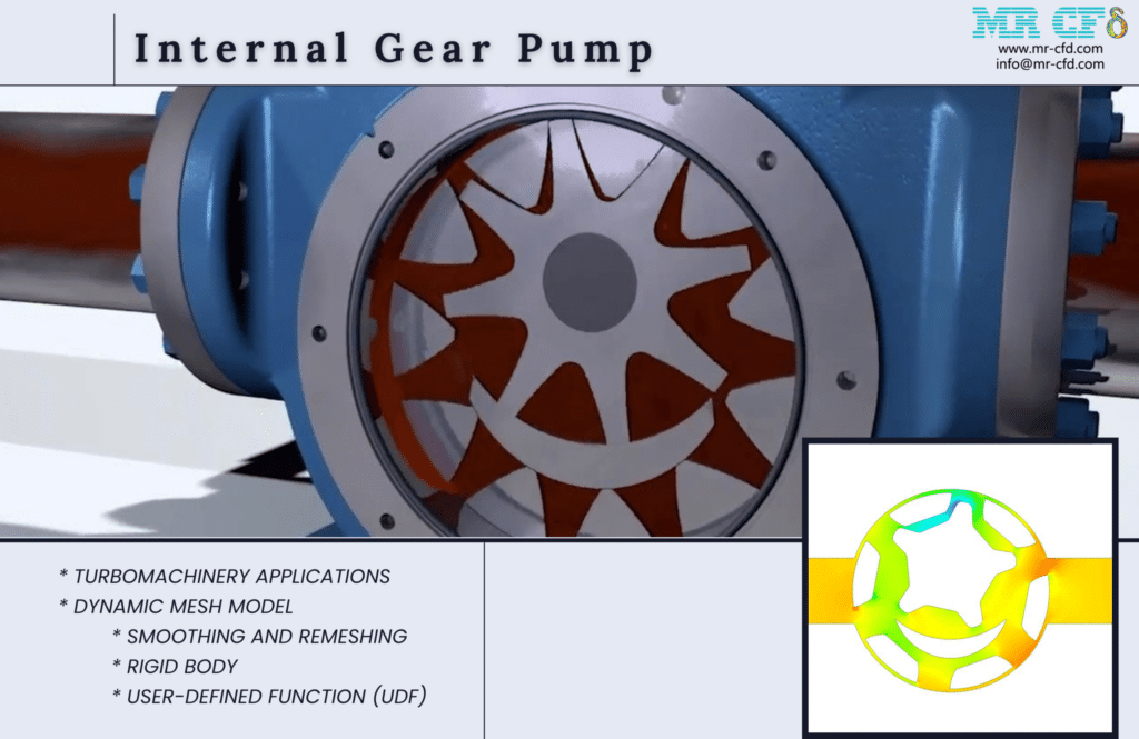
In these internal gear pumps, the flow direction to the output is directed by a crescent between the inner and outer gears. Following the application of the solution, we retrieved the vectors and contours of the velocity and the pressure. Because the gears rotate over time, we were able to obtain an animation of the velocity and pressure contours.
The findings indicate that the gear pump in question is functioning appropriately. This pump can move the fluid effectively while also increasing the pressure of the fluid. The fluid is confined inside the space between the gears in contact. After then, a high amount of pressure is applied in the direction of the outflow, and this fluid is forced there.
This Project is associated with the numerical simulation of an External Gear Pump carried out with the ANSYS Fluent software. A pump is a mechanical device for transporting and transferring liquids from one location to another. In this manner, pumps cause liquids to travel to a higher height (by increasing the head) and even lower (such as tanks) by increasing the pressure. The pump draws mechanical energy from an external source, such as a motor, and transfers that energy to the fluid moving through it. Because of this, the fluid’s total energy is increased once it is released from the pump.
Dynamic and displacement are two ways to transfer energy to the pump fluid. As a result, pumps can be classified as either positive displacement pumps or dynamic or non-positive displacement pumps. Positive displacement pumps are the more common type. There are two types of positive displacement pumps: rotary (gear, lobe, and vane pumps) and reciprocating (piston and diaphragm pumps).
When looking to boost the hydraulic power of a fluid, one of the most typical types of pumps to use is a gear pump. Pumps that use gears to transfer liquids are called gear pumps. These gear pumps are constructed with a combination of internal and external gears of varying sorts.
Two gears, one on each side of the pump, turn in the opposite direction to create an external gear pump. When the teeth of two gears come into touch with one another, fluid can become trapped. Due to the rotation that causes the teeth to become spaced apart, high-pressure fluid is spun through the ribs and out the outlet. The flow of water inside an external gear pump was modeled for this Project by our team.
Our goal is to create a model depicting the rotation of two gears inside the pump. The revolution of the gears causes a momentary shift in how the fluid behaves within the pump. As a result, the mesh that makes up the computing domain changes shape over time. Following the application of the solution, we were able to get pressure and velocity contours. We obtained the animation of the velocity and pressure contours because the gears rotate over time.
The findings indicate that the gear pump in question is functioning appropriately. This pump can move the fluid effectively while also increasing the pressure of the fluid. The fluid is confined inside the space between the gears in contact. After then, a high amount of pressure is applied in the direction of the outflow, and this fluid is forced there.
This Project is connected to the numerical simulation of the Diaphragm Pump that was carried out with the ANSYS Fluent program. A pump is a mechanical device for transporting and transferring liquids from one location to another. The pump can convert the mechanical energy from an external source, such as a motor, to the fluid moving through it. Because of this, the fluid’s total energy is increased once it is released from the pump.
Dynamic and displacement are two ways to transfer energy to the pump fluid. As a result, pumps can be classified as either positive displacement pumps or dynamic pumps, often known as non-positive displacement pumps. There are two types of positive displacement pumps: rotary (gear, lobe, and vane pumps) and reciprocating (piston and diaphragm pumps).
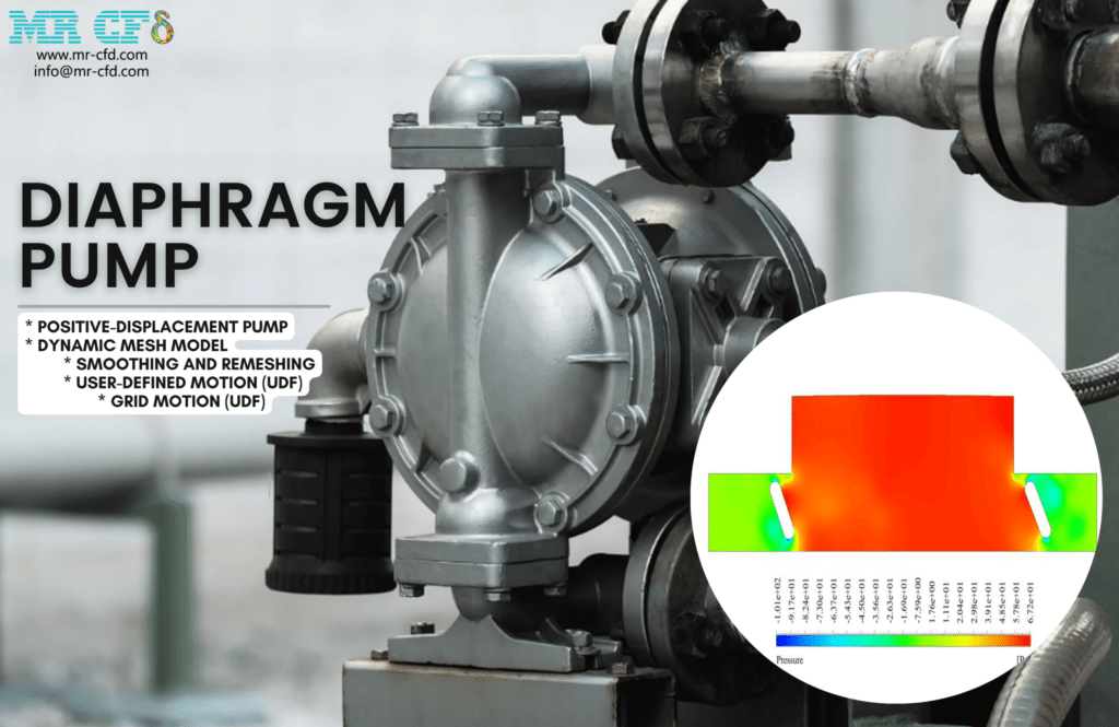
Within the scope of this research, we attempted to recreate the water flow within a diaphragm pump. We aim to create a model that accurately depicts the rotary motion of the membrane inside the pump. The fluid’s behavior within the pump is momentarily altered due to the gears’ reciprocating action. As a result, the mesh that makes up the computing domain changes shape over time.
Following the application of the solution, we were able to get pressure and velocity contours. We obtained an animation of the velocity and pressure contours by considering the membrane’s movement over time. The findings indicate that the pressure and velocity are subject to continuous change due to the non-stationary membrane moving in a reciprocating motion. The reciprocating motion results in suction being drawn through the intake valve and compression being drawn through the output valve.
Biomedical Engineering
In the field of biomedical engineering, dynamic mesh simulations are utilized in the process of designing medical devices as well as researching how fluids move through biological systems. It assists in analyzing blood flow via arteries, heart valves’ functioning, and fluids’ interaction with medical devices.
Manufacturing and Process Industries
Dynamic Mesh simulations are utilized in the manufacturing and process industries to optimize production processes such as injection molding, casting, and extrusion. It assists in evaluating the flow behavior, cooling rates, and the interaction of fluids with moving parts.
Environmental and Renewable Energy
Dynamic Mesh simulations explore wind flow patterns around wind farms, tidal turbines’ behavior, and fluid flow’s impact on environmental systems. These studies are carried out in the context of environmental and renewable energy. It helps optimize systems that use renewable energy and understand the environmental impact.
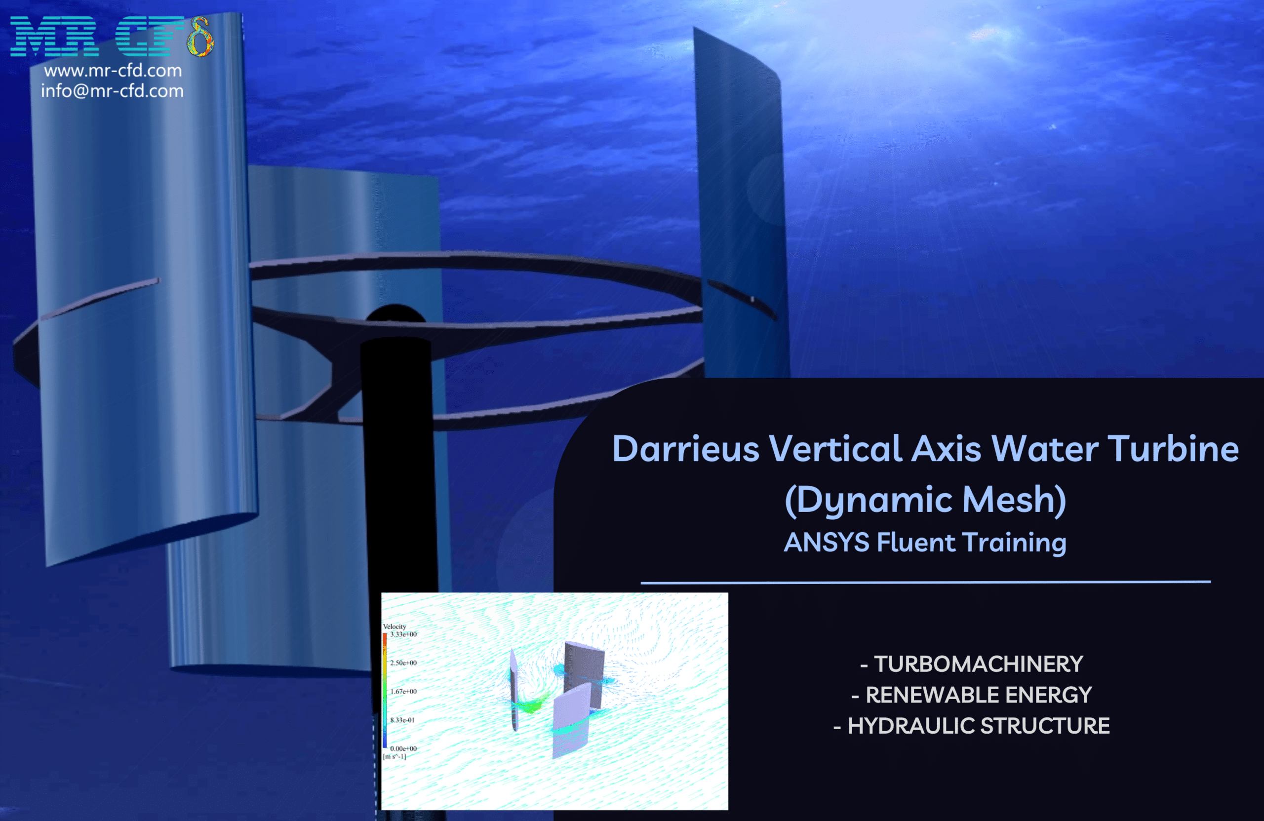
Darrieus Vertical Axis Water Turbine
Using the Dynamic Mesh approach in the ANSYS Fluent program, the challenge simulates water flow around a vertical axis water turbine (VAWT) submerged in water. The water turbine belongs to the class of vertical axis turbines and is of the Darrieus type. As a result, the axis of the turbine is oriented in a manner that is perpendicular to the direction in which the water is flowing.
For this simulation, a turbine with a vertical axis and three blades will be placed inside a rather ample computational space containing solely water flow. After finding a solution, we are provided with two-dimensional contours that relate to velocity, pressure, and kinetic turbulence energy, in addition to path lines and velocity vectors on a plane that passes through the center of the turbine. In addition to that, the turbine’s torque and its other performance aspects are examined.
The Darrieus wind turbine is a form of vertical axis wind turbine (VAWT), a device that generates electricity by utilizing wind power. The generator is made up of several curved aerofoil blades that are installed on a rotating shaft or support structure. Because of the curvature of the blades, the blade can only be stressed in tension when the spinning speed is very high.
The blades of a Darrieus turbine can be twisted into a helix. For example, a Darrieus turbine might have three blades with a helical twist of sixty degrees. This characteristic, which takes advantage of the fact that the wind pushes each blade around on both the windward and leeward sides of the turbine, distributes the torque uniformly over the entirety of the rotation, preventing harmful pulsations.
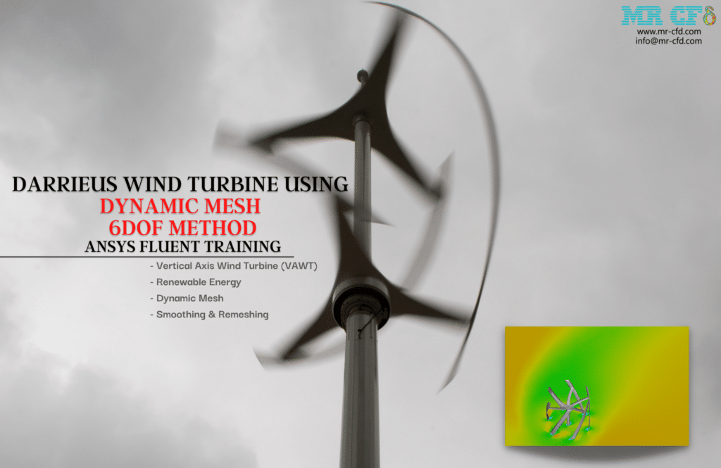
The provided pressure contour illustrates not only the pressure changes in the domain but also the pressure changes in the surroundings around the blades. In addition, the leading edge of the turbine wall is subjected to the most severe pressure gradient, which makes sense given that the velocity has recently reached a standstill.
In addition, the streamlined vectors demonstrate the quality of the flow streams resolved in the wake section, which is the primary obstacle that must be overcome in aerodynamic modeling. The ensuing turbulence is depicted quite precisely by the turbulence contour that has been presented.
These are just a few examples; Dynamic Mesh simulations can be used in a wide variety of other industries and engineering domains where it is essential to comprehend and optimize the behavior of a system to account for the movement of objects or boundaries within a fluid domain.
MR CFD services in the Dynamic Mesh Engineering and Industries
With several years of experience simulating various problems in various CFD fields using ANSYS Fluent software, the MR-CFD team is ready to offer extensive modeling, meshing, and simulation services. CFD Simulation Services for Dynamic Mesh is categorized as follows:
- Six DOF dynamic mesh for modeling variation of location and angle of ship and boat in wavy sea situation
- Simulation of the tidal turbine using six DOF dynamic mesh methods (calculating rotation speed)
- Releasing of food boxes from airplanes using six DOF dynamic method
- Simulation of globe valve movement during the time
- Train movement in the tunnel by variable velocity function in an urban tunnel
- Simulation of flap movement of an airplane wing
- Falling boxes into the water tank
- Modeling the underwater vehicle in Submerged and non-submerged situations
- Solid fuel combustion and modeling solid height level during burning fuel
- Fluid solid interaction of blood flow and vessel
- FSI simulation of blood flow pumping in a human heart
- Fluid solid interaction of airflow around the building and finding final deflection and fluctuation (two-way and one-way FSI)
- Two and four-stroke internal combustion engine
- …
This Project is connected to the numerical flow simulation that was performed through the Check Valve utilizing the program ANSYS Fluent. A check valve is a unidirectional valve that allows fluid to flow in only one way while completely blocking flow in the other direction.
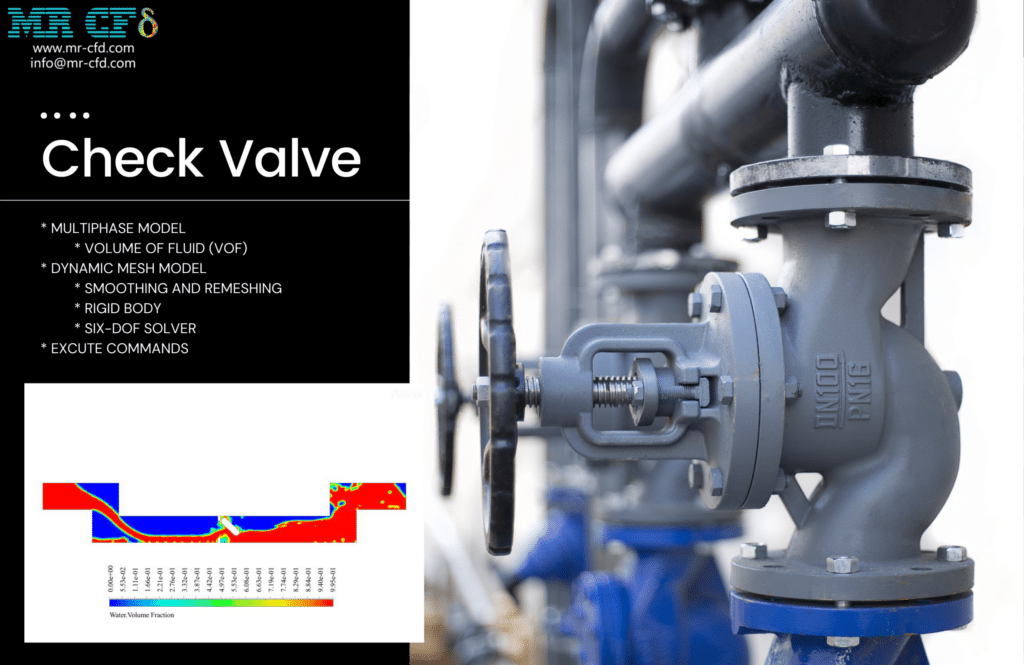
Modeling the action of the check valve inside the pipe is the goal of this research. The mesh of the computational zone is subjected to deformation over time due to the opening and closing of the valve inside the tube. Following the application of the solution, the contour of the mass fraction of water was obtained. In addition, we successfully obtained a moving picture of the mass fraction of water.
The findings indicate that the mechanism of the check valve is operating appropriately. First, the water flow enters the previously empty pipe, and then the valve opens because of the Force applied to it. After that, the flow of water that is coming in is stopped. Applying pressure to the valve to stop the flow of return water leads the valve to close.
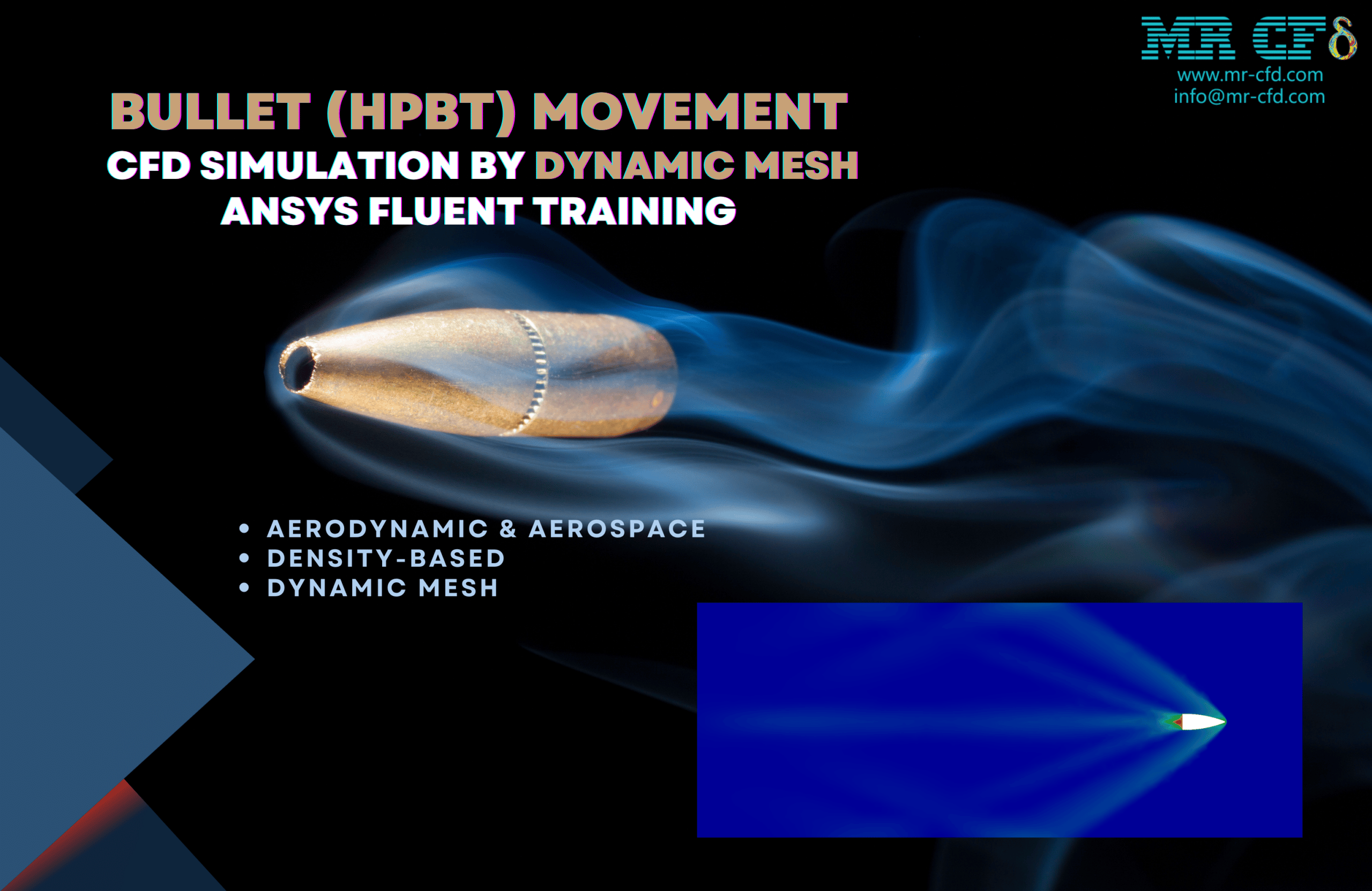
The hollow point boat tail bullet is commonly used in rifles designed for long-range large-game hunting. A few distinct approaches to modeling moving objects within the ANSYS Fluent Software exist. A model known as the dynamic mesh is one in which the components of the domain continually reform, perish, and are formed over time. Compared to stationary models in which the objects remain in the same place while the flow changes, this model is more tangible.
This Project involves the development of a two-dimensional high-pressure ballistic tip ammunition that operates in a rectangular space at a velocity of 2,850 feet per second. The movement of the bullet is simulated using the Dynamic Mesh model, in which the elements are meshing with one another at each time step. When modeling the compressibility of the air over the bullet, the Density-Based option is used. This option models the air properties by employing an ideal gas material to determine the air properties.
The ANSYS Fluent General Training Course is on its 11th episode when it gets to the CFD project.
When finding a solution is complete, you will have two-dimensional contours of the variables pressure, temperature, and velocity. In addition, the elements can be seen once every five-time steps and undergo deformation at the beginning of each time step. In contrast to the other models offered by the ANSYS Fluent program, the bullet is the one that is traveling while the air remains still. Significant changes occur in the air pressure and velocity behind the bullet after it breaks the sound barrier as a direct result of the shock wave produced when the sound barrier is broken. Exhibited is an animation connected to the movement of the bullet in response to changes in the velocity of the domain.
Dynamic Mesh MR CFD Projects
The computational fluid dynamics (CFD) simulations provided by Dynamic Mesh can be utilized in various applications and fields of study. The following are some examples of projects that have been simulated using Dynamic Mesh CFD:
Aircraft Wing Morphing: Simulation of the aerodynamic behavior of an aircraft wing that can change shape while the aircraft is in flight is referred to as “aircraft wing morphing.” Simulations with Dynamic Mesh can be used to analyze the morphing mechanism’s influence on the wing’s aerodynamic performance and help optimize it.
Valve Dynamics in Internal Combustion Engines: Research into the motion and behavior of intake and exhaust valves in internal combustion engines is called “valve dynamics.” Simulations made with Dynamic Mesh can help analyze the valves’ dynamics, improve valve timing, and determine the effect on engine performance.
Fluid-Structure Interaction (FSI) in Biomedical Applications: Modeling the interaction between blood flow and the flexible artery walls in cardiovascular systems. The behavior of blood vessels can be better understood using Dynamic Mesh simulations, which can also be used to improve stent designs and investigate the effects of vascular illnesses.
Wave Energy Converters: Research the efficiency of devices that draw power from ocean waves (also known as “wave energy converters”). The design of the converters can be improved through Dynamic Mesh simulations, which can also be used to analyze the device’s interaction with waves and evaluate the efficiency of power generation.
Fluid-Structure Interaction (FSI) in Offshore Structures: Researching how ocean waves interact with offshore structures, including oil platforms and floating wind turbines. The structural response of offshore structures can be analyzed using Dynamic Mesh simulations, which can also help improve design parameters and evaluate the effect of waves on the stability and performance of offshore structures.
These are just a few examples; Dynamic Mesh CFD simulations can be applied to a wide variety of other applications, particularly those in which the motion of boundaries or objects within a fluid domain is essential to comprehending and optimizing the system’s behavior.
Dynamic Mesh in Industrial Companies
MR CFD has worked with clients in these industries, giving them helpful insights and advice for optimizing their systems using Dynamic Mesh modeling methods. Companies in the manufacturing sector that perform fluid flow simulations and analysis frequently employ a method known as dynamic mesh. It makes it possible for the computational mesh to deform or move while the simulation is running so that an accurate representation of the shifting geometry or fluid domain may be obtained.
Industrial companies frequently use dynamic mesh techniques in a variety of applications, including the following:
Automotive Industry: In the automotive industry, the dynamic mesh can mimic the flow around moving components of cars, such as rotating wheels, oscillating pistons, or moving valves. This technique is beneficial in the design of new vehicles. The aerodynamic performance, engine efficiency, and cooling system performance can all be improved due to this.
Aerospace Industry: In the aerospace industry, the dynamic mesh helps model the flow around aircraft components such as flaps, landing gears, or control surfaces that move while the aircraft is in motion. It helps to understand how these moving pieces impact the aerodynamic performance and the vehicle’s stability.
Energy Sector: In the energy field, the dynamic mesh is used to analyze the flow of fluids in power generation systems like gas turbines and wind turbines. The research of the behavior of spinning components, the optimization of efficiency, and the analysis of cooling systems are all facilitated by their use.
Chemical and Process Industry: In the chemical and process industries, the dynamic mesh is used to mimic the flow of fluids in equipment such as reactors, mixers, and other machinery that contains moving elements. It makes it possible to investigate the kinetics of reactions, the mixing effectiveness, and the heat transfer rate.
Biomedical Engineering: In biomedical engineering, the simulation of blood flow in arteries, heart valves, or other anatomical components that go through deformation during the cardiac cycle makes use of approaches that involve dynamic meshes. This contributes to a better understanding blood flow patterns, which helps identify possible problems and create medical devices.
These are just a few examples of how industrial organizations use dynamic mesh. This method provides a potent instrument for precisely simulating fluid flow in systems with moving or deforming components, paving the way for more realistic and illuminating analysis.
MR CFD Industrial Experience in the Dynamic Mesh Field
Some examples of a Dynamic Mesh industrial project were recently simulated and analyzed by MR CFD in cooperation with related companies on the MR CFD website.
You may find the Learning Products in the Dynamic Mesh CFD simulation category in Training Shop. You can also benefit from Dynamic Mesh Training Packages Part 1 & Part 2, appropriate for Beginner, Intermediate, Advanced, and Expert users of ANSYS Fluent. Also, MR CFD is presenting the most comprehensive Dynamic Mesh Training Course for all ANSYS Fluent users from Beginner to Experts.
Our services are not limited to the mentioned subjects. The MR CFD is ready to undertake different and challenging projects in the Combustion modeling field ordered by our customers. We even carry out CFD simulations for any abstract or concept Design you have to turn them into reality and even help you reach the best strategy for what you may have imagined. You can benefit from MR CFD expert Consultation for free and then Outsource your Industrial and Academic CFD project to be simulated and trained.
By outsourcing your Project to MR CFD as a CFD simulation consultant, you will not only receive the related Project’s resource files (Geometry, Mesh, Case & Data, …), but also you will be provided with an extensive tutorial video demonstrating how you can create the geometry, mesh, and define the needed settings (pre-processing, processing, and post-processing) in the ANSYS Fluent software. Additionally, post-technical support is available to clarify issues and ambiguities.
