Project Outsourcing
Outsource your project to the MR CFD simulation engineering team. Our experts are ready to carry out every CFD project in all related engineering fields. Our services include industrial and academic purposes, considering the ANSYS Fluent software's wide range of CFD simulations. By outsourcing your project, you can benefit from MR CFD's primary services, including Consultation, Training, and CFD Simulation. The project freelancing procedure is as follows:
An official contract will be set based on your project description and details.
As we start your project, you will have access to our Portal to track its progress.
You will receive the project's resource files after you confirm the final report.
Finally, you will receive a comprehensive training video and technical support.
What is Fan?
A powered device that moves air is called a fan. A fan comprises a spinning arrangement of vanes or blades that affect the air and are often constructed of wood, plastic, or metal. Although the two types of fans might seem to operate the same, there are some significant variances in their construction and performance. Cost is typically the biggest differentiator between the two varieties. General-purpose fans are made for the home or light-duty business sectors and employ the least expensive materials and components. Homes, appliances, and little ventilation systems all employ these fans. Industrial fans are made of more rigid materials and parts to last longer, provide more airflow and pressure, and adhere to stringent environmental and ambient specifications.
Many fans and blowers fall under the classifications of Industrial Fans, Industrial Blowers, Industrial Exhausters, Exhaust Blowers, Industrial Cooling Fans, Industrial Exhaust Fans, Industrial Ventilation Fans, Industrial Centrifugal Fans, and Impeller Fans. They are one of two basic types of industrial fans: Centrifugal, Axial, or mixed-flow.
Axial Fans
Axial fans come in cylindrical wheels with a bushing attached to the impeller that is positioned at an angle to the plane of rotation. Air is trapped between the impeller blades and is forced further axially as they rotate. In the radial direction, the air is rarely moved. The axial fan blades are mostly set directly on the motor shaft. They are used in systems with low air dynamic resistance for air supply and air extraction through openings or combined to a maximum of 3 m air ducts.
Centrifugal Fans
A scroll casing and an impeller make up a centrifugal fan. An impeller is a hollow cylinder with mounted blades secured around the circumference by disk plates. The hub for mounting the impeller on the shaft is in the middle of the strengthening ring. Air is compressed and transported out from the impeller’s center when operating. It is trapped between the blades. Centrifugal force drives air to the scroll case, which is transferred to the exhaust pipe. The centrifugal fans have curved blades that face either forward or backward. Blades that are curved backward can save up to 20% of energy. The high air overload capacity of backward-curved blades is another significant advantage. Although they need a smaller impeller diameter and lower speed, centrifugal fans with forward-curved blades guarantee the same air capacity and pressure characteristics as those with backward-curved blades. So they can get the desired outcome while using less room and making less noise.
Mixed-Flow Fans
An axial-centrifugal fan, a diagonal flow fan, is a mixed-flow fan. It balances airflow and pressure. Mixed-flow fans combine axial and centrifugal properties. It usually has a diagonal or twisted impeller. Cylindrical or conical casings house this impeller. Air enters the mixed-flow fan axially and is directed diagonally or helically by the impeller blades. A fan with axial and centrifugal movement can generate considerable pressure than a typical axial fan while maintaining a high airflow rate.
Higher pressure capability: Mixed-flow fans can create higher pressures than axial fans, making them suited for airflow against moderate resistance or in ductwork systems.
Efficient airflow: Mixed-flow fans’ diagonal or twisted blade shape reduces turbulence and noise compared to centrifugal fans.
Space-saving: Mixed-flow fans are usually smaller than centrifugal fans.
Versatile applications: HVAC, ventilation, cooling towers, heat exchangers, and air handling units use mixed-flow fans.
Mixed-flow fan performance depends on design and manufacturer. See the manufacturer’s specs and instructions for correct mixed-flow fan model information. Centrifugal fans apply in air exhaust and supply ventilation systems with long air ductworks and high air dynamic resistance.
How can Fan CFD simulation be applied in Engineering and Industries?
Engineering and industry use fan CFD simulation for many purposes. Key applications:
Fan Performance Analysis
CFD simulation lets engineers enhance fan performance. It explains fan airflow patterns, pressure distribution, and efficiency. Engineers can increase fan performance by simulating operational situations and settings.
ACSC Performance with Diffuser Orifice Plate
The article “Effects of a diffuser orifice plate on air-cooled steam condenser performance” inspired this 600 MW ACSC system simulation. ANSYS Fluent software validates the numerical CFD simulation results. These systems condense hot steam from the turbine and transport water from the distillation process to the steam turbine pump section to save energy.
The power plant investigated has seven rows of ACSC systems. CFD simulates the fourth row. Each ACSC row has eight fans under two diagonally porous plates. The turbine outlet’s hot, low-pressure steam goes through each pipe and into the diagonal plates on both sides.
Simulation yields 3D velocity, pressure, and temperature contours. The temperature curve reveals that open-air heats the steam pipe for condensation. The graph of volumetric efficacy versus system fan number is also obtained and checked using the source publication. The article discusses Figure 5-c’s diagram. This study examines how open airflow velocity affects volume transfer from cooling airflow to system fans.
To determine the fan volumetric flow rate, a dimensionless parameter is defined. This value is the ratio of the volumetric flow rate transmitted from the fans by the numerical solution to the ideal state volumetric flow rate. The volumetric effectiveness dimensionless parameter is 428 m.s-1, the ideal volume flow rate. The present work and the article show that the answer is accurate and error-free.
HVAC System Design
HVAC system design and analysis use CFD simulation. It helps engineers assess building airflow, temperature, and quality. Engineers can optimize HVAC system performance, ventilation, and energy efficiency by simulating fan-duct-room interactions.
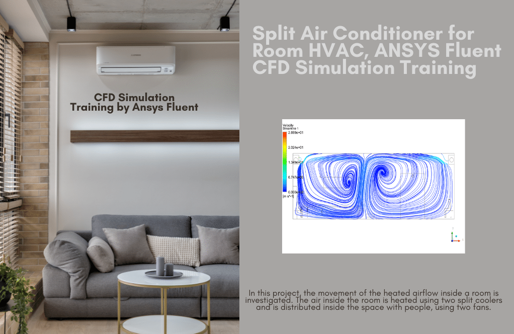
Split Air Conditioner for Room HVAC
ANSYS Fluent software analyzes room-heated airflow in this Project. Two fans transfer warm air from the Split Air conditioner for Room HVAC. We analyze this CFD project. As discussed, free and forced convection cause airflow to move in streamlined contours. Hot air rises due to buoyancy. It will lose temperature and decrease as it rises. This systematic process creates such flow patterns.
Cooling System Design
Radiator Thermal Performance with Fans
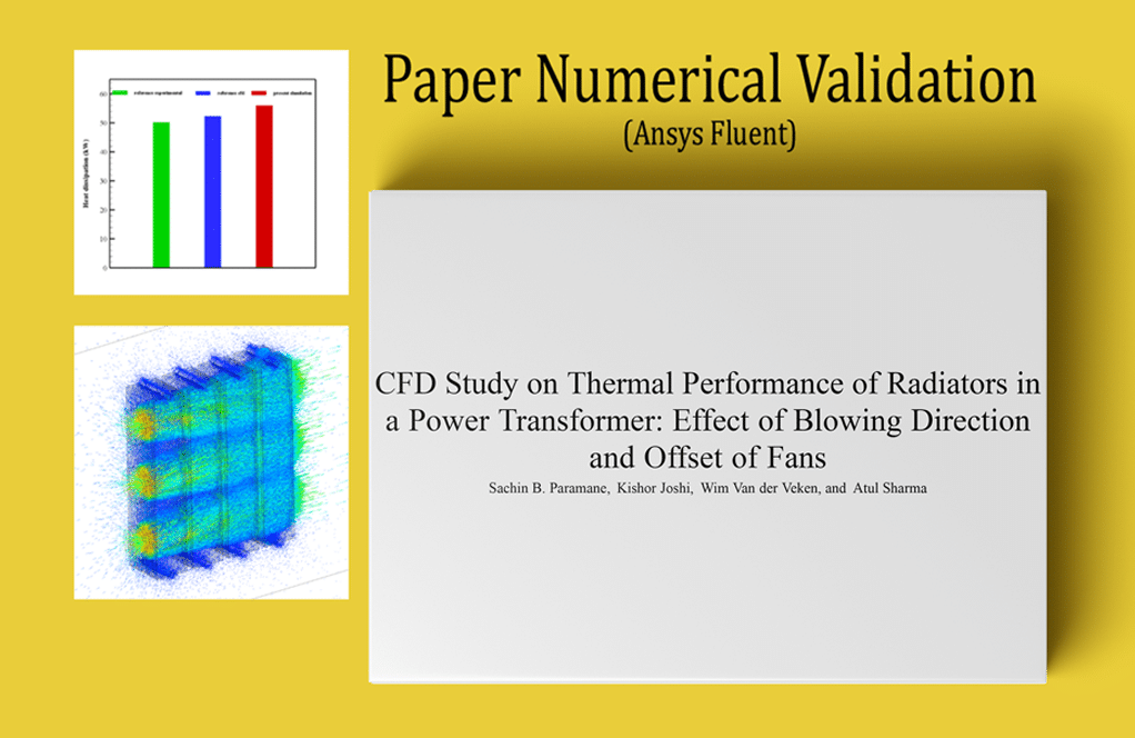
This issue involves radiator heat transfer and airflow simulation. The reference paper “CFD Study on Thermal Performance of Radiators in a Power Transformer: Effect of Blowing Direction and Offset of Fans” was simulated using ANSYS Fluent software. The reference article and recent CFD simulation results are compared and validated. Three horizontal fans power this radiator. Aluminum plates and fins promote heat transfer in this radiator. Four radiator sections each have fourteen rows of plate fins and two hot water transfer pipes at the top and bottom. In the model of horizontal radiators, three fans on the left side of the radiator provide horizontal airflow.
After solving, we determine the net heat loss rate from radiator plates to airflow and compare it to the reference article for validation. Figure 5 of the text and ONAF mode (forced convection heat transfer) are used to compare. The radiator body loses heat at the same rate as the air temperature differential between the intake and outlet. Thus, using the Report and selecting the Total Heat Transfer Rate option from the Flux Report section, we can determine the heat transfer rate difference between the input and output borders. After solving, we get two- and three-dimensional contours of temperature, velocity, and pressure, as well as path lines and velocity vectors.
Industrial Ventilation
CFD simulation optimizes industrial ventilation systems. It helps engineers assess factory, warehouse, and other industrial airflow distribution, pollutant dispersion, and air quality. Engineers can ensure correct ventilation, regulate contaminants, and maintain a safe workplace by modeling fans, ducts, and the environment.
ANSYS Fluent was used to simulate greenhouse air ventilation CFD. We analyze this CFD project. Air velocity and temperature counters are visible after the simulation. Heat transfer from the greenhouse floor raises the air temperature near the floor, lowering its density and making the surrounding air denser. They replenish low air and circulate heat, and the two current fans speed the circulation, repeating the cycle.
Noise and Vibration Analysis
CFD simulation can investigate fan noise and vibration. It helps engineers assess aerodynamic noise and vibration, locate noise sources, and optimize fan designs to reduce noise. HVAC systems in homes and offices require noise reduction.
Ducted Fan: Noise and Thrust Study
This Project resembles a ducted room fan. The study examines acoustic performance. Door flow inlets are 0.5 m/s—the ducted fan’s wall outlet. The fan rotates at 1000 rpm. Two sound sensors in the room measure fan noise. Receivers 1 and 2 are in front of the fan and near the door. The contours show air entering the domain at 0.5 m/s, forming a wake around the fan zone, then leaving. The duct also muffles sound. Thus, receiver 1 has a high sound pressure level, and receiver 2 has a safe range for residents. The A-weighted pressure level supports the assertion, peaking at 80 dB. The thrust force is 54.113455N.
Fan Selection and Sizing

We examine fan heater performance and heated airflow inside a room using ANSYS Fluent software. A fan blows warm air into the room from a heater on one side. We display pressure, velocity, temperature, etc., contours. Due to heated air and movement, the pressure contour around the heater has dropped. Forced and natural convection will lift this heated air. The streamlined contour shows airflow movement due to natural and forced convection, flow pattern, and streamlines. Hot air rises due to lower density. It will gradually cool as it rises. This systematic process creates such flow patterns.
MR CFD services in the Fan Engineering and Industries
Rotating blades or impellers provide airflow in fans. Cooling, ventilation, and air circulation are common uses. Fans move air or gas to adjust the temperature, eliminate pollutants, or improve comfort. With several years of experience simulating various problems in various CFD fields using ANSYS Fluent software, the MR-CFD team is ready to offer extensive modeling, meshing, and simulation services. CFD Simulation Services for Fan is categorized as follows:
Cooling and Ventilation
Electronics, computers, and HVAC systems employ fans for cooling and ventilation. They pull in cooler air and discharge heated air, minimizing overheating and ensuring efficiency.
Air Circulation
Fans promote air circulation in rooms, offices, and warehouses. They evenly distribute air to reduce stagnant air pockets and preserve comfort.

This simulation depicts how air vortices in such a room affect smoke and where to place a couch or sofa. For a closer look, a smoking woman is seated on a bench near the middle of the domain, closer to the exhaust fan. Another woman is standing in front of her with a cigarette in her hand, and a male is talking to them without smoking.
The issue investigates smoke’s pathlines, contours, and vectors in the room. We obtain two- and three-dimensional contours for temperature, pressure, velocity, and smoke mass percentage. Two-dimensional contours YZ and XZ pass through the smoking room’s center. The exhaust and intake fan airflow affects smoke pathlines over time. The results reveal that smoking chamber sofas or seats should be placed closer to the exhaust fan to minimize air vortex. In this simulation, smoke enters the domain simply from cigarette butts, but inhaling could be a relevant parameter in these settings, and we can do it.
Industrial Applications
Fans are essential in factories, power plants, and manufacturing facilities. They control air quality, exhaust ventilation, fume extraction, and air supply.
Personal Fans
Desk, pedestal, and portable fans are used for personal cooling and comfort in homes, offices, and outdoors.
Energy Efficiency
Variable speed settings, optimized blade designs, and energy-saving motors make modern fans energy-efficient. This cuts power use and prices. Fans help cool, ventilate, and circulate air in various personal and industrial environments.
How to Model a FAN inside ANSYS Fluent
With several years of experience simulating various problems in various CFD fields using ANSYS Fluent software, the MR-CFD team is ready to offer extensive modeling, meshing, and simulation services. MR-CFD team is an expert in simulating projects in which axial fans must be simulated. Using this feature, MR-CFD provides customers with a low-cost and straightforward model that can precisely emulate airflow circulation inside a space compared with reality. A fan is considered infinitely thin, and the discontinuous pressure rise across it is specified as a function of the velocity through the fan. The relationship may be a constant, a polynomial, a piecewise-linear, a piecewise-polynomial function, or a user-defined function.
You must be careful to model the fan so that a pressure rise occurs for forwarding flow through the fan. For three-dimensional problems, the values of the convected tangential and radial velocity fields can be imposed on the fan surface to generate a swirl. These velocities can be specified as functions of the radial distance from the fan center. The relationships may be constant or polynomial functions or user-defined functions. Ansys Fluent software has different models for fan simulation, which are introduced below. Each model has advantages and disadvantages that help us choose the best model for the desired simulation.
Fan Boundary Conditions

The fan model does not adequately show the complex flow through the fan blades. Instead, it forecasts how much air will pass through the fan. Fans may be utilized as the only flow source in a simulation or combination with other flow sources. In the latter scenario, the balance between system losses and the fan curve determines the flow rate.
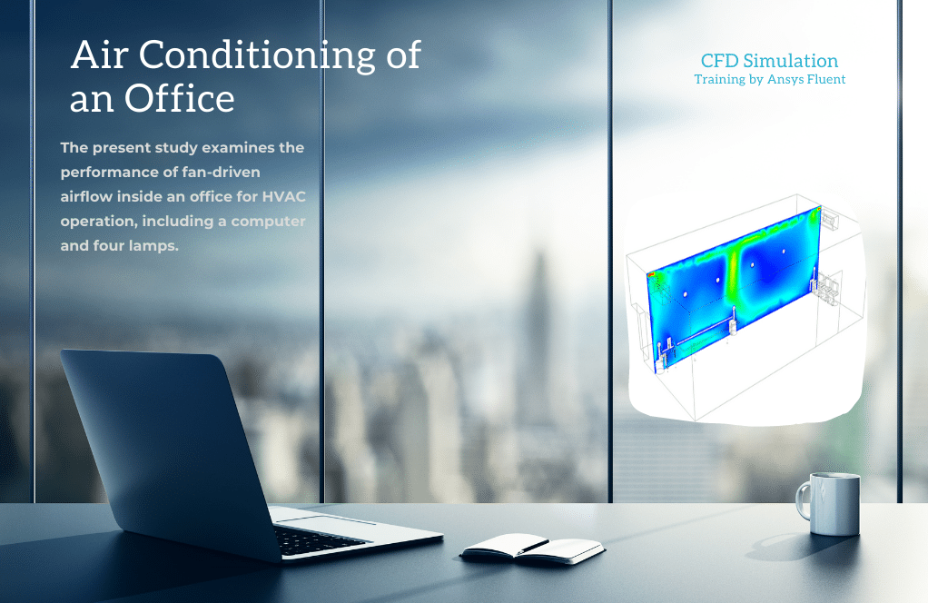
Air Conditioning of an Office by Two Fans
This study replicated fan-driven airflow in an office with one computer and four lamps for HVAC operation. The computer’s plastic heat source is 700 W/m3, whereas each lamp’s glass heat source is 2500 W/m3. Two fans on the top of two office walls bring air into the office. We assumed ambient air convection heat transmission through office doors and windows.
The problem is to study how blown airflow affects office components and humans. Airflow affects model heat sources, which we simulate. Contours and vectors show the two fans’ velocity and thermal performance. ANSYS Fluent program identifies polynomial porous jumps for each fan. Considering several heat sources, these two fans’ HVAC performance for this large office appears adequate.
Exhaust Fan Boundary Condition
An exterior exhaust fan with a given pressure jump and ambient pressure can be modeled using the exhaust fan boundary condition. The boundary condition for exhaust fans only considers momentum, and diffusion processes aren’t recognized. For the flow through the fan to face a pressure rise, you must carefully model the exhaust fan. In the case of reversed flow, the fan is regarded as an inlet vent with a loss coefficient of unity. Exhaust fan Boundary condition is used in the following Project:
Pollution Ventilation in a Subway
ANSYS Fluent simulates subway pollution ventilation. This Project examined subway station air conditioning. The subway station is crowded. This habitat is readily polluted. Simulated pressure, velocity, and pollutant mass fraction contours are 3D. The subway station’s air-conditioning system is ideal based on pollutant contours. Pollutants enter the station through subway doors, but giant air conditioning blowers on the roof move dirty air outside.
Intake Fan Boundary Condition
Intake fan boundary condition options are entirely similar to the exhaust fan ones. Using this BC, an external intake fan can be modeled with a given pressure jump, flow direction, ambient (intake) pressure, and temperature.
Acoustic in a Turbojet Intake Fan
ANSYS Fluent mimics a turbojet’s airflow and acoustic wave and sound. The software studies acoustic waves using the acoustic model. For the current simulation, we show the contour and vector of velocity, pressure, temperature, Acoustic Power Level(dB), and Surface Acoustic Power Level(dB) of the Domain to help understand the problem.
The solution’s acoustic properties become more evident behind the fan and fan wall as the air hits them. The fan surface shows Surface Acoustic Power Level (dB) as a noise source. Finally, the centerline plots of Acoustic Power Level(dB) and Surface Acoustic Power Level(dB) help determine the fan’s acoustic properties.
Mass Flow Inlet/Outlet & Velocity Inlet/Outlet

Engine Room Ventilation System of Ship
ANSYS Fluent simulations of ship engine room ventilation systems. Electric motors power ship compressors, pumps, fans, etc. The engine room takes up the most significant ship space. Heat transmission must be studied because of all the equipment in this space. Engine room and shipbuilding design hinges on the optimal air conditioning system to deliver combustion air to equipment and regulate temperature and humidity. Engineers and academics have constantly sought novel ways to improve ship air conditioning systems. Simulating and analyzing the ship’s engine room ventilation system can assist in discovering novel methods.
Simulation yields temperature, velocity, and pressure contours. Obtain streamline and velocity vectors. Streamlines show that the ventilation system’s cooling air enters and is evenly dispersed. The temperature contour illustrates that motors and diesel engines are hot and cool with cold air.
3d Fan Zone
A distributed momentum source is applied in a fluid volume structured like a toroid to create 3D fan zones, which replicate the action of an axial fan (that is, a blade-swept volume). In contrast, fan boundary conditions (such as an intake-fan boundary zone) are based on a lumped parameter model in which the fan is assumed to be infinitely thin, and a discontinuous pressure rise is described as a velocity function. Also, In contrast to fan boundary conditions, primarily used to model the axial flow and need you to enter swirl and radial coefficients, 3D fan zones can compute swirl and radial velocities.
Smoke Ventilation Using Jet Fan in a Tunnel
Longitudinal ventilation is the most affordable. Jetfoil fans, which induce airflow through the tunnel, are the most common way. Fan air diffuses and provides energy to the tunnel airflow, increasing static pressure. Exhaust ducts remove car and fire smoke and pollutants from the tunnel. Under regular operation, extraction capacity may limit tunnel longitudinal velocity. Tunnel fire pollution control and smoke ventilation are provided by tunnel jet fans, massive axial fans, or a combination.
This effort simulated a car-filled tunnel in 3D. Three pairs of fans at the top of the tunnel suck pollution from hot exhaust gases. Due to its lower density than air, the pollutant rises and leaves the tunnel as the fan blows. Two-dimensional contours of pollution and air pressure, velocity, and volume fractions are obtained after solving. Every five repetitions, contours appear. Fans produce static pressure in tunnels. It streamlines exhaust pollutants and shows fan trajectory.
In conclusion, the mentioned approaches could be carried out to simulate the fan action without the geometry of the fan imported into the solution. In the case of the imported fan blade geometry, MRF, Moving Mesh, and Dynamic Mesh methods can rotate the fan to inhale or intake the air into the desired domain.
Fan MR CFD Projects
Jet Fan Application in a Tunnel Considering a Car Explosion
ANSYS Fluent simulates a tunnel vehicle explosion. This Project assumes a fuel leak and airflow ignite a car. Tunnel-crossing automobile. The explosion caused a tunnel fire and leaked carbon dioxide. Carbon dioxide cannot escape the confined tunnel. It endangers other cars and pedestrians. They employ jet fans on the tunnel roof. Jet fans draw carbon dioxide and other contaminants to the tunnel roof. Jet fans draw in and expel these gases. These jet fans are used to reduce harmful gas emissions.
This modeling assumes a combustion reaction has happened. Thus, merely model carbon dioxide emission from combustion without defining the combustion reaction. 2D and 3D contours of pressure, velocity, temperature, and air and CO2 mass percentage are calculated. The jet fan system is functioning correctly. The back car explosion generates heat and CO2.

Series Fans CFD Simulation using MRF Method
ANSYS Fluent simulates stable air flow between two 3-bladed Series Fans operating at 300 rpm. We analyze this CFD project. The simulation produces two- and three-dimensional contours of pressure, velocity vectors, and streamlines. Fluent calculated the inlet air mass flow rate at 3.62019 kg/s.
The first fan has double the pressure decreases of the second fan. The first and second fans drop 500 and 230 Pa, respectively. The first fan has five times less gauge pressure downstream than the twin fan. Gauge pressure downstream of the first and second fans is -500 and -100 Pa. The first fan has a more significant pressure drop and a higher velocity magnitude downstream (28m/s) than the second fan (12m/s).
Paramotor in paraglider simulation using ANSYS Fluent. A paraglider’s pilot-mounted paramotor propels it. Gasoline-powered engines with fan blades. This simulation uses a 26.85 C cylindrical computational domain for airflow. A pressure boundary condition determines airflow direction at this domain’s inlet and outlet limits. This model uses a fan boundary condition with 383.8-pascal pressure leaps on a surface in the center. The aluminum engine casing with its thermocouple is located behind the fan. The inner wall of the engine is anticipated to be 157 C. This temperature is likely dependent on engine combustion heat. The solution yields 2D and 3D temperature, velocity, and pressure contours. The contours indicate airflow through the fan, air velocities increasing, and considerable pressure variations. The engine’s inner wall heats the area around it.
Fan Stage (Axial Flow) Aerodynamic Performance
ANSYS Fluent replicates stable airflow in a 3D axial flow fan stage. We analyze this CFD project. Pressure, velocity, streamlines, and velocity vectors are simulated in two and three dimensions. Streamlines and velocity vectors show the fluid’s rotating motion due to the rotor domain’s rotation. According to Fluent, the rotor’s greatest diameter’s linear velocity is 31 m/s at 1800 rad/s. TSR (Tip Speed Ratio), the ratio of angular velocity (32m/s) to stator free stream flow velocity (8m/s), is 4. The stator outlet airflow is 16.14 lit/s.
Fan in Industrial Companies
Industrial fans are essential. Industrial fan usage includes:
Ventilation and Exhaust Systems: Industrial facilities need ventilation to control air quality, contaminants, temperature, and humidity. Fans remove toxic air from factories, warehouses, chemical plants, and other industrial settings. They keep workers safe and healthy.
Cooling and Heat Dissipation: Many industrial operations create heat that must be dispersed to prevent equipment from overheating. Fans circulate air to cool machinery, engines, electrical components, and heat exchangers. They optimize operating temperatures and prevent system malfunctions.

Dust and Particle Control: Industrial operations create dust, particles, and airborne pollutants. Fans and filtration systems remove these particles from the air, creating a clean and safe workplace. Mining, woodworking, medicines, and food processing use them.
Drying and Air Circulation: Fans circulate air and remove moisture in drying and curing industries. They speed drying, improve quality, and prevent moisture concerns. Fans help dry and cure textiles, printing, paint, and food.
Combustion and Boiler Systems: Boilers, furnaces, and incinerators need fans. They supply air for efficient and regulated fuel combustion. Fans help maintain the air-to-fuel ratio, maximize combustion efficiency, and reduce pollutants.
Process Cooling and Refrigeration: Industrial operations need cooling to preserve product quality or manage chemical reactions. Fans improve heat transfer in cooling towers, refrigeration systems, and process cooling units. They remove heat from process fluids or equipment to maintain stability and product integrity.
These are some industrial fan uses. Industry, process, and environmental circumstances determine applications and needs. Industrial fans meet airflow rate, pressure, temperature, and efficiency requirements to optimize system performance.
MR CFD Industrial Experience in the Fan Field
Some examples of a Fan industrial project were recently simulated and analyzed by MR CFD in cooperation with related companies on the MR CFD website.
You may find the Learning Products in the Fan CFD simulation category in Training Shop. You can also benefit from the Fan Training Package, which is appropriate for Beginner, Intermediate, Advanced, and Expert users of ANSYS Fluent. Also, MR CFD is presenting the most comprehensive Fan Training Course for all ANSYS Fluent users from Beginner to Experts.
Our services are not limited to the mentioned subjects. The MR CFD is ready to undertake different and challenging projects in the Combustion modeling field ordered by our customers. We even carry out CFD simulations for any abstract or concept Design you have to turn them into reality and even help you reach the best strategy for what you may have imagined. You can benefit from MR CFD expert Consultation for free and then Outsource your Industrial and Academic CFD project to be simulated and trained.
By outsourcing your Project to MR CFD as a CFD simulation consultant, you will not only receive the related Project’s resource files (Geometry, Mesh, Case & Data, …), but also you will be provided with an extensive tutorial video demonstrating how you can create the geometry, mesh, and define the needed settings (pre-processing, processing, and post-processing) in the ANSYS Fluent software. Additionally, post-technical support is available to clarify issues and ambiguities.

