Project Outsourcing
Outsource your project to the MR CFD simulation engineering team. Our experts are ready to carry out every CFD project in all related engineering fields. Our services include industrial and academic purposes, considering the ANSYS Fluent software's wide range of CFD simulations. By outsourcing your project, you can benefit from MR CFD's primary services, including Consultation, Training, and CFD Simulation. The project freelancing procedure is as follows:
An official contract will be set based on your project description and details.
As we start your project, you will have access to our Portal to track its progress.
You will receive the project's resource files after you confirm the final report.
Finally, you will receive a comprehensive training video and technical support.
What is Gas and Petrochemical Engineering?
The production, processing, and transportation of natural gas and petroleum products is the emphasis of Gas and Petrochemical Engineering. It entails the design and operation of machinery and procedures utilized in the manufacture, refining, and distribution of these goods. It also entails the creation of new technologies in order to increase the efficiency and safety of these operations.
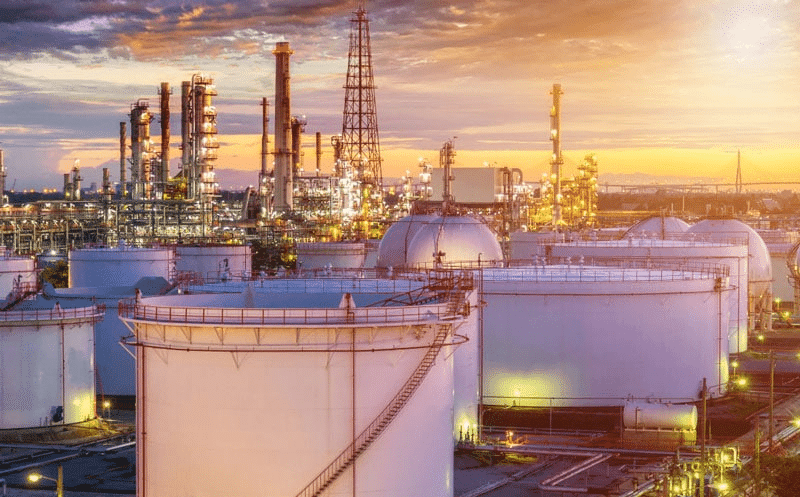
A comprehensive list of petrochemical products would be extended. However, the following are some of the most common petrochemicals utilized by ordinary people, not just industrialists:
- Motor oil
- Gasoline
- Natural gas
- Plastics of all types
- Petroleum jelly
Supercomputers are used by petroleum engineers to evaluate exploration data, model reservoir dynamics, and automate oilfield production and drilling activities.
How CFD simulation can be applied in the Gas and Petrochemical Industries?
In the gas and petrochemical sectors, CFD modeling may be used to study and optimize the performance of numerous processes such as combustion, heat transfer, fluid flow, and chemical reactions. CFD may be used to model gas and liquid movement through pipes, tanks, and other vessels, as well as the mixing of various fluids. CFD may also be used to evaluate the performance of heat exchangers, boilers, and other petrochemical sector equipment. CFD may also be used to optimize the design of petrochemical facilities, assuring their safety and efficiency.
Computational Fluid Dynamics (CFD) is a powerful tool for simulating fluid flow, heat transport, and associated processes in various scientific and engineering issues. Unlike experiments that only allow data to be extracted from a limited number of locations in the system (such as pressure and temperature probes, heat flux gauges, and so on), CFD permits the analyst to examine a large number of areas in the region of interest and generates a comprehensive set of flow parameters for analysis. CFD provides the ability to simulate any physical condition theoretically. As energy demand grows, additional sources are being explored, and drilling operations expand worldwide.
Fluid dynamics are fundamental to most facets of the Petrochemical sector. Although real prototypes are standard for later stages of development, design, and optimization during earlier stages can be significantly accelerated with CFD studies.
Any improvement in drilling, production, or planning can save the operators money. As a result, having a plan and developing an efficient approach ahead of time is critical in the case of costly and uncertain oil and gas well operations. CFD is used in petrochemical engineering applications such as bit performance optimization, convective heat transfer between casings and annular fluids, flow in porous media such as mud filtrate invasion, simulation of multiphase flow for designing separators, cement displacement, erosion prediction, risk analysis during blowout events, drilling hydraulics and hole cleaning optimization. Wellbore stability analysis and cutting transport in the rig.
MR CFD services in the Gas and Petrochemical Engineering and Industries
MR CFD conducted numerous outsourced simulation projects for industrial and research Gas and Petrochemical Engineering applications. With several years of experience simulating various problems in various CFD fields using ANSYS Fluent software, MR CFD is ready to offer extensive services of simulation configurations.
In the gas and petrochemical engineering sectors, MR CFD simulation services may be utilized to examine and optimize the performance of gas and petrochemical operations. Fluid flow, heat transport, and chemical reactions in gas and petrochemical systems may all be studied using CFD models. CFD simulations may also help to improve the design of gas and petrochemical equipment such as heat exchangers, reactors, and separators. CFD simulations may also be used to assess the safety and environmental consequences of gas and petrochemical operations.
MR CFD services in the Gas and Petrochemical engineering field can include a variety of services such as:
CFD on Simulation of Reactors
A chemical reactor is a container in which a chemical reaction takes place. Chemical reactor design encompasses a wide range of chemical engineering concepts. Chemical engineers build reactors to optimize the reaction’s net present value. Designers guarantee that the reaction continues as efficiently as possible toward the intended output product, resulting in the best yield while needing the least money to buy and run. Energy intake, energy removal, raw material prices, labor, and other regular operational expenditures are all included. Heating and cooling, pumping to increase pressure, frictional pressure loss, and agitation is all examples of energy shifts.
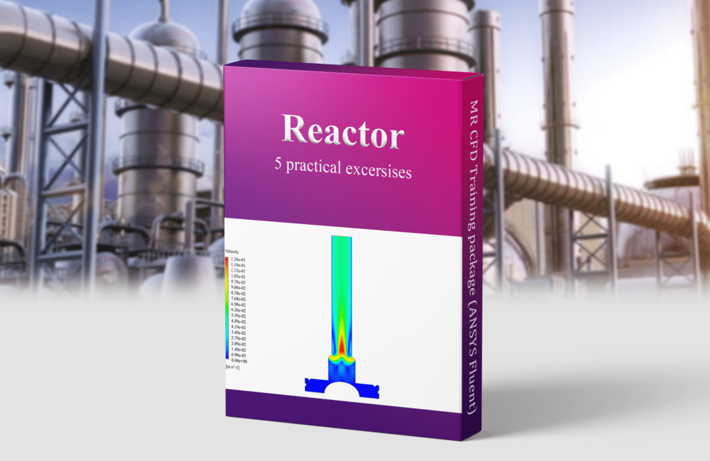
In the MR CFD training package, various types of reactors such as the following are simulated.
- Packed Bed Reactor
- Bioreactor
- Catalytic Reactor
- Plasma Gasification Reactor
- Fluidized Bed Polymerization Reactor
CFD Simulation of Separators Devices
The ANSYS Fluent CFD Simulation Separation Systems Training Package is designed to provide a comprehensive introduction to the fundamentals of CFD simulation with ANSYS Fluent. 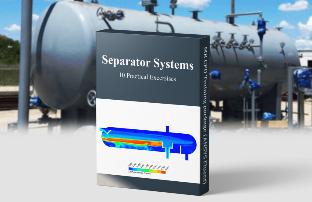
This training package includes ten distinct Separator devices, including:
- Gas Liquid Separator
- Vortex Separator
- Mud and Sand Separator
- Three-Phase Flow Separator
- Hydrocyclone
- Fly Ash Cyclone
- FCC Riser Gas-Solid Separation System
- Reverse Osmosis
- Filter Cake Formation
Hydrocyclone with a Tangent-Circle Inlet CFD Simulation, Paper Numerical Validation
ANSYS Fluent software is used to model the two-phase flow of air and water within a Hydrocyclone in this challenge. The simulation is based on the paper “Effects of curvature radius on separation behaviors of the Hydrocyclone with a tangent-circle intake.” Its findings are compared and validated with those in the publication.
Hydrocyclones are commonly employed in industrial operations for particle separation from a liquid stream. The separation process’s efficiency is greatly reliant on the hydro cyclone’s input design. This study presents a numerical simulation of a hydrocyclone with a tangent-circle intake. The numerical model is evaluated against experimental data and is based on the two-phase Euler-Euler technique. The findings demonstrate that the numerical model can forecast the flow field and particle separation efficiency of the hydrocyclone correctly. The results also reveal that the tangent-circle inlet geometry outperforms the typical circular inlet geometry.
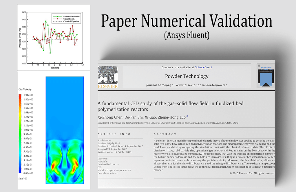
Fluidized Bed Polymerization Reactor, Paper Numerical Validation, ANSYS Fluent Training
Using paper data, this study tries to verify a numerical model of a fluidized bed polymerization reactor. ANSYS Fluent, a computational fluid dynamics (CFD) program, will be used to create the numerical model. To confirm that the model is accurate and dependable, the numerical outputs will be compared to the paper data. The project will also involve ANSYS Fluent training and the creation of a user-friendly interface for the model. The study will give significant insight into the behavior of fluidized bed polymerization reactors and will aid in the improvement of their design and operation.
ANSYS Fluent software was used to simulate a fluidized bed polymerization reactor. This CFD project is carried out and investigated using CFD analysis. A reactor is a device that uses catalysts to execute chemical processes (conversion, composition, decomposition, etc.) that result in the conversion of raw materials into desired products.
Because of the economic aspects of reactor production, it is necessary to design reactors with higher efficiency but lower cost and lower energy consumption; thus, parameters such as volume, temperature, pressure, particle concentration, particle residence time, heat transfer coefficient, and reaction rate are important in reactor design.
Continuous and discontinuous reactors, homogeneous and heterogeneous, pipe and tank reactors, and fixed bed and fluidized bed reactors are all types of chemical reactors. The solids are stationary inside the reactor as a catalyst in fixed bed reactors, and the reactants travel past these materials, reacting and leaving the reactor. The materials in these fluidized bed reactors are reactants or catalysts suspended in the flow under pressure.
The fluidized bed-type reactor has several benefits, including a high heat transfer rate and mass transfer rate, a smaller heat transfer surface, homogeneous temperature distribution, correct temperature management, and complete and quick mixing of reactors and catalysts. The fundamental benefit of a fluidized bed reactor over a fixed bed reactor is the capacity to manage the temperature and avoid the production of hot spots, which is required for any reaction. Fluidized bed reactors have a wide range of industrial uses, including petrochemical, chemical, power generation, incinerators, and so on. This challenge will replicate a two-phase flow inside a basic fluidized bed reactor.
The findings are contrasted and evaluated against those of a publication titled “A basic CFD analysis of the gas-solid flow field in fluidized bed polymerization reactors.” The simulation process is set up so that the solid suspended particles are only up to a height of 20 cm from the chamber floor in the starting state, with a volume fraction of 0.63 within the gas flow. The system’s operating pressure is specified at 1400000 pa.
Gas and Petrochemical Engineering MR CFD Projects
MR CFD is ready to offer extensive modeling, meshing, and CFD simulation services. Following is a brief list of the CFD simulation projects for Gas and Petrochemical Engineering by MR CFD:
Circulating Fluidized Bed (CFB) Gasifier
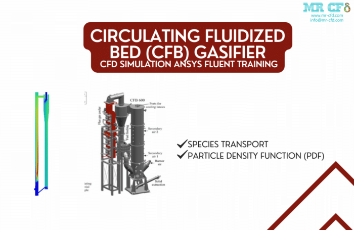
Because of its inherent benefits in high circulating rate, low operating temperature, broad fuel flexibility, and negligible pollutant emissions, the Circulating Fluidized Bed gasifier is popular in commercial applications and academic investigations. A basic CFB cycle was simulated and the results were acquired in this simulation.
The system has two inlets: a vertical inlet for the oxidizer and a horizontal inlet for the fuel; after being mixed, the air and fuel begin flameless combustion in a vertical section and then enter the cyclone to separate unburned ashes as polluted air; unburned fuel circulates to the bottom of the downstream section and enters the process again; and heavy sands and ashes exit from the bottom outlet. In this simulation, the particle density function (PDF) was utilized to model solid dynamics.
Multiphase Flow in Porous Medium, Filter Cake Formation
This training course will offer an overview of multiphase flow in porous media and the generation of filter cakes. The foundations of multiphase flow in porous media will be covered in this course, including the physics of multiphase flow, the governing equations, and the numerical methods used to solve them. The principles of filter cake formation will also be covered, including the physics of filter cake creation, the governing equations, and the numerical methods utilized to solve them. In addition, the course will introduce the ANSYS Fluent CFD simulation program and its capabilities for modeling multiphase flow in porous media and filter cake production. Hands-on exercises will be used to show the usage of ANSYS Fluent for modeling multiphase flow in porous media and filter cake generation.
ANSYS Fluent software is used to model multiphase flow in a porous media. The model is divided into two sections: the upper half of the column contains water-soluble particles, while the lower part of the column contains the porous medium. There is initially a solution with a volume percent of 0.185 of the particles in the water. The soluble particles are separated from the water flow by entering the water flow from the top of the column, providing pressure to the mixture inside the column, and passing through the pores of the porous media.
Combustion Inside the Boiler
This Ansys Fluent CFD simulation training course will show you how to simulate a boiler’s combustion process. You’ll discover how to run the simulation, create the boundary conditions, and analyze the outcomes. You will also learn how to analyze the data and offer recommendations to improve the boiler’s efficiency. The subjects covered in the course will include combustion chemistry, turbulence modeling, heat transport, and radiation. You will have a better grasp of how combustion occurs within a boiler and how to optimize the design for optimal efficiency at the conclusion of the course.
The combustion within the boiler was simulated in this research, and the simulation results were analyzed using ANSYS Fluent software. The current model was created in 3D using SpaceClaim. The boiler is constructed so that airflow comes from the side panel of the boiler, and a combination of fuel flows enters through the thin pipes of the boiler’s lower section, and the boiler outlet is connected to the boiler’s top pipe.
Decomposition of MgO with Argon Gas for Magnesium Particle Production
ANSYS Fluent may be used to model the breakdown of MgO with argon gas for the generation of magnesium particles. Setting up the geometry, establishing the materials, defining the boundary conditions, and executing the simulation are all part of the simulation.
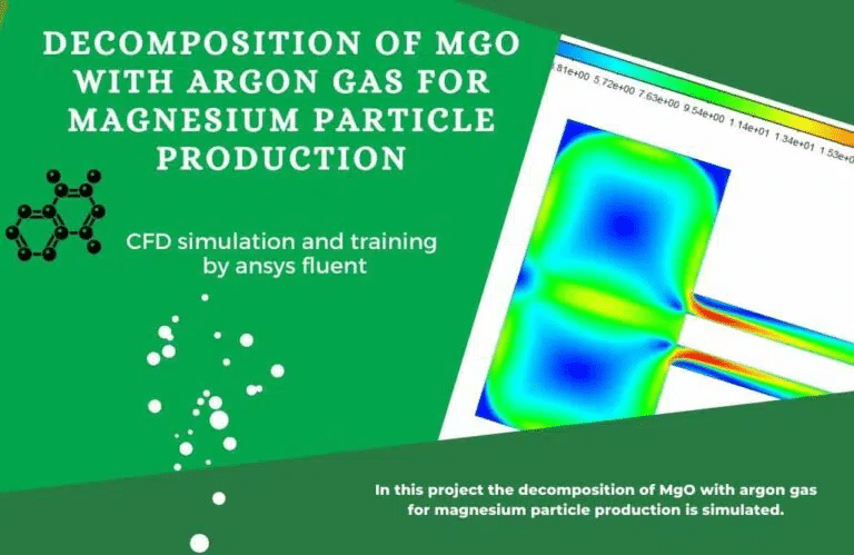
Materials: The simulation’s materials should be defined. This comprises the argon gas, MgO particles, and any other components found in the reactor.
Boundary Conditions: Set up the border conditions to mimic the circumstances in the reactor. This comprises the argon gas’s temperature, pressure, and flow rate, as well as the temperature and pressure of the MgO particles.
Simulation: When the geometry, materials, and boundary conditions have been established, the simulation may begin. This will entail estimating the rate of breakdown of the MgO particles as well as solving the equations of motion for the argon gas and the MgO particles. The simulation results will reveal the rate of generation of magnesium particles, as well as the temperature and pressure of the system.
Thermolysis, or thermal breakdown, is a chemical degradation produced by heat. A substance’s decomposition temperature is the temperature at which it chemically decomposes. Since heat is required to break chemical bonds in the substance being decomposed, the reaction is frequently endothermic. The breakdown reaction of magnesium oxide is endothermic, according to the following equation, and it is accomplished by preheating with argon gas.
MgO(s)→Mg(s)+O2(g)
Accumulation of Particles in Elbow Bend, DDPM
While the DPM technique for CFD solutions has proven to be an efficient way of calculating flow particle-flow studies, it does not produce trustworthy results for dense particle simulations. To address this issue, the DDPM (Dense-Discrete-Phase-Method) is commonly used in CFD projects.
As a result, a thick DDPM model is used. To investigate the current issue, one must solve the flow equations in differential form. We also assume an incompressible and turbulent state within the elbow shape because particle-flow interactions are more likely to produce a turbulent flow condition.
In addition, to account for our boundary layer, we used a Realizable k-epsilon model with a Menter-Lechner wall function. A Transient solution is also used. We tracked the convergence up to a tight residual value of 10-10 in the current investigation. When additional particles were added to the domain, the need to enhance convergence became more pressing due to the increased influence of the source term.
During the solution, the mass average of the source term in the y-direction was also monitored to ensure that each time step met the requisite precision. Following that, the pressure and velocity field findings for both particles and the air-fluid flow are shown below the figures. As can be seen, when the flow approaches the bend portion, the air velocity increases.
Also, the flow temperature is higher adjacent to the hot wall, which is the inner wall, than on the opposite side of the pipe. Also, the heated temperature dispersed over time among the fluid flow and particles. Surprisingly, the DPM particle computations yielded identical results: velocity and pressure were higher at the precise places. Also, the streamlines suggest that numerous vortices occurred at the bend region, which is normally interesting for erosion models.
Minimizing Pressure Drop by Adjoint Solver (RBF)
You may learn how to utilize the Adjoint Solver (RBF) to decrease pressure drop in your CFD simulations with ANSYS Fluent CFD simulation training. The Adjoint Solver (RBF) is a strong tool for optimizing the design of a system by reducing pressure drop. This approach may be used to minimize the amount of energy required to flow fluid through a system, hence lowering the cost of the system. The Adjoint Solver (RBF) may also be utilized to improve system performance by lowering pressure drop and enhancing system efficiency. You may improve the design of your system and lower its cost by learning how to utilize the Adjoint Solver (RBF) in ANSYS Fluent CFD simulation training.
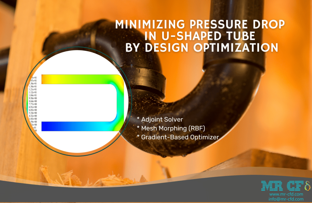
The adjoint solver returns a sequence of data in the form of sensitivity analysis. We concentrate on shape sensitivity. This tool determines which aspects of geometry have the most impact on system performance. As a result, we must define a target parameter. This output parameter is referred to as Observable. We defined the pressure decrease as visible in this study.
As a result, the adjoint solver relies on the pressure drop in the tube. When there is more sensitivity, such as displacement of the border or deformation of the design’s shape, the pressure drop is larger. In the gradient-based optimizer, we employ the sensitivity analysis data. We define how the observable should be altered in this tool. In this project, for example, we investigate lowering the pressure drop. This entails altering the pipe shape to reduce pressure drop. These modifications should result in an ideal design.
Separator CFD Simulation, Three-Phase Flow
CFD Simulation
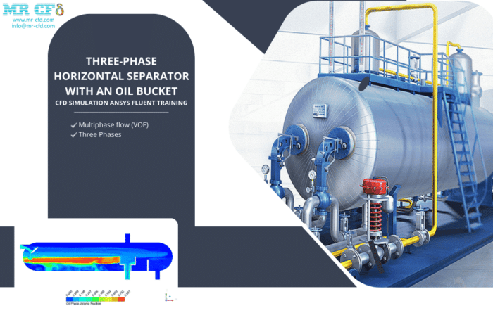
Flow in Three Phases
Three-phase flow is a form of fluid flow in which three separate phases, such as gas, liquid, and solid, are present. This flow is widespread in industrial operations such as oil and gas production, chemical processing, and power generation. CFD simulations of three-phase flow may be used to analyze the behavior of the distinct phases and their interactions.
Fluent ANSYS Training
ANSYS Fluent is a strong three-phase flow simulation software program. It is used to investigate fluid behavior in a range of applications such as oil and gas production, chemical processing, and power generation. Engineers and scientists may take ANSYS Fluent training courses to learn how to utilize the software to model three-phase flow. These courses address subjects including configuring the simulation, executing it, and evaluating the results.
The 3-Phase Horizontal Separator operates on the basis of fluid density differences. The fluid combination flows through the intake vessel and enters the tank after colliding with the inlet diverter. In fact, the Separator is outfitted with sensors that regulate oil and water levels, as well as mass flow.
Elbow Optimization with RBF Morph
CFD simulation and elbow optimization using RBF Morph Ansys Fluent training is a thorough course that will assist engineers and designers in optimizing the performance of their elbow designs. The principles of CFD simulation, RBF Morph, and elbow optimization are covered in this course. It takes an in-depth look at the numerous aspects that determine the performance of an elbow design, as well as how to optimize the design using CFD simulation and RBF Morph. The training also covers the fundamentals of Ansys Fluent, the simulation program. The training is intended to provide engineers and designers with the skills and information necessary to optimize elbow designs for optimal performance.
Geometry optimization approaches have advanced significantly in recent years in order to improve mechanical device performance. Mesh morphing is one of these ways (RBF). Mesh morphing is a technique for altering the lattice surface while keeping the topology intact. This approach establishes a displacement field on a cloud of origin points before propagating it to a cloud of target points.
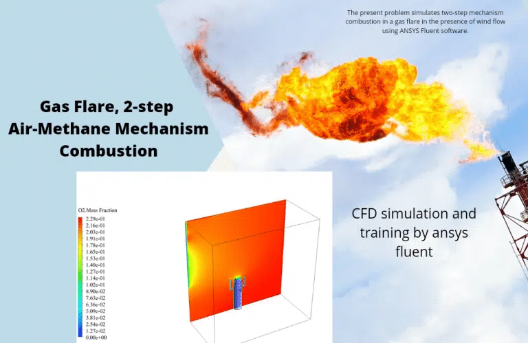
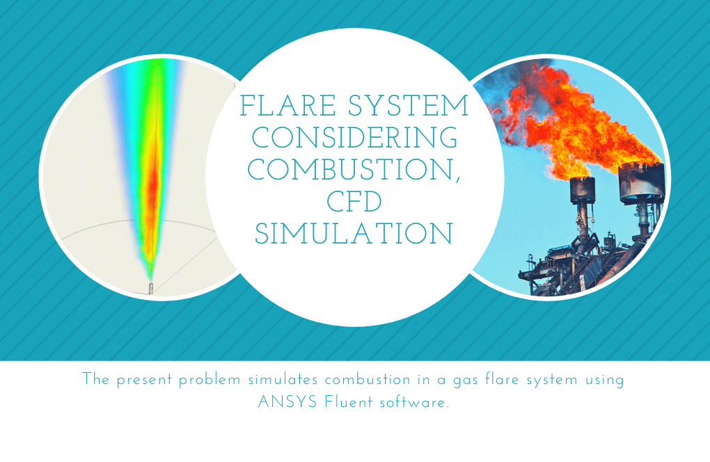
Gas Flare, 2-step Air-Methane Mechanism Combustion
This article will teach you how to use ANSYS Fluent to model a two-step air-methane combustion process in a gas flare. The following topics will be covered throughout the tutorial:
- Setting up the simulation environment
- Defining the geometry and boundary conditions
- Setting up the material properties
- Setting up the combustion model
- Running the simulation
- Post-processing the results
Setting up the simulation environment: The first step in configuring the simulation environment is to launch ANSYS Fluent and create a new project. After creating the project, the following step is to construct a new computational domain. This is accomplished by selecting “Create Domain” from the “Mesh” menu. The domain should be configured with the proper proportions for the gas flare.
Establishing the geometry and boundary conditions: The next stage is to specify the simulation’s geometry and boundary conditions. This is done by selecting “Define Geometry” from the “Mesh” menu. The geometry should be configured with the correct dimensions for the gas flare. The boundary requirements must also represent the physical circumstances of the gas flare.
Setting up the material properties: The next step is to configure the simulation’s material properties. This is done by selecting “Define Materials” from the “Mesh” menu. Material attributes should be configured to represent the physical characteristics of the gas flare.
Configuring the combustion model: The next step is to configure the combustion model for the simulation. This is done by selecting “Define Models” from the “Mesh” menu. The combustion model should be configured to represent the two-step air-methane combustion process.
Running the simulation: The simulation will be executed next. This is accomplished by selecting “Run Simulation” from the “Mesh” menu. Run the simulation until the required results are reached.
Post-processing the simulation results: The final stage is to post-process the simulation results. This is accomplished by selecting “Post-Process Results” from the “Mesh” menu. Post-processing should be carried out in order to interpret and visualise the simulation findings.
Well Drilling, Mud and Sand Separator
ANSYS Fluent software is used to simulate well drilling and sludge separation in this case. A cylindrical hole is modeled as a well in this simulation, with a spinning body in the shape of a cylinder put within. A Non-Newtonian substance for drilling operations flows within the cavity, mixing the mud particles inside. This revolving cylindrical body, with its rotational motion of 100 rpm, may separate and lift the mud particles intermingled in the non-Newtonian fluid. As a result, the flow in the well has been defined using the Eulerian multiphase model. The primary phase of this multiphase flow is connected to the same non-Newtonian fluid known as CMC, while the second phase is related to drilling mud particles.
In circumstances when there is a concentration of more than 10% of dispersed particles in the base fluid, pneumatic transitions for liquid and solid flows, the slurry flows in a liquid and solid, deposition as two-phase liquid and solid flows, and so on, the Eulerian multiphase model is utilized. In this simulation, the volume proportion of the base fluid within the computational region is 0.87, and the volume % of the mud solution particles is 0.13. In terms of viscosity, fluids are classified into Newtonian and non-Newtonian fluids. The viscosity of a fluid is a parameter that represents the fluid’s resistance to flow. Newtonian fluids adhere to Newton’s viscosity law (shear stress in a Newtonian fluid changes linearly with strain rate).
Gas and Petrochemical Industrial Companies
- ExxonMobil
- Chevron Corporation
- Royal Dutch Shell
- BP
- Total SA
- PetroChina
- Sinopec
- Valero Energy Corporation
- Marathon Petroleum Corporation
- Phillips 66
MR CFD Industrial Experience in the Gas and Petrochemical Field
Following are some examples of Gas and Petrochemical industrial projects that are recently simulated and analyzed by MR CFD in cooperation with related companies.
CFD usage for Venturi Scrubber
- The performance of an industrial 720-2 series venturi scrubber is quantitatively examined in this research using ANSYS Fluent
- Sand particle removal research
- The two-way Discrete Phase Model (DPM) and the VOF multiphase model were used
- Transient is used for the simulation
Venturi scrubbers are air pollution control device that reduces particulate particles in the air. They’re often utilized in industrial settings to cut pollutants from activities including combustion, grinding, and material handling. Venturi scrubbers have been subjected to numerical analyses in order to better understand their performance and enhance their design. These studies often employ computational fluid dynamics (CFD) to simulate the flow of air through the scrubber and anticipate the device’s removal effectiveness. The findings of these studies may be utilized to establish the best design parameters for a specific application, such as scrubber size and shape, media type, and operation circumstances.
Venturi scrubbers’ industrial uses include the removal of dust and other particulate matter from industrial exhaust streams. They are also used to minimize the quantity of VOCs in the air, as well as the amount of sulfur dioxide and other pollutants emitted by power plants. Venturi scrubbers are also used to minimize the number of airborne pollutants in the food and beverage sector.
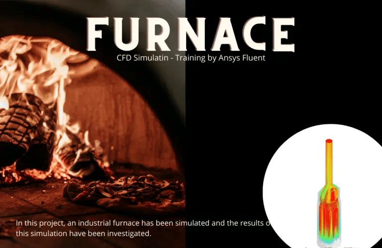
Furnace, Numerical Study, Industrial Application
- ANSYS Fluent software is used to numerically simulate the Furnace in this case.
- Using the Design Modeler, we created the 3-D model.
- The model is meshed using ANSYS Meshing software, and the element number is 7800000.
- The combustion process between methane and air is defined using the Species Transport model.
An industrial furnace was simulated in this research, and the simulation results were analyzed using ANSYS Fluent software. This CFD project is carried out and investigated using CFD analysis. Ansys Fluent software was used to numerically simulate an industrial furnace in this project. The furnace replicated in this project uses methane fuel to heat the methane in the pipes, allowing it to be transported more quickly and with less force.
The results show that the exit temperature of methane pipes has risen in comparison to the intake temperature. The fuel enters the furnace and mixes with the air, causing combustion to occur. Six burners are mounted on the furnace’s floor. The flame strikes the pipes inside the furnace’s radiant portion, heating the liquid inside the pipe, Methane. As burned gases, combustion gases are expelled from the chimney.
The geometry of the current work was created using SolidWorks software (drawing pipes) and the remainder of the geometry was created using Design Modeler software, which has the same dimensions as the model in the attached catalog. Furnaces are used in the oil, gas, and petrochemical sectors to produce heat for numerous operations that need temperatures above 400 degrees Celsius.
To transfer heavy mineral flood oil, it is frequently essential to lower the viscosity by heating the oil in the furnace. This project’s goal is to raise the temperature of methane. In this project, the ANSYS Fluent software was used to numerically excite an industrial furnace. The furnace replicated in this project uses methane fuel to heat the methane in the pipes, allowing it to be transported more quickly and with less force. The results show that the exit temperature of methane pipes has risen in comparison to the intake temperature.
Introduction to Furnace Industrial Application: Oil is one of nature’s most precious gifts to humanity. The significance of oil in humanity’s economic, political, and social realms cannot be overstated. Oil, as a fundamental component, has aided economic progress, employment, and peace.
As a result, one of the key issues in the oil sector is the displacement of it or its products in transmission lines, which is difficult to move owing to high viscosity. As a result of the reduced viscosity, heating the required fluid improves displacement in the tube. Furnaces, like other pieces of equipment, evolve with time, and as technical knowledge advances, their efficiency, and safety improvements with new designs. Engineers’ conceptual preoccupations in developing and producing various types of furnaces include increasing efficiency as much as feasible, enhancing safety, simplicity, guidance, and the flexibility to employ diverse fuels in the furnaces.
How the Device Works: The fuel enters the furnace and mixes with the air, causing combustion. Six burners are mounted on the furnace’s floor. The flame strikes the pipes inside the furnace’s radiant portion, heating the liquid inside the pipe, Methane. As burned gases, combustion gases are expelled from the chimney.
Shell and Tube Heat Exchanger Numerical Study, Industrial Application
Shell and tube heat exchangers are commonly employed in industrial applications to transfer heat from one fluid to another efficiently. CFD simulations may be used to investigate and optimize the performance of these heat exchangers.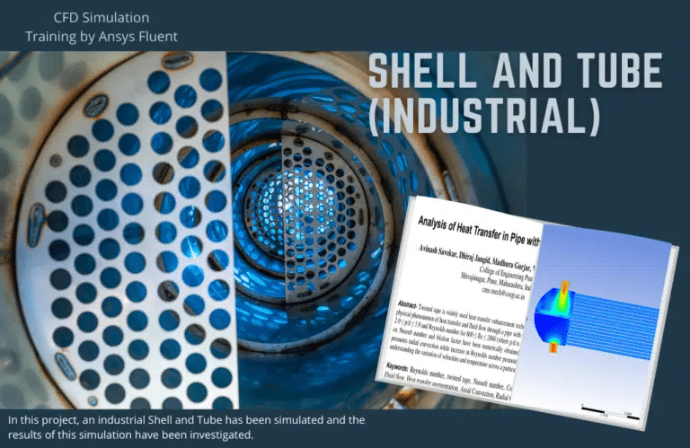
The goal of this research is to lower the temperature of the oil. A shell and tube heat exchanger is a kind of heat exchanger. It is the most often used form of heat exchanger in oil refineries and other big chemical processes, and it is best suited for high-pressure applications. This form of the heat exchanger, as the name indicates, is made up of a shell (a big tank) with a bundle of tubes inside it. To transfer heat between the two fluids, one fluid flows through the tubes and another fluid flows over the tubes (via the shell). Ansys Fluent software was used to excite an industrial shell and tube in this project. After modeling the existing shell and tube, it was discovered that this heat exchanger had the requisite efficiency in refineries.
Assume that in another case study, the needed temperature is substantially lower than the obtained value. Various shells and tubes can be employed by adjusting the tube’s output temperature and taking into account varied configurations and operating circumstances.
MR CFD conducted numerous outsourced CFD simulation projects for industrial companies and research in Gas and Petrochemical Engineering applications. With several years of experience simulating various problems in various CFD fields using ANSYS Fluent software, the MR-CFD team is ready to offer extensive services of CFD Simulation, Training, and Consultation.
You may find the learning products in the Gas and Petrochemical Engineering CFD simulation category in Training Shop. You can also benefit from Gas and Petrochemical Engineering training packages appropriate for Beginner, Intermediate, and Advanced users of ANSYS Fluent. Also, MR CFD is presenting the most comprehensive Gas and Petrochemical Engineering Training Course for all ANSYS Fluent users from Beginner to Experts.
Our services are not limited to the mentioned subjects, and the MR CFD is ready to undertake different and challenging projects in the Gas and Petrochemical Engineering modeling field ordered by our customers. We even carry out CFD simulations for any abstract or concept design you have in your mind to turn them into reality and even help you reach the best design for what you may have imagined. You can benefit from MR CFD expert Consultation for free and then Outsource your Industrial and Academic CFD project to be simulated and trained.
By outsourcing your project to MR CFD as a CFD simulation consultant, you will not only receive the related project’s resource files (Geometry, Mesh, Case & Data, …), but also you will be provided with an extensive tutorial video demonstrating how you can create the geometry, mesh, and define the needed settings(pre-processing, processing, and post-processing) in the ANSYS Fluent software. Additionally, post-technical support is available to clarify issues and ambiguities.
