Project Outsourcing
Outsource your project to the MR CFD simulation engineering team. Our experts are ready to carry out every CFD project in all related engineering fields. Our services include industrial and academic purposes, considering the ANSYS Fluent software's wide range of CFD simulations. By outsourcing your project, you can benefit from MR CFD's primary services, including Consultation, Training, and CFD Simulation. The project freelancing procedure is as follows:
An official contract will be set based on your project description and details.
As we start your project, you will have access to our Portal to track its progress.
You will receive the project's resource files after you confirm the final report.
Finally, you will receive a comprehensive training video and technical support.
What is the Radial Basis Function (RBF) Morph / Mesh Morphing?
Mesh morphing involves adapting a computational grid for computer-aided engineering (CAE). For instance, the solid or shell mesh of a structural part ready to be processed by an FEA solver, or the volume mesh complete with boundary conditions for a CFD solver, can take a new shape by just updating nodal positions. This means that the mesh’s topology (node count, cell count, connectivity) stays the same. Only the nodes’ x,y, and z coordinates in the part of the model undergoing a shape modification are updated. Mesh morphing can be used for different purposes: create shape parameters (i.e., change a length, an angle, a thickness), move onto a new known shape (i.e., as manufactured, as designed by CAD), move onto a body predicted by the CAE solution (automatic shape optimization with adjoint or BGM), and support multiphysics (move CFD mesh according to the evolution of the FEM-connected one, enable erosion/deposition).
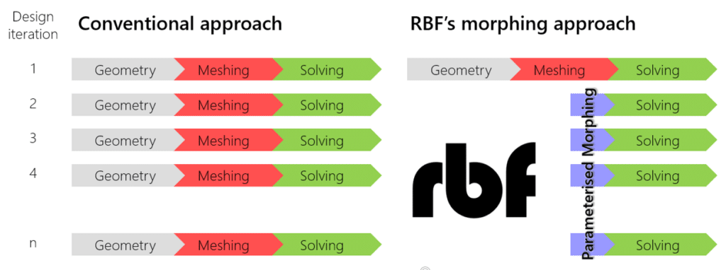
Usually, mesh morphing is faster than remeshing for many reasons: it avoids “meshing noise” (having the same mesh adapted means the effect of a parameter is not confused with the impact of a new mesh structure), so variation effects can be assessed even with a coarser mesh. The CAE model can be updated in the background, keeping all the original settings (boundary conditions). The update of nodal positions usually requires less computational effort vs. a complete mesh regeneration. Creating shape parameters with mesh morphing is faster than creating a parametric CAD model.
RBFs are a mathematical tool capable of interpolating available fields on a cloud of points. Mesh morphing defines a displacement field on a cloud of source points (usually some of the surfaces/curves of the CAE mesh). It then propagates it on a cloud of target points (usually the nodes of the volume/surface mesh of the CAE model undergoing adaption). The method fits very well with mesh morphing needs: its meshless nature allows you to easily manage partitioned meshes used for high-performance parallel computation (HPC); its node-wise nature will enable you to have complete control of specific areas. The computational cost of RBF can be very high, so specific algorithms (Fast Radial Basis Functions) are required to enjoy such benefits for industrial applications.
Reduced-order models (ROM), as suggested by their name, are numerical models of a system (fluid, structure, or other physics) capable of working very fast (typically in real-time). ROM is defined by adopting data-compression algorithms and applying them to many different instances (also known as snapshots) of the original model to be reduced.
RBF and ROM are not intended to improve meshing but rather allow for a link between CAE/meshing and the implementation of real-time Digital Twins. RBF is, in fact, a method of mesh morphing that supports the automatic generation of shape variations of the original mesh. Some distortion of the cells undergoing the deformation (stretching/compression) usually occurs, and a suitable mesh morphing method must preserve the quality of the morphed mesh. RBF is proven to be one of the best solutions nowadays available to implement high-quality mesh morphing: the core of the mesh is adapted with minimum distortion, and the distribution of mesh size close to the surfaces (boundary layers to capture the flow, refinement layers to capture stress raisers) is very well preserved.
Radial Basis Function (RBF) Morphing is a technique that is utilized in computational mechanics, computer graphics, and, most specifically, finite element simulations. It is also known as Mesh Morphing. The deformation of a mesh can be controlled by the application of this mathematical technique by making use of radial basis functions.
The following is an abbreviated explanation of the idea:
The creation of a new mesh from an existing one requires some initial mesh distortion in order to do RBF morphing. A group of control points are responsible for directing the deformation. A real-valued function whose value is determined only by the distance from the origin, a radial basis function is associated with each control point in the network. This function’s value is known as the radial basis value.
Moving the control points produces the new mesh by altering the shape of the related radial basis functions, which in turn alters the shape of the mesh itself. In computer graphics, the RBF morphing approach is used frequently for tasks such as facial animation. In engineering, the technique is utilized for parametric studies in situations in which the shape of a model needs to be updated systematically.
In markdown format, the following is a straightforward representation of the concept:
- Original Mesh
- Control spots
These are certain spots picked on the mesh that will guide the deformation. Control points are also known as control nodes.
- Radial Basis Functions
Each of the control points has a radial basis function that is connected with it.
- Deformed Mesh
When you move the control points, the shape of the radial basis functions shifts, which in turn causes the mesh to take on a new form.
How can RBF Morph CFD simulation be applied in Engineering?
RBF Morph is a tool that extends the capabilities of morphing that are available in ANSYS’s CFD (Computational Fluid Dynamics) simulation software. It is an add-on for ANSYS. It is very helpful in the subject of engineering for a number of reasons, including the following:
– Design Optimization: RBF Morph makes it possible to make rapid alterations to the shape of an object while preserving a high level of accuracy. Because of this, it is a good tool for design optimization, which allows engineers to test a variety of design adjustments and observe the impact these variations have on the performance of the design.
– Parametric Studies: RBF Morph Makes It Easy For Engineers To Set Up Parametric Studies RBF Morph makes it easy for engineers to set up parametric studies. This allows them to investigate the effects that various factors have on the performance of a design, which assists them in better understanding the design space and allows them to make decisions that are based on more accurate information.
– Reduced Computational Expenses: RBF Morph has the potential to dramatically cut down on the amount of money spent on computations. Because it is able to complete simulations at a significantly faster rate than conventional CFD methods, it is an efficient and cost-effective solution for difficult engineering issues.
– Real-Time Simulation: RBF Morph makes it possible to run simulations in real-time. Because of this, engineers are able to interact with the simulation, altering its parameters on the fly while simultaneously observing its effects in real-time. When designing control systems or investigating “what-if” scenarios, this might be an especially helpful tool to have.
An example of a fundamental application of markdown is as follows:
- Within your ANSYS environment, you will need to perform some initial setup for the RBF Morph tool.
- Define your starting point for the design, then proceed to set up your CFD simulation as you typically would.
- In order to adjust the parameters of your design, you must first define them.
- Start the simulation, and then make any necessary adjustments to the design settings in RBF Morph.
- Perform a thorough analysis of the findings, then make any necessary adjustments to your plan.
Keep in mind that the implementation of RBF Morph can look very different depending on the technical domain in question and the individual challenge being tackled. When deciding how to use this tool, you should always keep the requirements of your project in mind.
MR CFD services in the Mesh Morphing Simulation for Engineering and Industries
With several years of experience simulating various problems in various CFD fields using ANSYS Fluent software, the MR CFD team is ready to offer extensive modeling, meshing, and simulation services. Simulation Services for RBF Morph CFD simulations are categorized as follows:
- Optimization of different structures
- Parametric investigation of various factors affecting a system
- …
MR CFD services in the Mesh Morphing Simulation for Engineering and Industries encompass a variety of simulation services that are intended to provide comprehensive, accurate, and time-effective solutions for a wide variety of difficulties that are encountered in the engineering and industrial sectors.
The following are some of the most important services:
– Mesh Morphing: Mesh Morphing is the process of altering the mesh to reflect changes in the geometry of the model without having to regenerate the entire mesh. This is accomplished through the use of a morphing tool. This comes in especially handy in simulations when the geometry shifts over time or as a direct effect of the simulation itself.
– Computational Fluid Dynamics (CFD) Simulations: MR CFD offers an extensive selection of CFD simulation services, such as flow, turbulence, heat transfer, and reactive flow simulations. These services are categorized under the umbrella term “computational fluid dynamics” (CFD). The behavior of fluids in a variety of technical and industrial settings can be analyzed using these models, which can provide useful insights into that behavior.
– Structural Analysis: This service involves the use of simulations to examine the structural integrity of a variety of different design iterations. This can assist in discovering potential vulnerabilities as well as areas in the design that could use some refinement.
– Thermal Analysis: This entails running simulations in order to evaluate the thermal behavior of a number of different designs. This can assist in identifying potential problems that are associated with heat transmission and thermal stress.
– Multiphysics Simulations: This service involves the use of simulations that incorporate several physical phenomena into a single model, such as the flow of fluids, the transmission of heat, and the behavior of structures. This can provide a more in-depth insight into how a design operates when subjected to a variety of different conditions.
– Consulting Services: MR CFD also offers consulting services to help clients understand the results of their simulations and how to apply those insights to enhance the designs and processes they use in their businesses. MR CFD’s consulting services can be found here.
RBF Morph in ANSYS Fluent
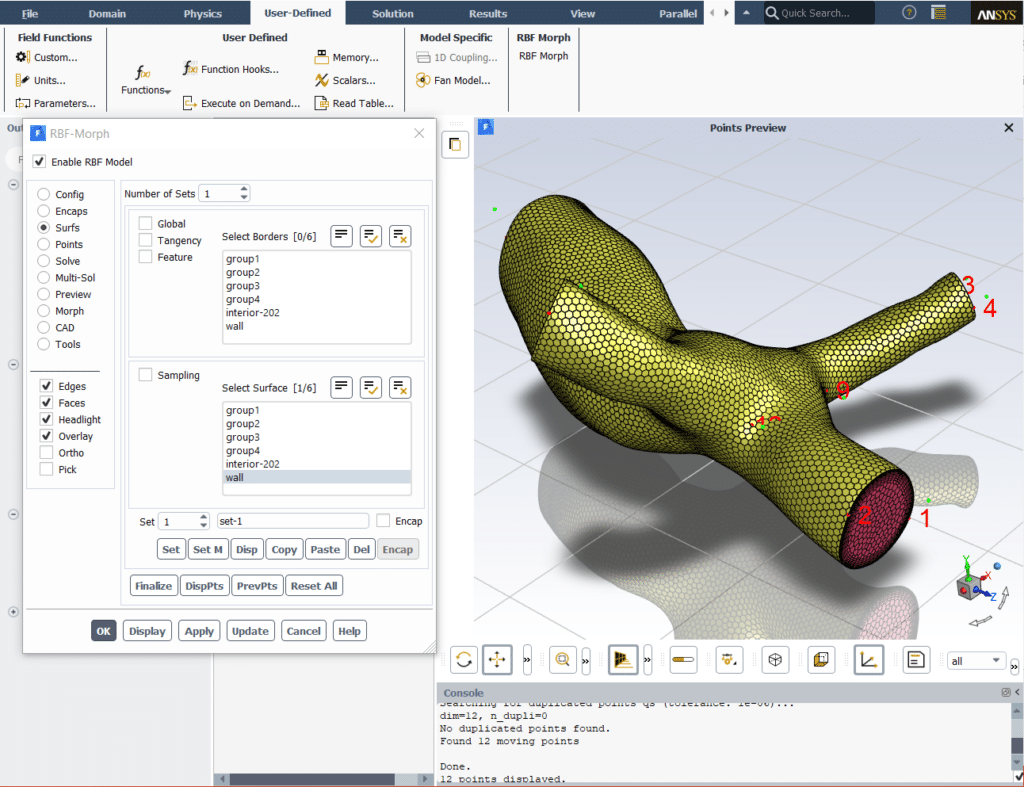
The add-on version of RBF Morph allows for shape optimization studies entirely within ANSYS Fluent by morphing an existing mesh. The main features of the RBF Mesh Morph add-in include:
User Interface: dedicated GUI and TUI.
Mesh Topology: Modifying the original surface and volume mesh produces nodal smoothing without changing the mesh topology.
Surface Morphing: surface meshes can be modified by free surface deformation, rigid movement, or scaling.
Volume Smoothing: high-quality smoothing of the volume mesh with relatively large movements possible in a single-step deformation.
Versatility: nodal smoothing is achieved using a meshless approach independent from the mesh structure, handling every kind of mesh element type (tetrahedral, hexahedral, polyhedral, prismatic, hex-core, non-conformal interfaces, etc.).
Reusability: the RBF solution can be applied to any mesh representing the same geometry.
Consistency: mesh characteristics are preserved, so mesh consistency is ensured (element size, type, distribution, prism layers, etc.).
Parallelism: parallel calculation for large models (many millions of cells).
Efficiency: flow solutions are fully readable through all the morphed mesh, reducing the number of iterations to converge.
Precision: exact movement is ensured for the moving nodes’ locations and exact feature preservation.
Parameterization: multi-parameter and multi-step problems.
RBF Morph is an add-on for ANSYS Fluent that offers an approach for morphing meshes that is both powerful and efficient. This method is founded on the Radial Basis Functions (RBF) interpolation. It makes the process of optimizing the design and setting up the parametric settings in a way that is clear and user-friendly.
The following is an introduction to the RBF Morph function found in ANSYS Fluent:
– Install RBF Morph: Make Sure RBF Morph Is Correctly Installed. The first thing you need to do is check to see if the RBF Morph add-on was installed properly. On the official website for RBF Morph, you’ll find a guide that will walk you through the installation process.
– Launch ANSYS Fluent: Begin by starting ANSYS Fluent and then loading your project.
– Activate RBF Morph: To activate RBF Morph, navigate to the Define menu, then click User-Defined, then Functions, and finally Compiled. To load the RBF Morph library file, choose it after clicking the ‘Load’ button and looking for a file named librbfmorphudf.
– Configure RBF Morph: At this point, you are able to configure RBF Morph in accordance with your needs. This may be accomplished by going to Define > Models > RBF Morph. In this section, you will be able to select parameters such as control points, morphing mechanisms, and so on.
– Start the Simulation: When you have finished configuring the settings, you can start the simulation. The morphing of the mesh will take place in accordance with the settings that you have selected in RBF Morph.
Please keep in mind that the information presented here is quite basic. Your unique project and its requirements will determine the specific stages and parameters that need to be followed.
Mesh Morphing MR CFD Projects
The following is a list of possible subject areas for a Mesh Morphing MR CFD Project.
– Morphing of the RBF Mesh Used in Aerodynamics
Research should be done on how RBF mesh morphing can be applied in the field of aerodynamics. For this purpose, RBF mesh morphing might be used to model the aerodynamics of a variety of various shapes and structures.

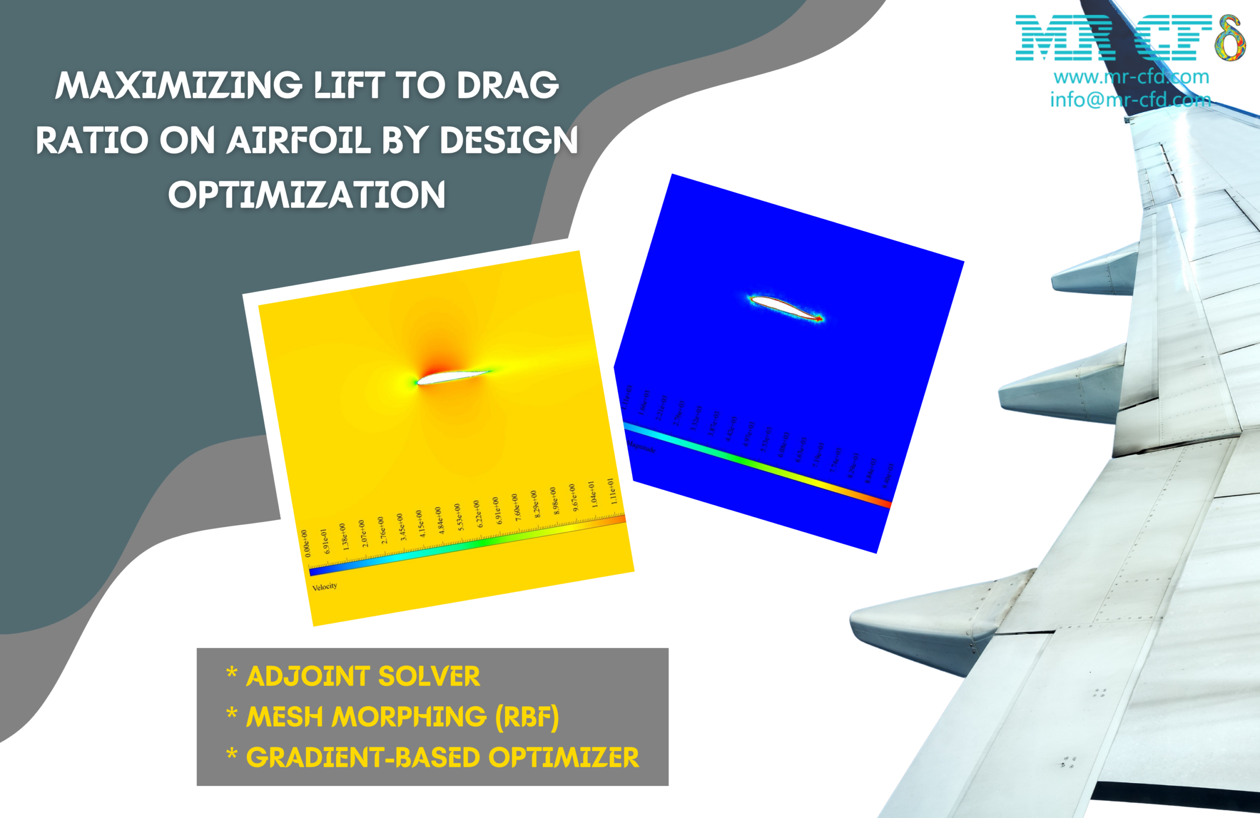
The Ansys Fluent program was used to do the initial simulation in this research, which modeled the flow that occurs within a NACA0012 airfoil. The angle of attack is 1.53 degrees, and the simulation was carried out via a density-based solver because the compressibility required it. The simulation was run at a Mach number of 0.7. After that, the geometry is worked on to improve the lift-to-drag ratio (also known as L/D), which is a measure of aerodynamic efficiency. The Ansys Fluent program operating within the Ansys Workbench environment was responsible for performing all of the optimizations. The step of optimization consists of three distinct stages of execution. Only the movement of points in the vertical direction was taken into account in the first step, and the best answers were found for the maximum lift-to-drag ratio and the maximum lift coefficient. The lift-to-drag ratio was calculated for two new modes after each of these two ideal solutions was considered for horizontal displacement in the subsequent phase. Following optimization, we were successful in locating the spots that provided the greatest possible lift-to-drag ratio.
Maximizing Lift to Drag Ratio by Adjoint Solver (RBF), ANSYS Fluent CFD Simulation Tutorial
This research is concerned with the application of the Ansys Fluent software to a numerical simulation of the Lift to Drag Ratio on an Airfoil. We plan to use an adjoint solver and a gradient-based optimizer in order to make this model’s design as efficient as possible.
When it comes to aerodynamics, one of the most frequent topics of discussion for engineers and designers is the investigation of the performance of airfoils. When it comes to aerodynamic performance, having an optimal design is of the utmost importance. Both lift and drag are essential forces that contribute to aerodynamics. The force of drag is exerted in the same direction as the flow, while the force of lift acts in the opposite direction of the flow.
Because the drag force acts in the opposite direction of the movement of the airfoil, it slows down the movement of the airfoil. Because the lift force acts in an upward direction, it is a contributing factor that helps in the process of overcoming the weight force. Therefore, to increase the performance of the airfoil, it is necessary to decrease the amount of drag while simultaneously increasing the force of lift. As a consequence of this, our objective in this challenge is to maximize the lift-to-drag ratio.
The simulation is carried out in three distinct steps. To begin, we will run the simulation using the normal flow. In the second phase, we make use of the adjoint solver to perform an analysis of the Sensitivity. In the final step, we alter the design of the model in order to attain optimal performance using the gradient-based optimizer.
A sequence of data that is expressed in the form of sensitivity analysis is provided by the adjoint solver. Our primary concern is shape sensitivity. This tool determines which aspects of the geometry have the most significant impact on the overall performance of the system.
Therefore, we must establish a target parameter. Observable is the name given to this output parameter. We are required to make use of something called an Operation in order to define a combination of observables. In the work that we have done so far, the lift-to-drag ratio has been operationally established.
The lift-to-drag ratio that is applied to the airfoil is the foundation for the adjoint solver. It has a bigger impact on the lift-to-drag ratio anywhere there is a greater display of Sensitivity, such as when there is displacement of the border or deformation of the shape of the design.
In the gradient-based optimizer, we make use of the results from the sensitivity analysis. Using this tool, we may specify the changes that should be made to the operation. For instance, one of the things that we are looking into for this project is increasing the lift-to-drag ratio. Changing the geometry of the airfoil in order to maximize the ratio is necessary. The result of these modifications should be an improved design.
As was said earlier, the current simulation is carried out in a series of three successive steps. As a result, we proceeded to evaluate the results in three stages. We were able to get velocity and pressure contours by the use of standard flow modeling. These contours illustrated the various distributions of velocity and pressure that existed throughout the domain. In the adjoint solution, we analyzed the Sensitivity. We were able to determine the contour of the form sensitivity around the airfoil.
The leading edge of the airfoil has the least Sensitivity, while the trailing edge has the most. This indicates that the amount of lift to drag ratio is most sensitive to changes in boundary displacement and shape deformation in these particular regions of the aircraft. Therefore, if we want to enhance the ratio, we need to concentrate on the trailing edge of the airfoil. The gradient-based optimizer’s ultimate solution involves the geometry going through some deformation.
Minimizing Drag Force by Adjoint Solver (RBF), ANSYS Fluent CFD Simulation Training
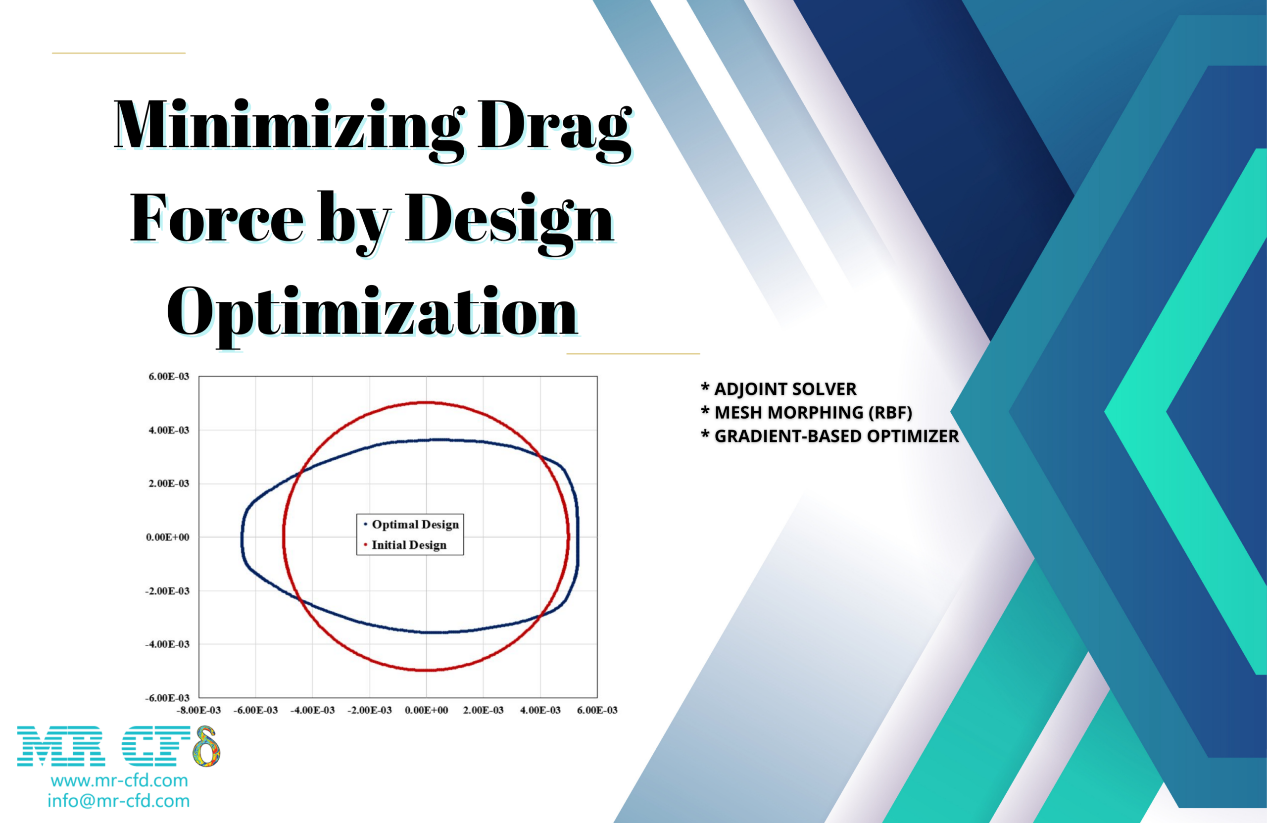
This project is about utilizing the program Ansys Fluent to perform a numerical simulation of the drag force that is exerted on a straightforward cylindrical obstruction. We plan to use an adjoint solver and a gradient-based optimizer in order to make this model’s design as efficient as possible.

A sequence of data that is expressed in the form of sensitivity analysis is provided by the adjoint solver. Our primary concern is shape sensitivity. This tool determines which aspects of the geometry have the most significant impact on the overall performance of the system. Therefore, we must establish a target parameter. Observable is the name given to this output parameter. We have characterized the drag force as observed in the study that we are presenting here.
As a result, the adjoint solver is formulated on the basis of the drag force that is exerted on the cylinder. It has a bigger impact on the drag force wherever there is a greater display of Sensitivity, which can be interpreted as a displacement of the border or a deformation of the shape of the design.
In the gradient-based optimizer, we make use of the results from the sensitivity analysis. With the help of this tool, we may specify the manner in which the observable should be altered. For instance, one of the goals that we have for this project is to reduce the amount of drag force. This necessitates a modification to the design of the cylinder in order to reduce the amount of drag. The result of these modifications should be an improved design.
As was said earlier, the current simulation is carried out in a series of three successive steps. As a result, we proceeded to evaluate the results in three stages. We were able to get velocity and pressure contours by the use of standard flow modeling. These contours illustrated the various distributions of velocity and pressure that existed throughout the domain.
The pressure contour reveals that the area in front of the cylinder, which is situated so that it is immediately in the route that the water takes, has the maximum pressure. The velocity contour also reveals a wake that is produced by fluid separation and is located behind the cylinder. In the adjoint solution, we analyzed the Sensitivity. We were able to determine the contour of the shape sensitivity around the cylinder.
The cylinder’s upper and lower halves, specifically, display the greatest levels of Sensitivity. This indicates that the quantity of drag force is most sensitive to changes in shape and boundary displacement in these regions of the body. Therefore, in order to lessen the amount of force exerted by the drag, we need to concentrate on the upper and lower regions of the geometry. The gradient-based optimizer’s ultimate solution involves the geometry going through some deformation.
– The Optimization of Turbomachinery Through the Implementation of RBF Mesh Morphing
Conduct research into the potential applications of RBF mesh morphing for improving the efficiency of turbomachinery. It may be possible to achieve this goal by simulating and then optimizing the flow of fluid through a turbine by employing RBF mesh morphing.
– RBF Mesh Morphing for Applications in Biomedical Engineering
Investigate the possibility of applying RBF mesh morphing in the field of biomedical engineering. The simulation of the flow of blood through the cardiovascular system might be accomplished by the use of RBF mesh morphing in this case.
– Fluid-Structure Interaction (FSI) in Combination with RBF Mesh Morphing
Investigate the usage of RBF mesh morphing to model fluid-structure interactions and see how it may be done. To accomplish this goal, you might use RBF mesh morphing to model the effect of fluid flow on a structure and the subsequent deformation of the structure.
– The Evolution of RBF Mesh Due to Heat Transfer
Research how heat transfer models can benefit from using RBF mesh morphing. As part of this process, you might use RBF mesh morphing to replicate the way heat is transferred through a variety of materials and structures.
– Improvements in Vehicle Performance Made Possible Thanks to RBF Mesh Morphing
Investigate the possibility of using RBF mesh morphing to improve the overall performance of vehicles. This could involve using RBF mesh morphing to mimic and perfect the vehicle’s aerodynamics in order to achieve the desired result.
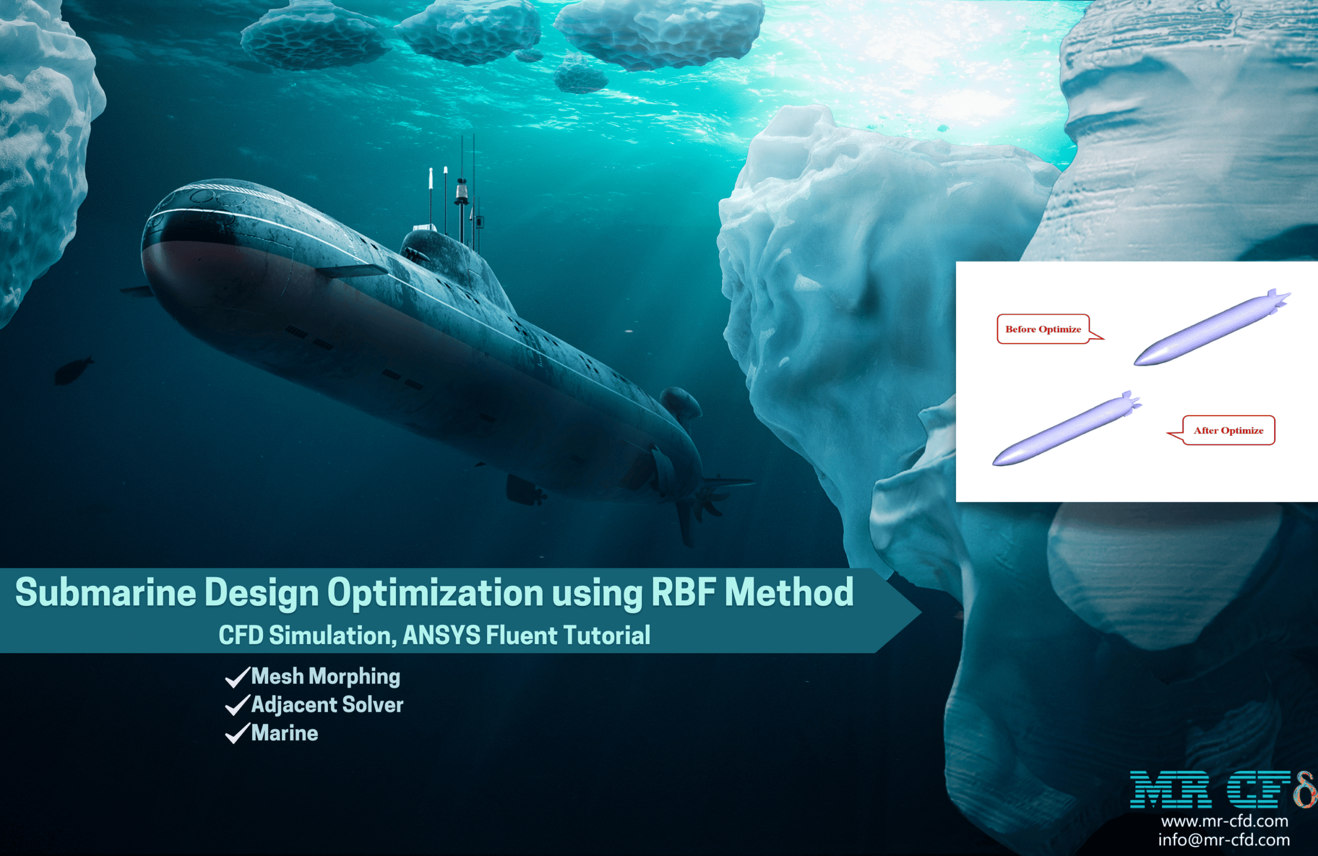
Submarine Design Optimization using RBF Method CFD Simulation, ANSYS Fluent Tutorial
Through the use of the adjoint solver provided by the ANSYS Fluent software, the purpose of this simulation is to optimize the design of a submarine. The body of a structure is subject to forces from the fluid whenever the structure is moving at a particular speed inside a fluid that is continuous. For instance, the body of a submarine will experience forces exerted by the surrounding water as the submarine moves through the sea. The drag force is one of the important forces that has been explored.
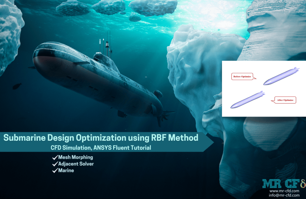
During the optimization phase, a CFD analysis of the drag force that is applied to the submarine is carried out in order to produce an adequate geometry. There are numerous different approaches to improving the body’s design through optimization. In order to do geometric optimization, the ANSYS Fluent program makes use of an adjoint solver tool. By carrying out a solution procedure, this tool is able to bring about modifications in the dimensions of the geometry that is being targeted. These alterations will continue until a geometry with the desired properties is achieved.
In order to lessen the effect of the drag force, this simulation makes use of an optimization procedure that is based on an adjoint solver. The adjoint solver tool is used to do the optimization process, which is done in three parts. To begin, the simulation was run in standard mode within the Ansys Fluent software using a fundamental geometry for a submarine as the starting point.
In this mode, the calculation of the drag force takes place. The adjoint solution is employed in the second stage, which involves identifying a target parameter, which in this case is the drag force. Using the adjoint solution, one may determine which regions of the undersea geometry are most sensitive to the total amount of drag force.
It is now possible, as a result of this work, to determine which geometrical modifications in which regions of the geometry contribute to geometrical optimization. In the third stage, the process of optimization has been completed based on a set percentage, with the goal of lowering the objective parameter (drag force).
The investigation into the drag force was carried out once the simulation had been completed. During the preliminary stages of the modeling process, the drag force was estimated to be 11.485855 N. The adjoint solver was utilized to execute an optimization operation, and the final result was that the drag force was equal to 6.4377518 N. This results in a 44% decrease in the amount of force exerted by the drag. Therefore, it is safe to say that the model’s optimization was carried out appropriately.
The modification of the model’s geometry allowed for the achievement of this decrease in the amount of drag force. As a consequence of this, adjustments were made to the model’s dimensions. Checking the range of modifications both before and after optimization has been done with the use of the program called iso-clip.
Both the cross-section and the side-section dimensions have been looked into for their dimensional shifts. The dimensions of the cross-section have been altered to now read 0.4386431*0.453043, down from the previous value of 0.5066175*0.5063399. The dimensions of the side section are now 4.09195906 and 0.5952543, down from their previous value of 4.353052 and 0.6.
Because the drag force is proportional to the cross-sectional area, decreasing the cross-sectional area results in a reduction in the amount of force exerted by the drag. The findings of this simulation provide further evidence that this problem exists. In addition, the total pressure and frictional forces that contribute to the drag are added together to arrive at the total drag force.
The divergence in water pressure that exists between the two sides of the submarine is what causes the phenomenon known as pressure drag. Therefore, the pressure difference will be reduced in proportion to the submarine’s decreased cross-sectional area. The surface of the submarine’s sides also affects the amount of frictional drag. Therefore, the drag force will be reduced the more the side surface of the submarine is submerged.
Minimizing Pressure Drop by Adjoint Solver (RBF), ANSYS Fluent CFD Simulation Training
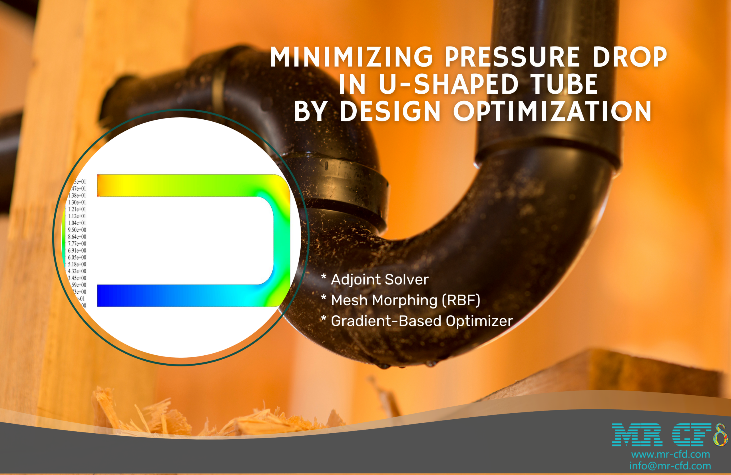
This project involves the use of the program Ansys Fluent to perform a numerical simulation of the pressure drop that occurs in a tube that has a U-shaped bend in it. We plan to use an adjoint solver and a gradient-based optimizer in order to make this model’s design as efficient as possible.
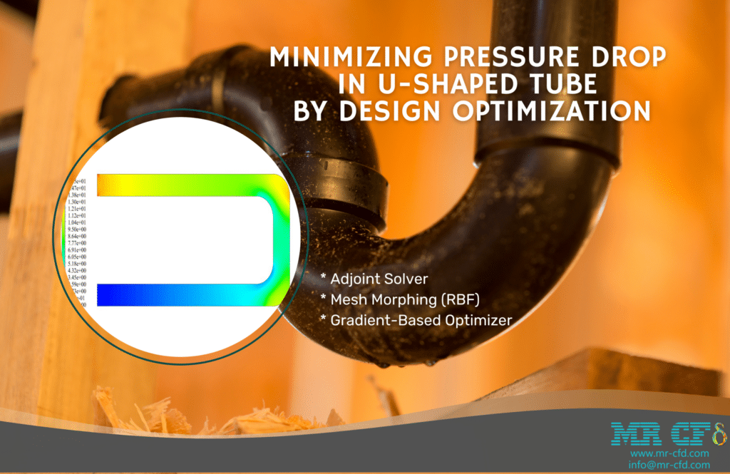
A sequence of data that is expressed in the form of sensitivity analysis is provided by the adjoint solver. Our primary concern is shape sensitivity. This tool determines which aspects of the geometry have the most significant impact on the overall performance of the system. Therefore, we must establish a target parameter. Observable is the name given to this output parameter. In the work that we are presenting here, the pressure drop has been defined as observable.
Therefore, the pressure drop in the tube serves as the foundation for the adjoint solution. It has a bigger impact on the pressure drop wherever there is a greater display of Sensitivity, whether that be a displacement of the border or a deformation of the shape of the design.
In the gradient-based optimizer, we make use of the results from the sensitivity analysis. With the help of this tool, we may specify the manner in which the observable should be altered. For instance, one of the goals that we have for this project is to reduce the pressure drop. This entails making adjustments to the pipe shape in order to reduce the pressure drop. The result of these modifications should be an improved design.
As was said earlier, the current simulation is carried out in a series of three successive steps. As a result, we proceeded to evaluate the results in three stages. We were able to get velocity and pressure contours by the use of standard flow modeling. These contours illustrated the various distributions of velocity and pressure that existed throughout the domain.
The pressure contour demonstrates that there is a decrease in pressure experienced by the fluid flow after it has traveled through the pipe bend. In the adjoint solution, we analyzed the Sensitivity. Inside the tube, we were able to determine the form sensitivity contour.
The area close to the pipe bend demonstrates the greatest level of Sensitivity. This indicates that the value of pressure drop is more sensitive to changes in boundary displacement and shape deformation in these regions of the system. Therefore, in order to lessen the pressure loss, we need to concentrate on the geometry of the bend. The gradient-based optimizer’s ultimate solution involves the geometry going through some deformation.
Elbow Optimization with RBF Morph, CFD Simulation Ansys Fluent Training
The approaches of geometry optimization have seen a significant amount of development in recent years, which has led to improved performance in mechanical devices. Mesh morphing, often known as RBF, is one of these approaches. In the process of mesh morphing, the surface of the lattice can be reshaped while the topology remains unchanged. This technique first establishes a displacement field on a cluster of origin points, and then it propagates that field onto a cluster of destination points.
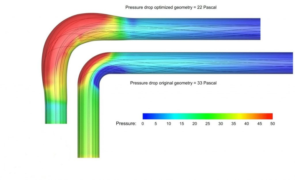
The Ansys Fluent software is used initially in this project to perform a simulation of the flow that occurs within an elbow. Following that, the geometry is adjusted utilizing the morphing mesh optimization approach in order to achieve fewer pressure drops.
When there is a difference in the pressure at two different sites in the fluid carrier network, a pressure drop will result. Pressure drop or pressure loss will take place whenever a liquid substance enters one end of a piping system and exits the other. This happens when the liquid material travels from one end of the system to the other. The pressure drop that occurs across a segment of pipe, a valve, or an elbow is magnified when the flow velocity is high, and the viscosity of the fluid is high. When the velocity is low, the pressure drop will be little or nonexistent.
In this simulation, the pressure contour demonstrates that as the elbow bend is made longer, the regions on the geometry’s periphery see a greater increase in pressure. Additionally, as a consequence of the effect of this elongation, the interior regions of the curve are subject to a greater amount of pressure. On the other hand, it appears from the velocity contour that the velocity in the bending zones has, on the whole, slowed down. As a result, one may conclude that the pressure drop has been reduced as a direct result of improving the geometry, which was made abundantly evident by the value of the optimization diagram.
RBF Morph Application in Industrial Companies
Because of its capacity to execute shape optimization in a manner that is both highly efficient and versatile, RBF Morph is an effective piece of technology that has found widespread application across a variety of business sectors. The following is a list of some of its applications:
– Automotive Industry: RBF Morph is utilized in the automotive industry for the purpose of optimizing vehicle shapes during the design process. It contributes to the improvement of aerodynamics as well as the lowering of fuel efficiency and noise.
– Energy Industry: RBF Morph is used in the energy industry for the design and optimization of wind turbines, gas turbines, and other types of equipment connected to energy production.
– Marine Industry: RBF Morph is used in the marine industry to optimize the design of ships and submarines to improve hydrodynamics, reduce drag, and boost fuel efficiency. Specifically, RBF Morph is employed in the shipbuilding process.
– Biomedical Industry: RBF Morph is utilized in the planning and development of medical devices and implants, as well as their optimization.
MR CFD Industrial Experience in the Mesh Morphing Field
Some examples of Mesh Morphing industrial projects recently simulated and analyzed by MR CFD in cooperation with related companies are visible on the MR CFD website.
You may find the Learning Products in the RBF Morph CFD simulation category in the Training Shop. You can also benefit from the Mesh Morphing Training Package, which is appropriate for Beginners, Intermediate, and Advanced users of ANSYS Fluent. Also, MR CFD is presenting the most comprehensive RBF Morph Training Course for all ANSYS Fluent users from Beginner to Experts. Get more familiar with RBF Concepts.
Our services are not limited to the mentioned subjects. The MR CFD is ready to undertake different and challenging projects in the Mesh Morphing modeling field ordered by our customers. We even carry out CFD simulations for any abstract or concept Design you have to turn them into reality and even help you reach the best strategy for what you may have imagined. You can benefit from MR CFD expert Consultation for free and then Outsource your Industrial and Academic CFD project to be simulated and trained.
By outsourcing your Project to MR CFD as a CFD simulation consultant, you will not only receive the related Project’s resource files (Geometry, Mesh, Case, and Data, etc.), but you will also be provided with an extensive tutorial video demonstrating how you can create the geometry, mesh, and define the needed settings (preprocessing, processing, and postprocessing) in the ANSYS Fluent software. Additionally, post-technical support is available to clarify issues and ambiguities.
Portfolios
-
Sale
Adjoint Solver (Mesh Morphing) Training Course
Original price was: $440.00.$220.00Current price is: $220.00. Student Discount
