Predicting Ship Hull Resistance: A Guide to High-Fidelity CFD for Marine Engineering
The maritime industry is currently navigating its most significant transformation since the transition from sail to steam. With the International Maritime Organization (IMO) tightening regulations through the Energy Efficiency Design Index (EEDI) and the Carbon Intensity Indicator (CII), shipowners are no longer just looking for seaworthiness—they are hunting for fractional percentage gains in efficiency. In this environment, the hydrodynamic performance of the hull is paramount.
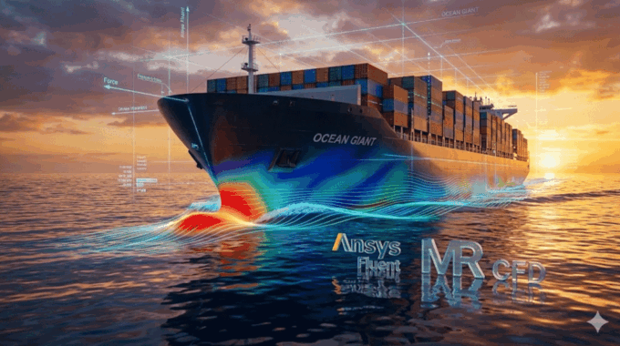
Traditionally, predicting how a hull would behave in open water was the exclusive domain of physical towing tanks. While these facilities remain valuable, they are expensive, time-consuming, and subject to scaling errors. Today, advanced cfd for marine engineering has emerged as the new standard for hydrodynamic analysis. It allows naval architects to virtually “tow” a vessel at full scale, optimizing hull lines, reducing drag, and ensuring compliance before a single sheet of steel is cut.
At MR CFD, we specialize in high-stakes ship hull resistance prediction. We bridge the gap between theoretical hydrodynamics and practical shipyard construction, helping clients navigate the complex physics of fluid-structure interaction. This guide explores the technical methodology behind high-fidelity hull simulation and how it translates to operational profitability.
Why Is CFD Replacing Traditional Towing Tanks in Marine Design?
For over a century, the towing tank was the gold standard. Engineers would build a scale model (typically 3-7 meters long), tow it down a long basin, and measure the resistance. However, this method suffers from a fundamental physics problem known as the “Scale Effect.”
When you scale a ship down, you cannot simultaneously preserve the Froude number (which governs wave making) and the Reynolds number (which governs friction). Towing tanks prioritize Froude similarity, meaning the model operates at a drastically lower Reynolds number (Re≈106) compared to the full-scale ship (Re≈109). Engineers must then use semi-empirical extrapolation methods (like the ITTC resistance procedures) to guess the full-scale friction. This introduces uncertainty.
CFD for marine engineering eliminates this extrapolation entirely.
- Full-Scale Simulation: We simulate the vessel at 1:1 scale, capturing the true boundary layer physics and roughness effects without scaling factors.
- Cost & Speed: A towing tank vs. CFD comparison often reveals that a digital simulation campaign costs a fraction of a physical test and can be iterated upon overnight.
- Detail: A physical model gives you a few data points (drag, trim, sinkage). A CFD simulation gives you millions—pressure at every point on the hull, velocity vectors in the propeller plane, and precise wave profiles.
This shift allows for rapid prototyping. Instead of testing two hull variants in a physical tank, we can test twenty variants in a virtual cluster, ensuring the final design is truly optimized.
What Physics Must We Capture for Accurate Resistance Prediction?

To reduce drag, we must first understand what causes it. In a CFD environment, we don’t just solve for a single “drag force”; we resolve the Navier-Stokes equations to decompose the Total Resistance (RT) into its specific physical components.
According to standard Certified Naval Architecture methods, the total resistance is generally broken down as:
RT=RF+RP
Or, in non-dimensional coefficient form often used in ITTC resistance procedures:
CT=(1+k)CF+CW
Where:
- CT is the Total Resistance Coefficient.
- CF is the Frictional Resistance Coefficient (dependent on Reynolds number and hull roughness).
- CW is the Wave-Making Resistance Coefficient (dependent on Froude number and hull form).
- k is the form factor.
CFD separates these naturally:
- Viscous Pressure Drag & Friction (RF): This arises from the sticky nature of water. As water flows over the hull, shear stresses develop in the boundary layer. CFD calculates this by integrating shear stress over the entire wetted surface area.
- Wave-Making Resistance (RW): As the ship moves, it displaces water, creating a pressure field that manifests as waves (the Kelvin wake). This energy loss is captured by solving the pressure distribution over the hull.
By isolating viscous pressure drag optimization from wave-making resistance analysis, we can make targeted design changes. If RW is high, we modify the bulbous bow to cancel the bow wave. If RF is high, we look at reducing the wetted surface area or applying low-friction coatings.
How Does the Volume of Fluid (VOF) Method Handle the Free Surface?

The most distinct challenge in cfd for marine engineering is the interface between air and water. This is not a single-phase flow; it is a complex multiphase problem where the boundary (the water surface) is constantly moving and deforming.
To solve this, we utilize the Volume of Fluid (VOF) method. In Ansys Fluent, the VOF model introduces a phase fraction variable, α, for each cell in the mesh:
- α=0: The cell contains only air.
- α=1: The cell contains only water.
- 0<α<1: The cell contains the interface (the water surface).
The solver tracks the motion of this interface by solving a transport equation for the volume fraction:
∂t∂α+∇⋅(αv)=0
The challenge lies in preventing the interface from “smearing.” Numerical diffusion can cause the sharp boundary between water and air to become a blurry gradient, which destroys the accuracy of the wave pattern prediction. At MR CFD, we utilize advanced compressive discretization schemes (like Geo-Reconstruct or CICSAM) to keep the interface sharp.
This allows us to visualize the classic Kelvin wake pattern, the height of the bow wave (which indicates energy loss), and the “rooster tail” at the stern. Accurate free surface flow simulation is the only way to predict the ship’s trim (how much the bow rises) and sinkage (how deep the hull settles) at high speeds.
How Do We Configure the Simulation for Maximum Accuracy?
A simulation is only as good as its inputs. In our CFD Consulting Services, we adhere to a rigorous setup protocol to ensure Expertise, Authoritativeness, and Trustworthiness in our results.
What Mesh Strategy Best Captures the Boundary Layer and Wake?
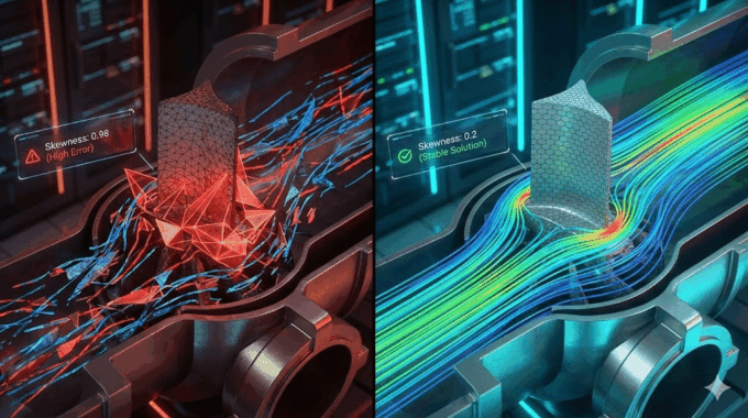
Meshing a ship hull is an art form. You are trying to resolve two competing scales: the massive length of the ship (hundreds of meters) and the microscopic thickness of the boundary layer (millimeters).
- Boundary Layer Resolution: To accurately predict skin friction (RF), we must resolve the viscous sublayer. We use a prism layer (inflation layer) generation strategy to ensure the non-dimensional wall distance, y+, is less than 1 (y+<1). This allows us to use high-fidelity turbulence models like SST k-omega turbulence modeling without relying on wall functions.
- Free Surface Refinement: The VOF method requires a high density of cells at the water level to capture waves. We implement a specific “Kelvin Wedge” refinement zone—a triangular region of fine mesh extending behind the ship to resolve the V-shaped wake pattern.
If the mesh is too coarse at the surface, the waves will artificially “damp out,” leading to an under-prediction of drag.
Dynamic Trim and Sinkage: Should We Use Overset Meshes?
A ship does not move like a brick on a table; it interacts dynamically with the water. As speed increases, the pressure distribution changes, causing the ship to trim (rotate) and sink (vertical translation). Ignoring this can lead to errors of 10-15% in resistance prediction.
There are two primary ways to handle this 2-DOF (Degree of Freedom) motion:
- Deforming/Moving Mesh: The mesh stretches and compresses as the ship moves. This is computationally efficient for small motions but can lead to “negative cell volume” errors if the motion is large.
- Overset (Chimera) Mesh: This is the advanced approach we teach in our Ansys Fluent Training Course. A component mesh (containing the ship) floats on top of a background mesh (the ocean). The meshes overlap, and information is interpolated between them.
For complex dynamic scenarios, such as planing hulls or ships in rough seas, Overset meshing is superior. It allows for large-amplitude motions without degrading cell quality.
How Can CFD Results Improve EEDI and Reduce Fuel Consumption?
The business case for cfd for marine engineering is driven by ROI. The IMO’s EEDI (Energy Efficiency Design Index) requires new ships to meet strict grams-of-CO2-per-ton-mile limits. Failing EEDI compliance means a ship cannot be built.
CFD provides the insight needed to lower the required power (P) in the EEDI equation. By visualizing the static pressure distribution on the hull, we can identify “hot spots”—areas of high pressure that contribute to drag.
Common optimizations include:
- Bulbous Bow Retrofit: We can reshape the bulb to create destructive interference with the bow wave, effectively cancelling it out. We often run parametric studies testing 10+ bulb variations to find the “sweet spot” for the vessel’s operating profile.
- Stern Profile Optimization: smoothing the flow into the propeller to improve the Wake Fraction (w) and Thrust Deduction (t), ensuring the propeller operates in uniform flow.
A drag reduction of just 4% can translate to hundreds of thousands of dollars in annual fuel savings for a large container vessel.
Case Study: How Did MR CFD Optimize a Commercial Vessel Design?
We were approached by a shipyard designing a medium-range tanker. Preliminary towing tank results suggested the resistance was within limits, but the wake field quality was borderline. They feared propeller cavitation—a phenomenon where low pressure causes water to boil on the propeller blades, causing damage and noise.
The Challenge: The stocky hull form was creating a massive separation zone (dead water) ahead of the propeller.
The Solution: Using Full-scale sea trial correlation techniques, we set up a high-fidelity simulation including the propeller using a Virtual Disk model.
- We visualized the nominal wake field and confirmed a severe velocity deficit at the 12 o’clock position.
- We modified the skeg and added Vortex Generators (VGs) upstream of the propeller.
- We re-ran the simulation using the Grid Convergence Index (GCI) verification method to ensure accuracy.
The Result: The CFD analysis showed that the VGs energized the boundary layer, smoothing the inflow to the propeller. Not only was the cavitation risk eliminated, but the improved propulsive efficiency resulted in a 6% reduction in effective power requirement. This direct intervention saved the client potentially millions in retrofit costs and ensured EEDI compliance.
Ready to Optimize Your Hull Performance?
The era of relying solely on empirical charts and expensive physical testing is ending. CFD for marine engineering offers a faster, more accurate, and more cost-effective path to seaworthiness. Whether you are designing a high-speed patrol boat or optimizing a bulk carrier for EEDI, the fluid dynamics data you gather today determines your profitability tomorrow.
At MR CFD, we don’t just run software; we interpret the physics to provide engineering solutions.
- Need a Hull Analysis? Book a discovery call with our naval architecture team.
- Want to Master the Tools? Check out our comprehensive Ansys Fluent Training Course to bring these capabilities in-house.
Frequently Asked Questions
How accurate is CFD compared to physical towing tank tests?
With proper mesh verification and validation against ITTC benchmark data (like the KCS or KVLCC2 hulls), CFD is now typically within 1-3% of towing tank results. In many cases, CFD surpasses towing tanks by eliminating scale-effect errors, as it simulates the vessel at full scale rather than extrapolating from a small model.
What is the benefit of full-scale CFD simulation over model scale?
Testing at full scale eliminates the uncertainty of extrapolating model results (using ITTC friction lines) to the real ship. It captures the true Reynolds number effects on skin friction and the wake field into the propeller. This is critical for predicting propeller-hull interaction accurately, which is often distorted in model-scale tests.
Can CFD simulate ship resistance in rough seas?
Yes. Using unsteady solvers and regular/irregular wave boundary conditions, cfd for marine engineering can predict “added resistance in waves.” We can simulate the ship’s seakeeping behavior (motions like pitch, heave, and roll) to ensure the vessel performs efficiently not just in calm water, but in realistic ocean conditions.
How long does a typical hull resistance simulation take to solve?
It depends on the mesh size and physics complexity, but a standard resistance calculation (single speed) on our High-Performance Computing (HPC) clusters typically completes within 12-24 hours. A full resistance curve (5-7 speed points) can be delivered in 2-3 days, significantly faster than booking and executing a physical tank test.
Does MR CFD offer training for naval architects?
Yes, our Ansys Fluent Courses include specific modules for marine hydrodynamics. We cover the complete workflow: setting up the VOF open channel boundary conditions, configuring 6-DOF motion for trim and sinkage, and analyzing open water propeller characteristics.
Related Posts
Errors Occurring in Simulations with ANSYS Fluent: A Technical Guide to Convergence & Stability
ANSYS Fluent simulates engineering problems based on the Finite Volume Method (FVM). Consequently, the errors…

How Ansys HPC Servers Accelerate Your Fluent Dynamic Simulations
We have all been there. You hit “Calculate” on a transient simulation, and the estimated…

Ansys HPC Case Study: Accelerating a 120-Million Cell Simulation Using MR CFD’s Ansys HPC Service
In the high-stakes world of aerodynamics, fidelity is everything. But as engineers, we often hit…

Comments (0)