HVAC CFD Analysis: Cut Data Center PUE & Hotspots 📉 | MR CFD
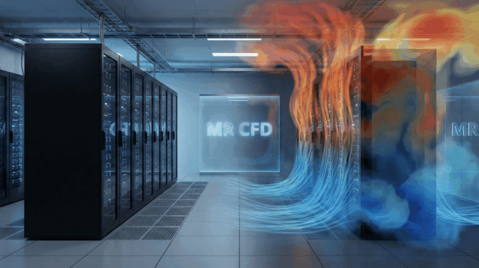
In the high-stakes world of data center operations, thermal management is not merely a technical necessity; it is a financial imperative. With cooling infrastructure often accounting for over 40% of a facility’s total energy consumption, the margin for error is non-existent. A single hotspot can lead to server degradation or catastrophic failure, while inefficient airflow results in a bloated Power Usage Effectiveness (PUE) ratio that drains operating budgets.
For decades, engineers relied on “rules of thumb,” spreadsheet calculations, and trial-and-error sensor placement to manage these environments. Today, those methods are obsolete. To guarantee uptime and energy efficiency, industry leaders turn to HVAC CFD analysis.
At MR CFD, we have spent over 20 years applying advanced Computational Fluid Dynamics (CFD) to the most complex industrial challenges. We know that a data center is a living, breathing entity where airflow dynamics change the moment a rack is populated or a tile is moved. This comprehensive guide serves as a blueprint for mastering data center thermal management, moving beyond basic monitoring to predictive physics-based simulation. Whether you are looking to retrofit an aging facility or design a hyperscale center from the ground up, understanding the physics of airflow is your key to unlocking ROI. 🚀
What Is HVAC CFD Analysis and Why Is It Critical for Data Centers?
HVAC CFD analysis is the application of numerical methods and algorithms to solve and analyze problems that involve fluid flows—in this context, the complex movement of air and heat within a mission-critical facility. It creates a “Digital Twin” of your data center: a physics-accurate virtual replica that simulates airflow velocity, pressure distribution, and temperature gradients across every cubic inch of the room.
Without CFD, facility managers and engineers are essentially “flying blind.” You might have sensors at the rack inlets and returns, but what happens in the empty space between the CRAC (Computer Room Air Conditioning) unit and the server? What happens under the raised floor?
Sensors provide point data—snapshot measurements of what is happening right now at specific locations. Computational Fluid Dynamics in HVAC provides field data—a continuous map of what is happening everywhere, and more importantly, what will happen if you change something.
By solving the Reynolds-Averaged Navier–Stokes (RANS) equations, CFD allows us to visualize the invisible. We can see the exact path a particle of cold air takes from the perforated tile to the server intake. We can identify where cold supply air bypasses the racks entirely and returns to the cooling unit wasted. Conversely, we can pinpoint where hot exhaust air recirculates back into the cold aisle, choking your servers.
In our consulting practice at MR CFD, we often find that clients are running their cooling units at 100% capacity yet still facing thermal alarms. The instinct is to buy more cooling power (CapEx). However, the diagnosis through CFD usually reveals that they don’t need more cooling; they need better airflow management. CFD provides the data to prove that distinction.
How Does Poor Airflow Directly Impact PUE and Operating Costs?

The physics of airflow translates directly to the economics of the facility. The primary metric for efficiency is Reducing PUE (Power Usage Effectiveness), calculated as the ratio of total facility energy to IT equipment energy. A perfect PUE is 1.0. Most legacy data centers struggle between 1.5 and 2.0. The culprit is almost always poor airflow hygiene, specifically recirculation and bypass.
The Cost of Recirculation
Recirculation occurs when hot exhaust air from the rear of the servers curls over the top or around the sides of the rack and mixes with the cold supply air at the server intake.
- Physics: This raises the rack inlet temperature.
- Response: To compensate, operators lower the setpoints on the CRAC units, chilling the supply air far below what should be necessary (e.g., supplying 55°F air to maintain 75°F at the inlet).
- Cost: Every degree you lower the setpoint increases chiller load and energy consumption non-linearly. Furthermore, server fans spin up to maximum RPM to compensate for the hotter air, drawing significantly more power at the rack level.
The Cost of Bypass Airflow
Bypass airflow is the opposite problem. It is premium, conditioned cold air that leaves the supply vent but never passes through a server. It travels straight back to the CRAC unit return.
- Physics: You are cooling air, moving it through the room, and returning it without it doing any work (heat removal).
- Cost: This creates a “low $\Delta T$” syndrome at the cooling unit. CRAC units operate most efficiently when there is a high temperature difference between return air and supply air. Bypass air lowers the return temperature, tricking the unit into throttling down dehumidification or cooling capacity while the fans still run at full power.
Through HVAC CFD analysis, we can quantify these losses precisely. We generate metrics such as the Supply Heat Index (SHI) and Return Heat Index (RHI). A high SHI indicates significant recirculation. By fixing these airflow patterns—often through low-cost containment strategies or tile rearrangement—we have helped clients reduce PUE from 1.8 to 1.3 without installing a single new cooling unit. That represents hundreds of thousands of dollars in annual OpEx savings. 💸
What Are the Key Challenges in Simulating Data Center Environments?
Simulating a data center is deceptive. It looks like a simple box with racks, but physically, it is one of the most chaotic environments to model. To achieve results that align with ASHRAE thermal guidelines, one must overcome several specific challenges.
1. Geometric Complexity and Scale Disparity
A data center spans multiple scales. You have the room scale (tens of meters), the rack scale (meters), and the server component scale (millimeters). Attempting to model every grill, cable, and screw in a full-room simulation results in a mesh count in the billions, which is computationally impossible to solve efficiently.
- The Challenge: How do you represent the detailed geometry of a server’s internal fans and heat sinks without crashing the solver?
- The MR CFD Solution: We utilize simplified “lumped parameter” models and porous media assumptions (detailed in the next section) to bridge these scales without losing accuracy.
2. Leakage and Imperfect Boundaries
No raised floor is perfectly sealed. There are cable cutouts, gaps between tiles, and leakage through the containment doors. In older facilities, under-floor obstructions (piping, massive cable bundles) create “dams” that block airflow, causing pressure variations that starve certain tiles of air.
- The Challenge: An idealized “CAD-perfect” model will show perfect cooling, but the real facility has hotspots.
- The MR CFD Solution: Experienced analysts know how to account for leakage percentages. We model the under-floor blockage explicitly. Our CFD simulation projects often begin with a detailed site survey to capture these “messy” realities, ensuring the digital twin behaves like the real room.
3. Buoyancy and Mixed Convection
Data center airflow is a mix of forced convection (driven by CRAC fans and server internal fans) and natural convection (buoyancy driven by heat). In high-density racks (20kW+), the heat plume is significant. If the simulation does not correctly account for buoyancy effects, it will fail to predict the hot air stratification near the ceiling, which is critical for return plenum design.
Overcoming these challenges requires not just software, but expertise. It requires an understanding of validation against experimental data to know when an assumption is valid and when it introduces error.
Step-by-Step: How Do We Execute a High-Fidelity HVAC CFD Analysis?
Executing a simulation that is accurate enough to base million-dollar decisions on requires a rigorous workflow. At MR CFD, we follow a structured approach to ensure every hvac cfd analysis meets the highest engineering standards.
How Should We Model Complex Geometries like Server Racks and CRAC Units?

The geometry setup is the foundation of the analysis. The most critical decision is how to represent the server racks and CRAC units.
The Porous Media Approach: We rarely model the individual servers inside a rack for a full-room simulation. Instead, the rack is modeled as a “black box” fluid zone with porous media properties.
- Inertial and Viscous Resistance: We assign resistance coefficients that mimic the pressure drop across the servers based on the manufacturer’s fan curves. This ensures the correct pressure drop ($\Delta P$) occurs from the cold aisle to the hot aisle.
- Heat Generation: The IT load (kW) is applied as a volumetric heat source within this zone.
- Flow Rate: Based on the $\Delta T$ and heat load, we impose momentum sources to replicate the server fans pulling air through.
CRAC Unit Modeling: Similarly, CRAC unit airflow simulation does not require modeling the internal compressor or coils. We model the intake and supply faces. The supply face is given a velocity inlet boundary condition with a specified temperature and flow rate, while the return is a pressure outlet.
Trade-offs: This approach reduces mesh count from billions to millions, allowing for faster iteration times while maintaining server room airflow modeling accuracy within 5-10% of reality.
Which Turbulence Models Are Best Suited for Indoor Airflow?
Selecting the right turbulence model is vital for predicting how jets of cold air mix with the ambient room air.
- Standard k-epsilon ($k-\epsilon$): This is the workhorse of the industry. It is robust, converges relatively quickly, and provides reasonable accuracy for fully turbulent flows. For general PUE calculations and macro-airflow patterns, this is often sufficient.
- Realizable $k-\epsilon$: This is a refinement of the standard model. It performs significantly better for flows involving rotation, strong streamline curvature, or separation—common in CRAC unit discharges or near perforated tiles with high-velocity jets.
- SST $k-\omega$: This model is superior for near-wall treatment and heat transfer at boundary layers. However, it is computationally more expensive and often unnecessary for room-level simulations unless we are looking at detailed heat transfer on a specific component.
- Zero-Equation (Indoor Zero Equation): Specialized for HVAC, this algebraic model is very fast and stable for predicting indoor airflow distribution where turbulence is low.
At MR CFD, we typically start with Realizable $k-\epsilon$ for data centers, as it offers the best balance of speed and accuracy for predicting jet throw from perforated tiles and the mixing of hot and cold airstreams.
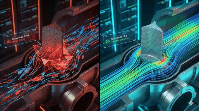
How Do We Ensure Mesh Independence for Reliable Results?
A common mistake in amateur CFD is using a coarse mesh to get a “pretty picture” quickly. This leads to numerical diffusion, where sharp temperature gradients (like a hot exhaust plume) are artificially smeared out, hiding potential hotspots.
To ensure E-E-A-T (Expertise, Authoritativeness, and Trustworthiness) in our results, we perform a Grid Independence Study.
- Coarse Mesh: Run the simulation with 2 million cells.
- Medium Mesh: Refine to 5 million cells.
- Fine Mesh: Refine to 10 million cells.
We compare key metrics—such as the average rack inlet temperature or the pressure drop across the floor—across these three meshes. If the results change significantly between the Medium and Fine mesh, the solution is “grid dependent,” and we must refine further. We only consider the results valid once the solution stabilizes and becomes independent of the mesh density. This rigorous verification is what separates a pretty animation from an engineering tool. ✅
Case Study: How Can CFD Simulation Fix Hotspots and Implement Containment Strategies?

Let’s look at a representative engagement where MR CFD was brought in to assist a Tier 3 data center facing critical thermal issues.
The Scenario: The facility was operating a raised-floor plenum system with alternating hot and cold aisles. Despite having a total cooling capacity that exceeded the IT load by 30%, specific high-density racks (blade servers) in Row 4 were triggering high-temperature alarms (inlet temps > 80°F). Operators were responding by lowering CRAC setpoints to 60°F, driving PUE up to 1.9.
The CFD Diagnosis: Our hvac cfd analysis revealed two critical issues:
- Plenum Maldistribution: A massive bundle of under-floor cabling was blocking airflow to Row 4, reducing pressure at the perforated tiles.
- Short-Circuiting: Hot exhaust air from Row 3 was recirculating over the top of the racks into the intake of Row 4.
The Virtual Solution (Digital Twin Testing): Before spending a dime on hardware, we tested solutions in the virtual model:
- Scenario A: Moving the floor tiles. (Result: Insufficient improvement).
- Scenario B: Adding Hot aisle vs. cold aisle containment. We modeled a Cold Aisle Containment (CAC) system, capping the cold aisle with a roof and doors.
The Result: The simulation of Scenario B showed that by physically isolating the cold air, the pressure in the cold aisle would equalize, overcoming the cable blockage. The containment prevented the hot air recirculation entirely.
Implementation & Validation: The client installed the CAC system.
- Rack Inlet Temps: Dropped from 82°F to a uniform 72°F.
- CRAC Setpoints: Were raised from 60°F to 74°F.
- PUE Impact: Dropped from 1.9 to 1.6 immediately.
What Happens When a CRAC Unit Fails? (Transient Analysis)
The client had one final question: “If CRAC Unit 3 fails, how long do we have before the servers overheat?”
Steady-state CFD cannot answer this. We moved to transient (time-dependent) simulation. By simulating the sudden shutdown of one unit, we modeled the “thermal ride-through” time.
- Minute 0-2: The containment volume held enough cold air buffer.
- Minute 5: Temperatures in Row 4 began to climb past ASHRAE allowable limits.
This data allowed the client to adjust their backup generator startup protocols, ensuring they could bring backup cooling online within the 5-minute safety window. This level of insight is essential for risk mitigation and disaster recovery planning. 📉
Why Choose MR CFD for Your HVAC Simulation Projects?
Navigating the complexities of fluid dynamics requires more than just software; it requires a partner who understands the intersection of physics and business.
MR CFD offers a unique value proposition for data center operators and engineering firms:
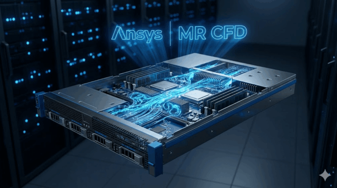
- Deep Expertise: With two decades of experience, we have seen—and solved—every airflow problem imaginable. We are certified Ansys experts who contribute to the development of best practice methodologies in the industry.
- High-Performance Computing (HPC): Data center models are massive. We possess our own dedicated HPC clusters, allowing us to run high-fidelity, transient simulations that would crash a standard engineering workstation.
- Knowledge Transfer: We don’t just hand you a report and leave. For teams that want to build internal capabilities, we offer comprehensive Ansys Fluent training for HVAC. We teach your engineers how to perform rack inlet temperature optimization and data center cooling optimization themselves.
Whether you need a turnkey consulting solution to fix an immediate crisis or a long-term partner to validate your new facility designs, MR CFD delivers physics-based certainty in an uncertain world.
Frequently Asked Questions
What is the typical ROI of an HVAC CFD analysis for a data center?
The Return on Investment (ROI) is often immediate and substantial. By identifying inefficiencies like bypass airflow and recirculation, CFD analysis typically uncovers energy savings of 10% to 20%. For a medium-sized data center, this translates to tens or hundreds of thousands of dollars annually in reduced electricity costs. Furthermore, the prevention of a single catastrophic downtime event—caused by undetected hotspots—can save millions in lost revenue and hardware replacement. The cost of the study is usually a fraction of the first year’s energy savings.
Can MR CFD simulate emergency cooling failure scenarios?
Yes, this is one of our core specialties. Using transient (time-dependent) solvers, we can simulate the exact timeline of a cooling failure. We can predict how quickly temperatures will rise in specific aisles if a CRAC unit fails or if utility power is lost and the facility is running on thermal inertia before generators kick in. This “thermal ride-through” analysis is critical for validating Service Level Agreements (SLAs) and designing robust emergency response protocols.
Do I need my own Ansys license to hire MR CFD for consulting?
No, you do not need your own software or hardware. When you hire MR CFD for MR CFD simulation projects, we utilize our own commercial Ansys licenses and our in-house High-Performance Computing (HPC) infrastructure. We handle the entire computational workload. We simply require your facility data (geometry, heat loads, etc.), and we deliver the final comprehensive report, visualizations, and design recommendations.
How accurate is CFD compared to real-world measurements?
When executed correctly using E-E-A-T methods—such as proper grid independence studies, appropriate turbulence modeling (like Realizable $k-\epsilon$), and accurate boundary condition inputs—CFD is extremely accurate. We typically see a correlation within 5-10% between our simulation predictions and actual physical measurements. We often perform a validation against experimental data phase during our projects, where we calibrate the model against existing sensor data to ensure the “Digital Twin” matches reality perfectly before testing new changes.
Does MR CFD offer training for in-house engineering teams?
Yes, we are passionate about education. We offer specialized Ansys Fluent training for HVAC and data center applications. These courses are not generic; they are tailored to the specific challenges of the industry, covering porous media modeling, fan curves, and contaminant transport. Whether you are a beginner or an advanced user, our courses are designed to help your team build internal competency in Computational Fluid Dynamics in HVAC.
What information is required to start a data center CFD project?
To kick off a high-fidelity analysis, we typically need:
- Geometry: CAD drawings or architectural floor plans (DWG/DXF) of the room, including plenum depth and ceiling height.
- Cooling Specs: Datasheets for CRAC/CRAH units (airflow CFM, cooling capacity, supply temperatures).
- IT Load: A layout map showing the heat load (kW) per rack or the total IT load distribution.
- Floor Details: The open area percentage of the perforated tiles.
- Obstructions: Information on major under-floor obstructions like piping or cable trays.
Related Posts
Errors Occurring in Simulations with ANSYS Fluent: A Technical Guide to Convergence & Stability
ANSYS Fluent simulates engineering problems based on the Finite Volume Method (FVM). Consequently, the errors…
How Ansys HPC Servers Accelerate Your Fluent Dynamic Simulations
We have all been there. You hit “Calculate” on a transient simulation, and the estimated…

Ansys HPC Case Study: Accelerating a 120-Million Cell Simulation Using MR CFD’s Ansys HPC Service
In the high-stakes world of aerodynamics, fidelity is everything. But as engineers, we often hit…

Comments (0)