Façade Design Effect on Passive Ventilation of Buildings
Original price was: $540.00.$270.00Current price is: $270.00. Student Discount
- In this project, the effects of façade design on passive ventilation of a building numerically investigated by ANSYS Fluent.
- Studying thermal condition from energy aspect and ventilation (ACH).
- Façade design as a passive ventilation system
- Solar ray tracing effect on heat transfer
To Order Your Project or benefit from a CFD consultation, contact our experts via email ([email protected]), online support tab, or WhatsApp at +44 7443 197273.
There are some Free Products to check our service quality.
If you want the training video in another language instead of English, ask it via [email protected] after you buy the product.
Description
Façade Design Effect on Passive Ventilation of a Building, Industrial Application
Introduction
One side of a building structure, which is often in direct contact with the ambient environment, is known as the façade (see Fig.1). Nowadays, facade design’s effect on the passive ventilation of buildings is one of the major fields of interest for architectural and energy engineering.
Despite the fact that it gives the building a distinctive appearance, it is one of the most crucial components of the overall design of the building from an energy aspect. A building’s façade may take on a variety of shapes and sizes, leading to various thermal comfort and energy consumption.
In fact, it is one of those elements of the building that gives engineers the freedom to provide part of the needed energy using Passive ventilation systems.

Project Description of Façade Design Effect on Passive Ventilation
In this project, a three-floor apartment located in the capital city of the New South Wales state, Sydney, is simulated. This study investigates different façade conditions to reach the best-case scenario, ensuring natural ventilation, best thermal condition and air change per hour (ACH).
The first step gathers general information to estimate the geographical and thermal conditions. Sydney, with 151.20 longitude and -33.865 latitude coordinates, experiences the coldest weather condition in July & August, with an average temperature of 283K. Additionally, the building got 3 floors with an 80 m^2 cross-section area and 2.8m height.
The client also set a limitation and asked for glass as façades material. As mentioned, the two prior design targets are to provide part of the energy need of the building and natural ventilation measured by the ACH parameter. Therefore, our experts came up with 3 different facade designs predicted to satisfy the targets.
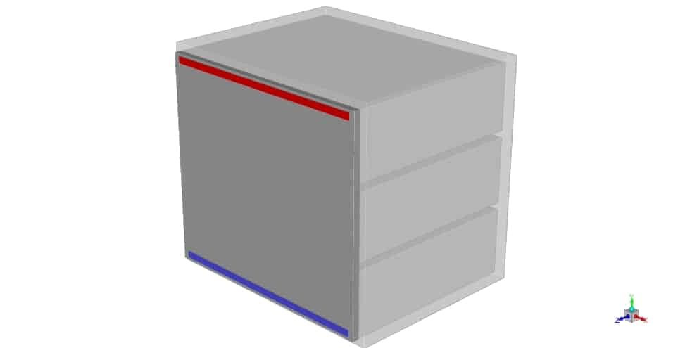
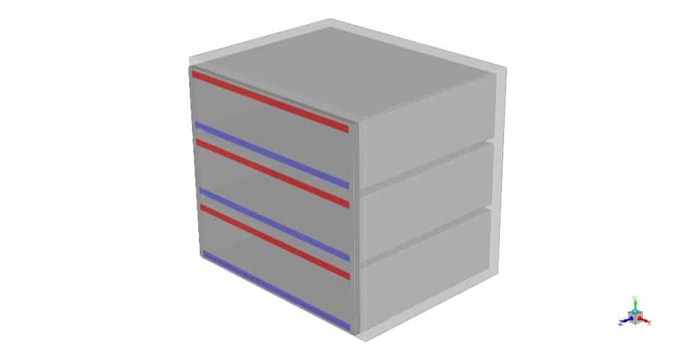
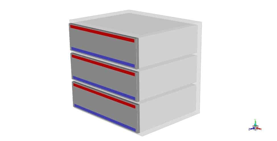
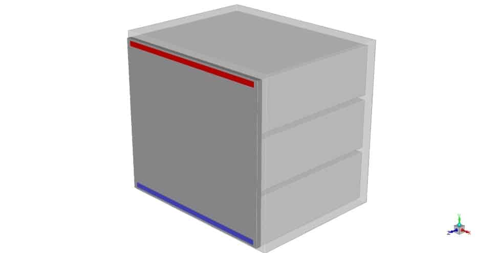
Case 1 is dedicated to the façade extended fully to cover the building’s front view. Plus, it got a separate inlet and outlet vent. A schematic of each case design is depicted. Note that the outlets and inlets are colored in red and blue colors.
case 1:
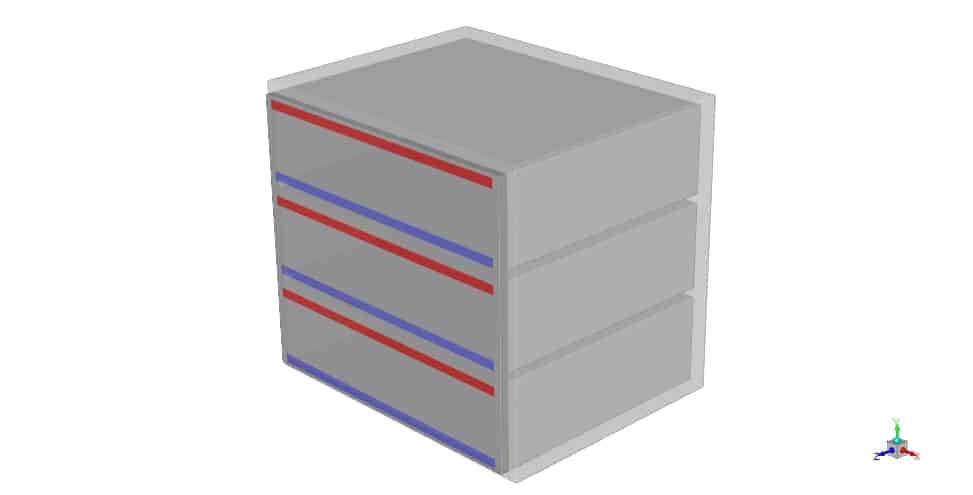
In case 2, the inlet and outlet vents are installed on a modified façade. In this case, the façade is established from three separate parts, each for a different floor and not in contact with each other.
case 2:
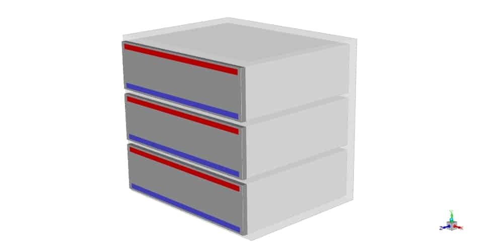
In the third case, we extended the facade like in the first case, but one inlet and outlet are implemented.
case 3:
Figure 2- a) case 1 b) case 2 with separate façade parts c) case 3 with one inlet and outlet
Analysis of Façade Design Effect on Passive Ventilation
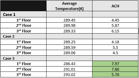
After the simulation, we gathered the results in the table below.
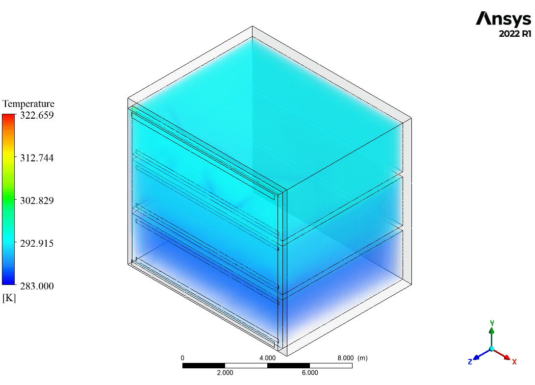
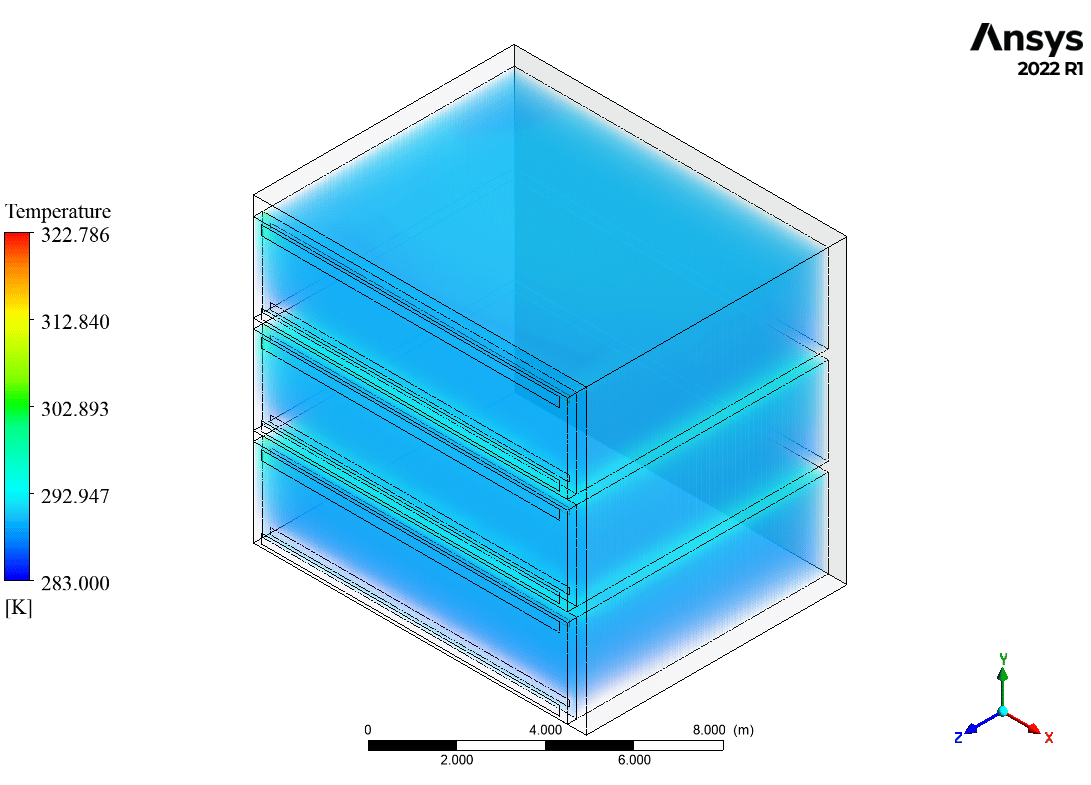
As can be seen, the temperature distribution is uniform in cases 1&2, while there is a distinct difference between the three floors of case 3. It is also visible in the temperature volume rendering of case 3 depicted in figure 3c.
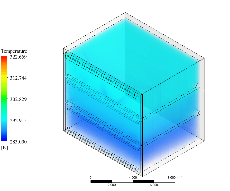
Hence, from the aspect of energy, we need to determine the building’s average temperature, which is 289.58K, 289.3K, and 290.15K for cases 1 to 3, respectively.
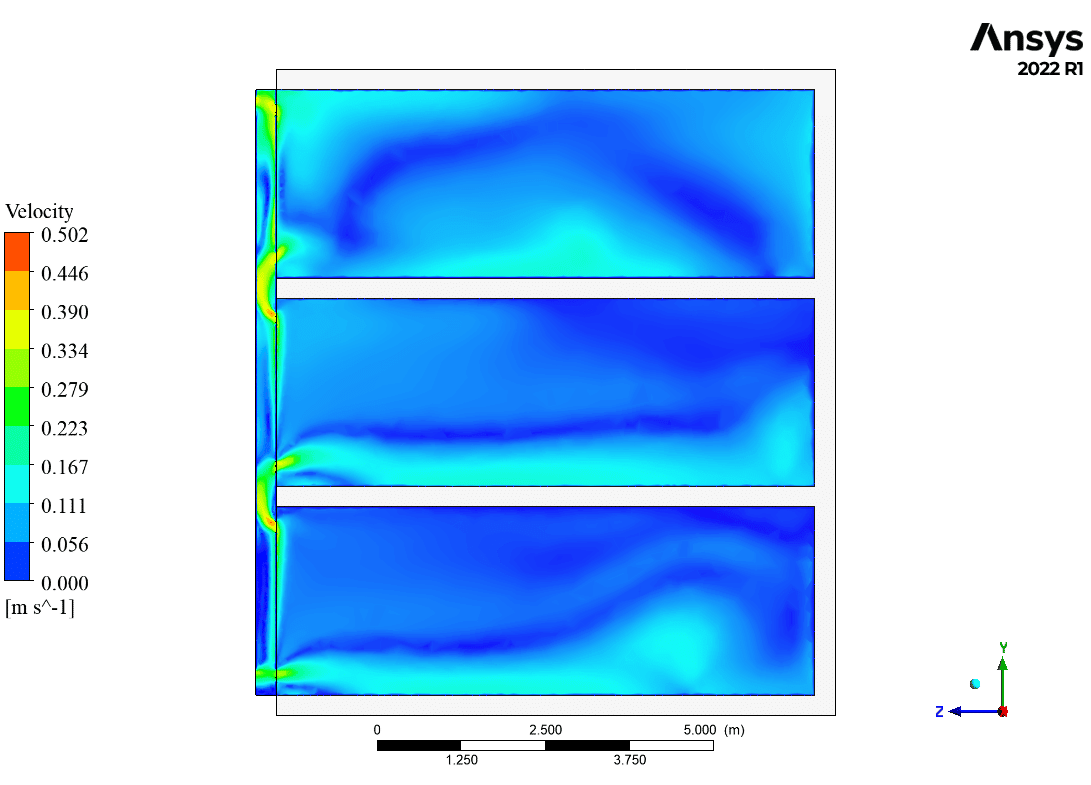
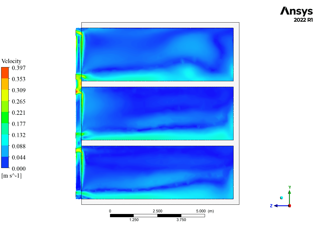
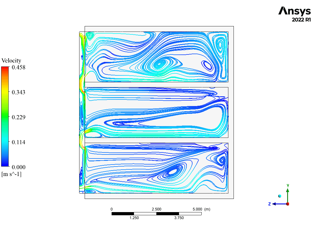
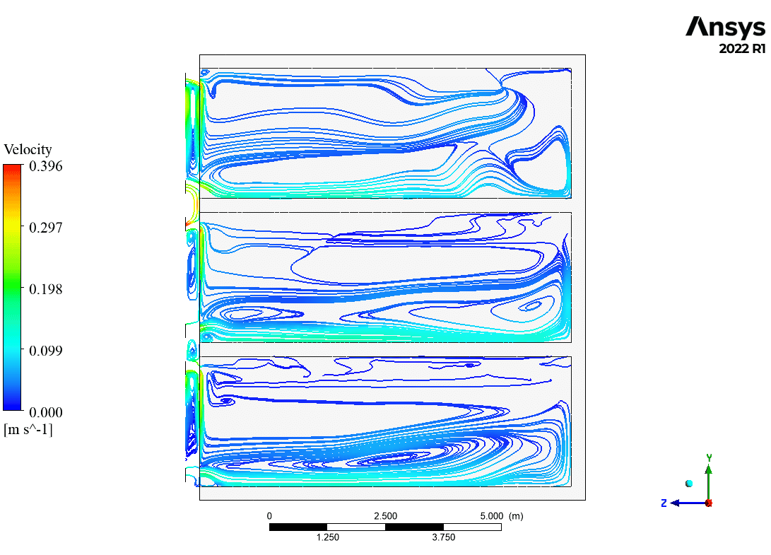
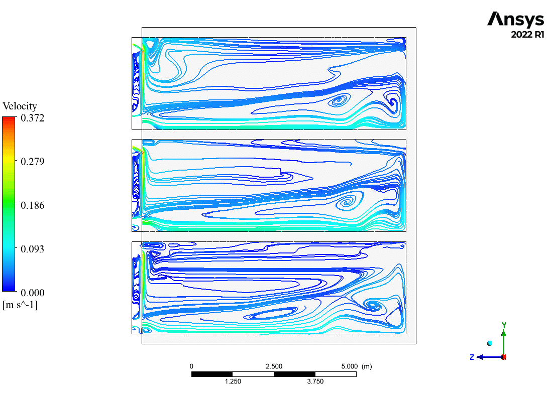
On the other side, the façade geometrical design and vents arrangements give us different ventilation conditions. Based on the reported data and streamline contour (Fig 4), the reduction in vents numbers successfully trapped the hot air in the façade zone. It plays a pivotal role as an insulation layer toward cold ambient air.
To conclude, the design of case 3 leads to the best thermal and ventilation condition and can fulfill the targets compared to the other designs.
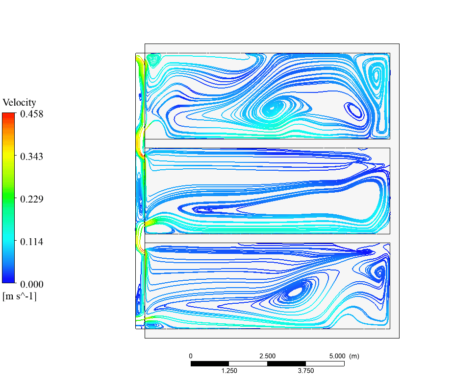
It should be reminded that the purpose of using passive ventilation systems is just to benefit from their effects. So, it cannot satisfy the living conditions. Thus, we neglect the inappropriate thermal condition of the first floor.




Miss Julianne Murphy I –
What seasonal differences could affect the effectiveness of the façade designs in terms of passive ventilation?
MR CFD Support –
The seasonal variations, such as changes in wind speed, direction, and outdoor temperature, play a crucial role in the effectiveness of façade designs for passive ventilation. During summer, higher temperatures might require different ventilation strategies compared to winter when the focus would be on preventing heat loss and maximizing solar gain.
Amir Brakus PhD –
This product is simply amazing! The analysis on façade design and its impact on passive ventilation doesn’t only help engineers but also informs architectural approaches significantly. The case studies are practical and the graphical representations are fantastic. Efficient passive ventilation design is critical to both energy savings and comfort in urban structures. Excellent work by MR CFD!
MR CFD Support –
Thank you for your kind words! We are thrilled to hear that you found our analysis on façade design for passive ventilation insightful and practically useful. It’s great to know that the quality of our graphical representations met your expectations. At MR CFD, we strive to provide informative and valuable content. Your acknowledgment motivates us to continue delivering high-quality work. If you have any further questions or need assistance with other projects, please do not hesitate to reach out to us.
Mrs. Agnes Walker –
The comprehensive results seem to reflect the successful outcomes of the facade designs in terms of thermal comfort and ventilation. I really appreciate the depth of analysis carried out. Great job to the whole team!
MR CFD Support –
Thank you for your positive feedback. We’re thrilled to hear that our detailed analysis has met your expectations and provided the valuable insights needed for effective facade design in achieving ideal thermal and ventilation conditions. Your appreciation motivates us to maintain our high standards of research and analysis. Thank you for choosing our services!
Jaquan Ferry –
What was the average temperature achieved in each façade design case and how does this relate to the building’s energy requirements and comfort levels?
MR CFD Support –
The average temperature achieved in each façade design case was 289.58K for case 1, 289.3K for case 2, and 290.15K for case 3, respectively. These temperatures help to understand which façade design creates a more thermally comfortable environment while considering the energy consumption necessary to maintain such a temperature. Case 3, with the best thermal condition, is indicated to potentially fulfill the building’s energy targets while also ensuring a comfortable living environment.
Dr. Shad Hessel III –
This review has shared remarkable insights into the impact of façade design on passive ventilation. I especially found the comparative analysis between the different façade cases compelling. Which one of the cases would provide the most ideal combination of visual aesthetics and ventilation efficiency based on your findings?
MR CFD Support –
Thank you for your interest and kind words about the study. Case 3 provides an optimal balance between aesthetics and efficiency. While it features an extended façade similar to Case 1, the single inlet and outlet implementation permits an effective passive ventilation system. It traps warm air, creating an insulation layer which enhances both the building’s thermal performance and visual appeal, making it the best solution per our analysis.
Sabina Hartmann –
Is it possible to use different materials for the façade in case 1 to further improve thermal performance, or is glass the only option mentioned in the limitations set by the client?
MR CFD Support –
In the given scenario, the client specified glass as the material for the façade. In case 1, it extends fully to cover the building’s front view. If the client’s requirements allow, exploring other materials could potentially enhance the thermal performance. However, as per the description and limitations provided, only glass is used for the façade design in this simulation study.
Curt Stracke –
I am thoroughly impressed with how the facade design impacts passive ventilation! Great work in exploring the three different designs to optimize for thermal comfort.
MR CFD Support –
Thank you very much for your positive feedback! We’re delighted to hear that the analysis of various facade designs for enhancing passive ventilation met your expectations and provided valuable insights. Your compliment encourages us to continue our pursuit of excellence in CFD simulations. Should you have any further inquiries or need assistance with similar projects, don’t hesitate to reach out.
Prof. Nasir Schultz MD –
The analysis results are impressive. Could the streamline contour differences between the case studies affect the overall ventilation strategy for each facade design?
MR CFD Support –
Based on the project’s results, the layout and design of the vents significantly influence the passive ventilation performance. The streamline contours provide valuable insights into the flow patterns, which is important for understanding how air moves through and around the structures. Therefore, distinctions between streamline contours across different case studies indeed affect the overall ventilation strategy for each façade design, contributing to either improved or diminished natural ventilation effectiveness.
Tess Gleichner II –
I am impressed with the detailed analysis on the impact of facade design on passive ventilation. The concept of using the facade as both a design and energy-modulating element is fascinating and will gain even more importance as we focus on sustainable building practices.
MR CFD Support –
Thank you so much for your kind words. We are pleased to hear that you appreciate the detailed approach in analyzing the influence of facade design on passive ventilation. It’s exciting to witness growing interest in sustainable innovations in architecture, and acknowledgment from valued customers like you is very encouraging for our team at MR CFD.
Miss Aiyana Goldner –
The project nicely illustrates how facade design impacts passive ventilation, but could you provide more details on the specific dimensions or orientation of inlets and outlets?
MR CFD Support –
Unfortunately, as this is an AI-generated conversation, I do not have access to specific dimension details beyond the information already provided in the project summary. MR CFD Company provides extensive simulation services that can offer precise measurements and configurations based on bespoke simulations tailored to client needs.
Maximilian Hane –
The review is superbly informative! May I ask if the study considered the impact of sun shading or façade orientation as additional factors when assessing the façade design’s influence on passive ventilation?
MR CFD Support –
We appreciate your question! Indeed, the impact of sun shading and façade orientation are critical factors in passive building design. This study focused on the geometrical design and vents arrangements. For a more comprehensive approach, further simulations considering sun shading and orientation could be conducted to enhance the effectiveness of passive ventilation.
Mr. Tommie Johns II –
The analysis seems comprehensive, but I would like to know more about how passive ventilation was measured across different façade designs. Could you elaborate on how this was quantified and translated into the ACH metric needed to assess energy performance?
MR CFD Support –
In simulation analyses, the amount of airflow passing through a room divided by the volume of the room provides the air change per hour (ACH) metric. Quantifying ACH for different façade designs involves tracking the rate of airflow into and out of the building for each design and comparing this rate with the internal volume of the building. Additionally, simulations used streamlines and airflow patterns to visually show ventilation efficiency and areas where air might be trapped. A detailed CFD analysis allows us to pinpoint exactly how different façade geometries influence these air changes, providing a quantitative measurement that feeds into the overall assessment of passive ventilation effectiveness.
Dr. Jackson Bernier Jr. –
Was CFD used to calculate the air change per hour (ACH) in the different façade designs, or were other methods applied as well?
MR CFD Support –
The ACH measurement was performed using CFD simulations. Through these simulations, the ventilation rates and airflow patterns were detailedly analyzed for the various façade designs, allowing for precise calculation of air changes per hour relevant to each design.
Karli Altenwerth –
Thank you for providing such an insightful analysis on the impacts of façade design on passive ventilation! The thorough investigation of temperature and ventilation outcomes across different façade scenarios really highlights the importance of thoughtful architectural design in building energy efficiency. Your findings offer valuable evidence supporting the case for integrated façade and ventilation strategies, which can greatly contribute to the sustainable building practices community. Keep up the incredible work!
MR CFD Support –
We really appreciate your positive feedback! It’s wonderful to hear that our analysis on façade design’s effect on passive ventilation was both insightful and useful to you. Our goal is to support sustainable architecture by providing detailed and practical CFD insights. Thank you for recognizing our efforts, and please don’t hesitate to reach out if you need further assistance or if you have more projects that you’d like to explore with us!
Ocie Wolf –
Your project on façade design’s impact on passive ventilation was enlightening. However, do you by chance have any user testimonials or feedback on how these designs have been implemented in real buildings and their effectiveness?
MR CFD Support –
We really appreciate your interest and are glad you found the façade design project insightful. Unfortunately, we cannot provide real building implementation testimonials directly since our role is predominantly in simulation and analysis. Yet, we signify the efficacy of our designs through detailed computational models and encourage professionals in the field to share their practical application experiences.
Providenci Mayert –
I’m intrigued by how the façade design affects air flow and temperature distribution. Can you explain which software or method was used to simulate the ventilation and thermal conditions for each façade design?
MR CFD Support –
The simulations in this project were most likely performed using computational fluid dynamics (CFD) software, which can handle complex geometries and interactions between air flow and structural elements. ANSYS Fluent or a similar software could have been utilized for analyzing the passive ventilation and temperature distribution across the various façade designs. This software is capable of predicting the airflow patterns, temperature fields, and assessing the performance of ventilation systems by numerical methodologies.
Kimberly Brekke –
The realistic and detailed approach taken in this study impresses me. How precisely can the simulation predict the thermal comfort levels for occupants?
MR CFD Support –
The ability to predict thermal comfort levels using simulation is contingent on the accuracy of the model and its boundary conditions. Our simulation employs detailed geometry and precise physical properties for materials and environmental conditions to give you a close approximation of likely thermal comfort. Occupants’ comfort, however, is also influenced by individual preferences and local environmental fluctuations, which can complicate precise predictions.
Waldo Towne –
This CFD project about facade design enhancing passive ventilation was thoroughly enlightening! I’m intrigued by the specific changes between each case and how they affected the temperature uniformity and ACH – the comparative analysis provided me with a clear understanding of the impact of facade design. Given all variables were consistent across cases, these insights are particularly applicable for architects and engineers in the field.
MR CFD Support –
Thank you for your positive feedback and for appreciating the thorough analysis of our study! We are elated to know that the detailed comparative information has been instrumental to your understanding of facade design and its influence on passive ventilation. It’s always our goal to provide valuable insights that can guide design choices for professionals. Should you have any further inquiries or need more insight into our research, feel free to reach out!