
ANSYS STRUCTURAL: I-Beam Static Simulation
$180.00 Internship
- This product simulates an I-Beam using ANSYS Static Structural software.
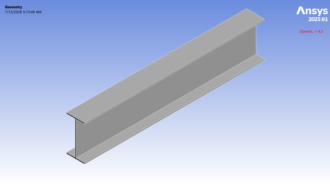
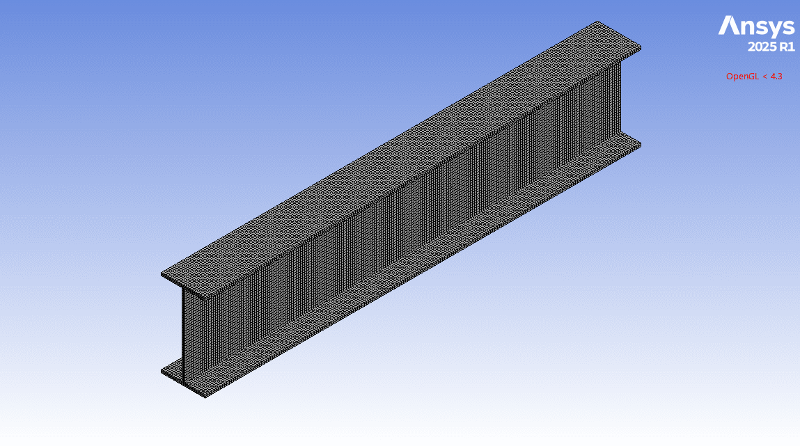
- We model the 3D geometry with the Design Modeler software and mesh it as a Structured grid.
- We use Fixed Support and Pressure Load as the boundary load conditions.
- The pressure load is defined over time (loading and unloading).
To Order Your Project or benefit from a CFD consultation, contact our experts via email (info@mr-cfd.com), online support tab, or WhatsApp at +44 7443 197273.
There are some Free Products to check our service quality.
If you want the training video in another language instead of English, ask it via info@mr-cfd.com after you buy the product.
Description
ANSYS Static Structural: I-Beam Analysis under Pressure Load and Fixed Support
Description
In this project, we present a structural simulation of an I-Beam in ANSYS Static Structural.
Beams are structural components that carry transverse loads which mainly due to bending phenomena. These beams are widely used in buildings, bridges, and other load-bearing structures. Beams are manufactured in various cross-sections, such as rectangular, circular, T-section, and I-section.
For the present study, a beam containing an I-shaped cross-section is modeled. I-beams are one of the most popular and efficient. In these I-sections, the material is concentrated in the top and bottom flanges, causing a high strength-to-weight ratio.
The goal of this study is to evaluate the structural response of the beam under the bending load, in the form of deflection and stress distributions.
Methodology
First, we modeled the geometry of the beam with Design Modeler software. The computational domain is a horizontal beam with an I-section. Second, we meshed the domain. Because of the uniform and symmetrical construction of the beam, a structured mesh was created, generating 31,800 elements. Finally, we completed the simulation and calculations with ANSYS Static Structural software.
The structural steel is determined as the material for this beam. We considered that the horizontal beam is completely constrained at one end (without any free movement), while a continuous pressure load is applied to the top face of the beam. Therefore, for the load conditions, we used a fixed support and a pressure load.
Note that the pressure load was defined as first gradually increasing to a maximum value (5 MPa) and then gradually decreasing. In other words, it represents a short-term loading-unloading cycle.
Conclusion
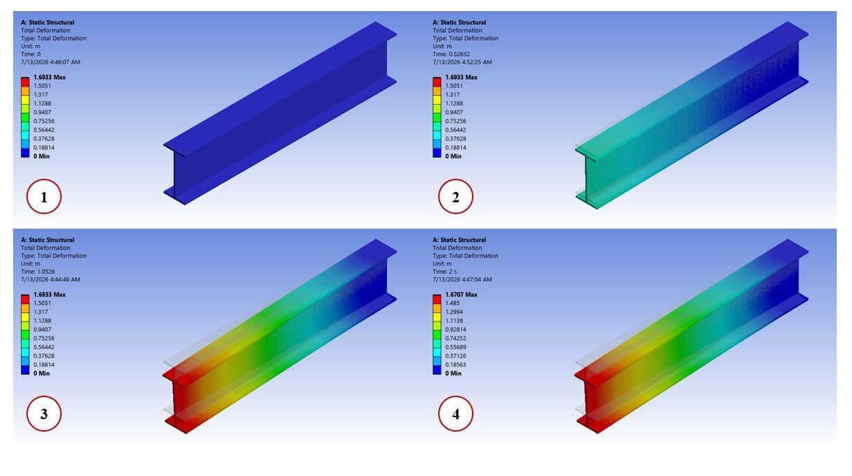
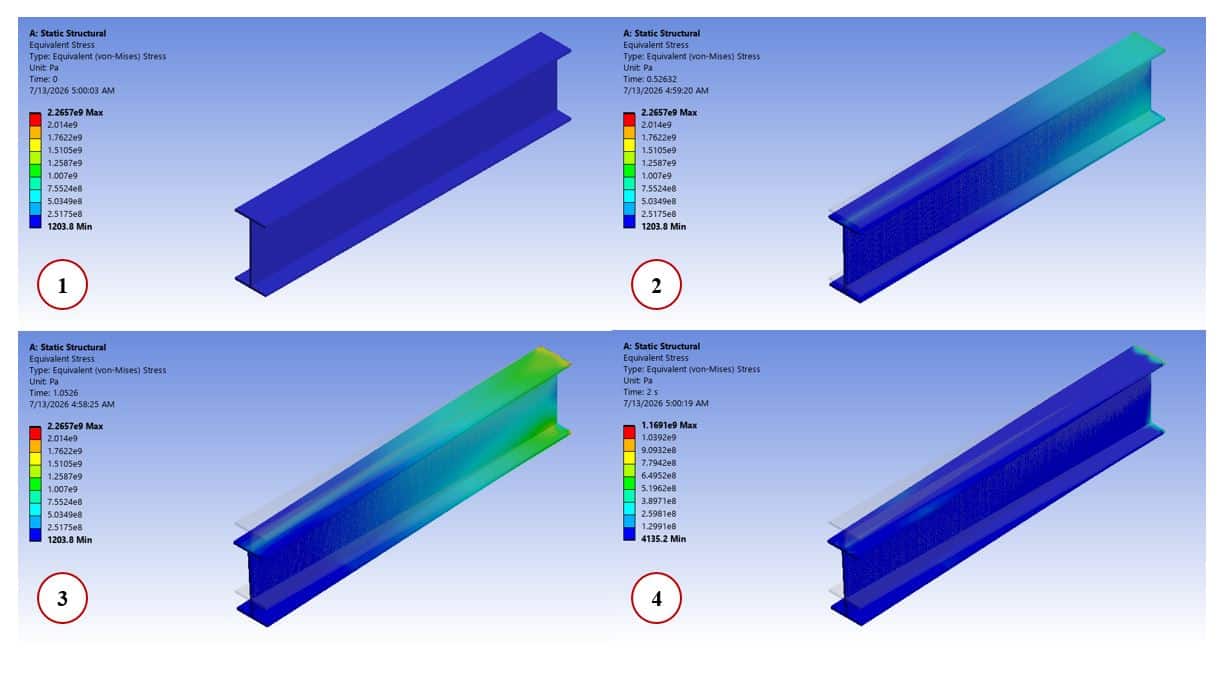
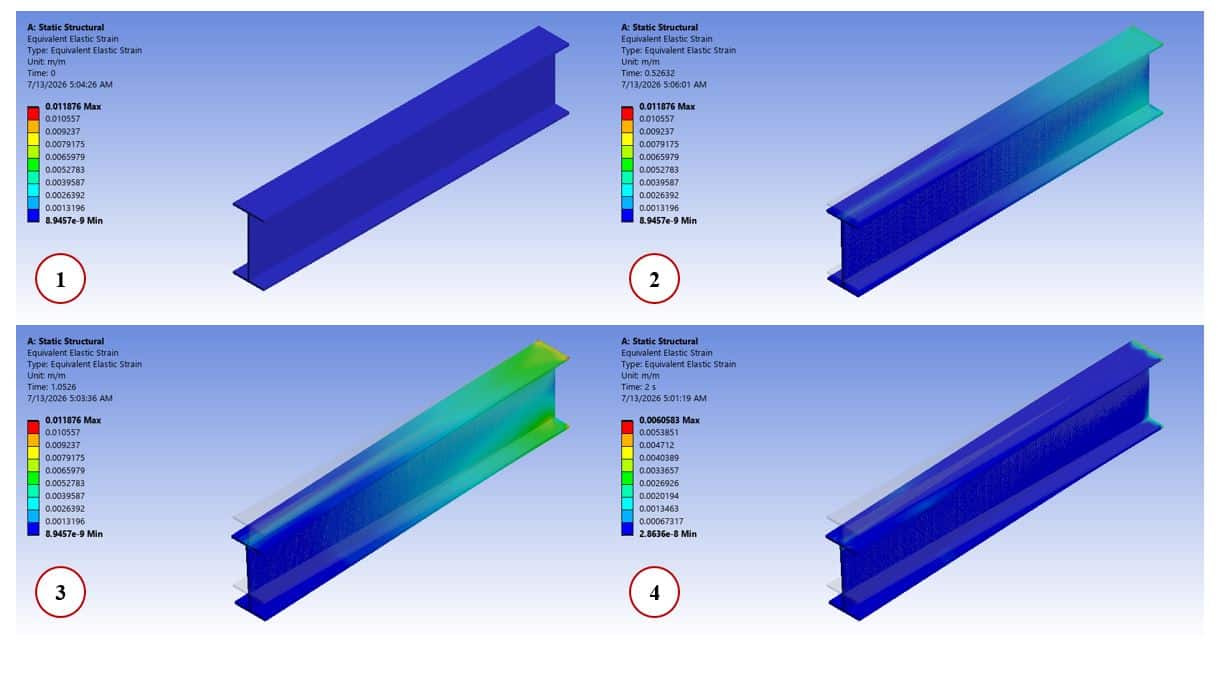
After the calculations, we obtained the contours of total deformation, equivalent strain, and equivalent (von Mises) stress over the beam. We studied these deformation and stress distributions over time (from loading to unloading).
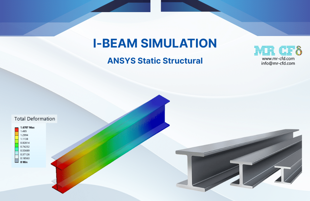
The total deformation distribution shows that maximum deflection occurs at the free end of the beam, while the first end becomes fixed. This is fully consistent with the behavior of the beam bending. The stress distribution indicates that the maximum value appears near the fixed support, where the bending moment is highest.
In addition, the results show that after unloading from the beam, the increase in deformation, strain, and stress stops.
You must be logged in to post a review.

 Talk On WhatsApp
Reviews
There are no reviews yet.