Learn Ansys Meshing Course: Master 7 Critical Skills
It’s a scenario I’ve seen play out dozens of times: a junior engineer spends days setting up a complex simulation, launches the solver, and watches with anticipation. The residuals start to drop, but after 500 iterations, they suddenly spike, and the dreaded “divergence” error appears. The culprit isn’t the physics setup or the boundary conditions; it’s a= poor-quality mesh at a critical boundary layer, a fundamental flaw that doomed the simulation from the start. This isn’t just a hypothetical; it’s the reality of computational fluid dynamics (CFD). Meshing isn’t just a preliminary step; it’s the absolute foundation upon which every reliable simulation is built.
Industry data and my own 15+ years of experience confirm that meshing and geometry preparation consistently consume 50-70% of the total simulation preparation time. Getting it wrong means wasted hours, blown budgets, and unreliable results. Getting it right, however, means faster convergence, higher accuracy, and confident engineering decisions. The gap between a frustrating simulation experience and a predictable, powerful one is almost always bridged by mastering the art and science of mesh generation.
This article demystifies what a comprehensive learn ansys meshing course should teach. We’ll break down the curriculum into seven core skill categories that transform beginners into confident, efficient practitioners. At MR CFD, we’ve structured our training around this exact progression, moving from foundational geometry cleanup to advanced hybrid meshing strategies. By the end, you’ll understand not just how to create a mesh, but why specific choices lead to simulation success.
Why Is Meshing the Most Critical Skill in CFD Simulation?
Meshing expertise is the primary differentiator between successful CFD projects and failed ones. The reason is simple: the mesh is the discrete domain on which the governing equations of fluid dynamics (the Navier-Stokes equations) are solved. The quality, structure, and resolution of this domain directly dictate the solution accuracy, convergence stability, and computational cost of your simulation. A poor mesh introduces numerical errors that can corrupt your results or prevent the solver from converging at all.
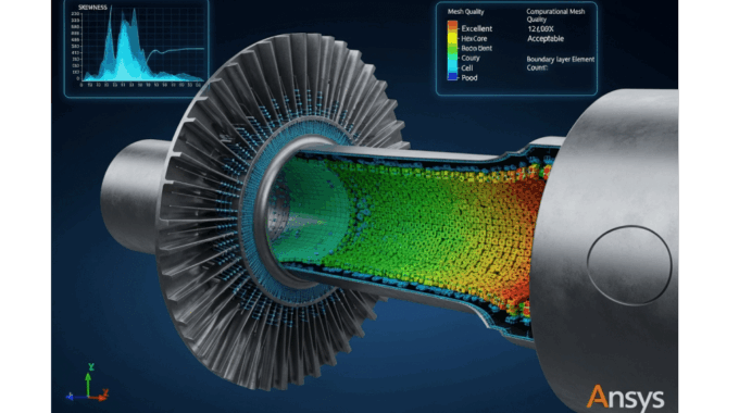
Consider a recent consulting project on a centrifugal compressor. The initial mesh, created with default settings, resulted in a stalled solution and non-physical pressure predictions. By systematically improving the mesh quality metrics—specifically orthogonality and aspect ratio in the blade passages—by just 15%, we not only achieved a stable convergence but also reduced the total solve time by nearly 40%. This isn’t an anomaly; it’s a direct demonstration of how a high-quality mesh enables the solver to work more efficiently, leading to faster, more reliable outcomes.
How Does Mesh Quality Directly Impact Your Simulation Accuracy?
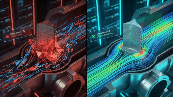
The connection between mesh quality and accuracy lies in how the solver approximates gradients (like velocity, pressure, and temperature) across the faces of mesh cells. Poor quality cells introduce numerical diffusion, a form of error that artificially smears these gradients, much like a blurry photo obscures fine details. Key metrics directly correlate to this:
- Skewness: This measures how distorted a cell is from its ideal shape (e.g., an equilateral triangle). High skewness leads to inaccurate gradient calculations. For complex flows, I always target a maximum skewness below 0.85, and ideally below 0.75 in critical regions.
- Aspect Ratio: This is the ratio of the longest to the shortest edge of a cell. High aspect ratios are acceptable in boundary layers where gradients are one-directional, but problematic in isotropic flow regions, as they compromise gradient calculations in the elongated direction.
- Orthogonality: This measures the angle between the vector connecting two cell centroids and the normal of their shared face. Low orthogonality (values close to 0) is highly detrimental to accuracy.
Peer-reviewed validation studies consistently show that errors originating in small pockets of poor-quality mesh can propagate throughout the domain, compromising the entire solution.
What Are the Hidden Costs of Poor Meshing Practices?
The most obvious cost of a bad mesh is a failed simulation, but the hidden costs are often more significant. These include wasted engineering hours on debugging, re-meshing, and re-running jobs. It’s a vicious cycle that delays project timelines and erodes confidence in simulation as a reliable design tool.
Here’s a breakdown of the typical time investment on a moderately complex project, based on my observations:
| Task | Poor Mesh Workflow (Initial Attempt Fails) | Quality Mesh Workflow (First Time Success) |
| Initial Meshing | 2 Hours | 8 Hours |
| Solver Setup | 1 Hour | 1 Hour |
| Solving & Debugging | 20 Hours (Divergence, Re-runs) | 10 Hours (Clean Convergence) |
| Refinement / Re-mesh | 4 Hours (Required after failure) | 1 Hour (Optional for independence study) |
| Total Time Investment | 27 Hours | 20 Hours |
Investing an extra 6 hours upfront on a high-quality mesh saved 7 hours of total project time and, more importantly, eliminated the immense frustration of debugging a divergent solution. This is the ROI of mastering advanced meshing techniques in ansys.
What Are the 7 Essential Skills You’ll Master in an Ansys Meshing Course?
A world-class CFD meshing course isn’t just a tour of software buttons. It’s a systematic training program that builds a strategic mindset. You learn to analyze the geometry, anticipate the physics, and select the right tool for the job. Our curriculum at MR CFD is built on a project-based learning path that covers seven essential skill categories, taking you from the fundamentals of geometry preparation to the industry-standard practice of mesh validation.
Skill 1 – How Do You Prepare CAD Geometry for Optimal Mesh Generation?
The principle of “garbage in, garbage out” starts with geometry. Imported CAD models are often designed for manufacturing, not simulation, and are littered with defects that will instantly break an automated meshing algorithm. This often-overlooked first step is the bedrock of a robust meshing workflow.
What Geometry Defects Cause Meshing Failures?
Meshing algorithms expect clean, “watertight” geometry. Common defects from CAD imports that cause meshing to fail include:
- Small Edges & Sliver Faces: Tiny features, often orders of magnitude smaller than your desired mesh size, that the mesher struggles to resolve.
- Overlapping Surfaces: Surfaces that intersect or occupy the same space, creating non-manifold topology.
- Gaps in Assemblies: Small, unintended gaps between parts that prevent the creation of a conformal mesh or a clean fluid volume extraction.
- Duplicate or Corrupt Surfaces: Hidden entities that confuse the mesher.
Pro Tip: Before you even begin meshing, use the tools in Ansys SpaceClaim or DesignModeler to automatically detect and repair these issues. A pre-meshing checklist should always include:
✅ Check for interference and gaps.
✅ Find and merge short edges.
✅ Locate and fix sliver faces.
✅ Ensure all bodies form a closed, watertight volume.
Which Defeaturing Strategies Preserve Flow Physics?
Defeaturing is the process of intelligently simplifying geometry by removing features that are irrelevant to the flow physics. The key is to know what to remove and what to keep. Removing a small bolt hole on the external surface of a car is fine; removing the cooling fins from a heat sink is not.
Here’s a simple decision matrix to guide your strategy:
| Feature Type | Remove If… | Keep If… |
| Fillets & Rounds | On external corners where flow is attached. | On internal corners where they guide flow or prevent separation. |
| Small Holes & Logos | Feature size is much smaller than the local boundary layer thickness. | The hole is part of a flow path (e.g., bleed hole) or causes a wake. |
| Threads, Chamfers | They have no significant impact on the primary flow patterns or pressure drop. | They are critical for sealing or create specific local flow effects. |
Mastering this strategic simplification is crucial for creating efficient meshes that focus computational effort where it matters most.
Skill 2 – What Inflation Layer Techniques Ensure Accurate Boundary Layer Capture?
For any wall-bounded flow—from air over a wing to blood in an artery—the physics in the thin boundary layer near the wall dictate the simulation’s accuracy. Inflation layer meshing in Ansys is arguably the single most important skill for predicting drag, heat transfer, and flow separation correctly.
How Do You Calculate First Cell Height for Different Turbulence Models?
The height of the very first cell off the wall is determined by a non-dimensional distance called $y^+$. Different turbulence models have different $y^+$ requirements to be valid.
- Standard k-ε (with Wall Functions): Requires the first cell to be in the log-law region, typically $30 < y^+ < 300$.
- SST k-ω (Low-Reynolds): Resolves the viscous sublayer directly and requires a very fine mesh with $y^+ < 1$.
To calculate the required first layer thickness ($y_p$), you first need to estimate the wall shear stress ($\tau_w$) and friction velocity ($u_\tau = \sqrt{\tau_w/\rho}$). A practical approach uses empirical correlations for skin friction coefficient ($C_f$) based on the Reynolds number ($Re$).
Worked Example (Air over a Cylinder at Re = $1 \times 10^6$):
- Target: Use SST k-ω, so we need $y^+ = 1$.
- Properties: Air at sea level ($\rho = 1.225 \text{ kg/m}^3$, $\mu = 1.81 \times 10^{-5} \text{ kg/(m·s)}$). Let velocity $U = 50 \text{ m/s}$ and cylinder diameter $D = 0.3 \text{ m}$.
- Calculate Re: $Re = \frac{\rho U D}{\mu} \approx 1 \times 10^6$.
- Estimate $C_f$: For a flat plate (an approximation), $C_f \approx 0.058 Re^{-0.2} = 0.00367$.
- Calculate $\tau_w$: $\tau_w = \frac{1}{2} C_f \rho U^2 = 4.7 \text{ Pa}$.
- Calculate $u_\tau$: $u_\tau = \sqrt{\tau_w/\rho} = 1.96 \text{ m/s}$.
- Calculate First Cell Height ($y_p$): $y_p = \frac{y^+ \mu}{\rho u_\tau} = \frac{1 \times (1.81 \times 10^{-5})}{1.225 \times 1.96} \approx 7.5 \times 10^{-6} \text{ m}$ or 0.0075 mm.
This calculation is fundamental for achieving accurate boundary layer meshing best practices.
What Growth Rate and Number of Layers Optimize Mesh Efficiency?
Once the first cell height is set, you must smoothly transition to the core mesh.
- Growth Rate: A value between 1.1 and 1.2 is ideal. A rate below 1.1 creates too many cells, while a rate above 1.3 can cause numerical stability issues due to rapid cell volume changes.
- Number of Layers: Aim for a total inflation thickness that covers the majority of the boundary layer ($\delta$). A good rule of thumb is to use enough layers (typically 15-25) so that the total thickness is $1.5 \times \delta$.
| Inflation Strategy | Growth Rate | Number of Layers | Total Cells (Example) | Accuracy |
| Aggressive (Coarse) | 1.4 | 10 | 2.1 Million | Low (High Error) |
| Optimal | 1.2 | 20 | 3.5 Million | High |
| Overly-Conservative | 1.05 | 40 | 6.2 Million | High (Wasted CPU) |
How Do You Troubleshoot Inflation Layer Failures and Collisions?
Inflation layers often fail in tight corners or narrow gaps. Common problems include layers collapsing, generating highly skewed cells, or failing to transition to the core mesh. To fix this, you must use local controls:
- Apply local face sizing to create a better surface mesh before inflation.
- Use post-inflation smoothing options.
- In very complex regions, strategically define different inflation settings for different wall boundaries.
Skill 3 – When Should You Use Structured vs. Unstructured Meshing Approaches?
The choice between a structured vs unstructured mesh in Ansys is a strategic decision based on geometry complexity, required accuracy, and available time. There is no single “best” type; the expert knows which to apply and when.
What Are the Computational Advantages of Structured Hex Meshes?
A structured mesh is made of quadrilateral (2D) or hexahedral (3D) cells arranged in a regular grid. When your geometry allows for it, a “hex” mesh is superior for several reasons:
- Efficiency: For equivalent accuracy, a hex mesh can require 30-50% fewer cells than a tetrahedral mesh.
- Accuracy: Cells can be aligned with the flow direction, significantly reducing numerical diffusion and capturing gradients more precisely.
- Stability: The regular structure leads to better solver convergence behavior.
Benchmark comparisons for external aerodynamics cases, like an airfoil or wing, consistently show that hex meshes produce more accurate lift and drag predictions for a given cell count.
Which Geometries Require Unstructured Tetrahedral Meshing?
For highly complex geometries, creating a pure hex mesh is impractical or impossible. This is where unstructured tetrahedral (“tet”) meshes shine. Their flexibility makes them ideal for:
- Complex internal passages in valves or pumps.
- Organic shapes found in biomedical applications, such as arterial flows.
- Large, complex assemblies like automotive underhood compartments.
The trade-off is a higher cell count and potentially more numerical diffusion, but for many industrial problems, the speed of generation outweighs these concerns.
How Does Multizone Meshing Combine the Best of Both Worlds?
The Ansys Multizone meshing strategy is a powerful hybrid technique that automatically decomposes geometry into mappable (structured hex) and free (unstructured tet) regions. This allows you to leverage the efficiency of hex meshes where possible, while relying on tets for the complex parts.
The workflow typically involves:
- Decomposition: The algorithm identifies sweepable bodies or regions.
- Source Face Selection: You guide the mesher by selecting source faces for the hex-meshing algorithm to sweep from.
- Meshing: Ansys generates a high-quality, conformal hybrid mesh.
This approach is perfect for geometries like heat exchangers, where you have regular tube banks (ideal for hex) connected to complex inlet/outlet plenums (requiring tets).
Skill 4 – What Is Poly-Hexcore Meshing and When Should You Apply It?
Poly-Hexcore mesh generation is one of the most significant advancements in modern CFD meshing. It offers a powerful balance: the computational efficiency of a hex-dominant core with the geometric flexibility of a polyhedral mesh near complex surfaces. This is a key technique taught in any expert Ansys Fluent meshing training.
How Does Poly-Hexcore Reduce Cell Count While Maintaining Accuracy?
The algorithm works by:
- Generating a high-quality surface mesh (typically triangular).
- Filling the far-field volume with a uniform Cartesian hex-core mesh.
- Conformally connecting the hex core to the surface mesh using a transition layer of polyhedral cells.
This approach dramatically reduces cell count compared to a pure tet mesh, often by 40-60%, while maintaining the same near-wall resolution. Solver performance also improves due to fewer cell faces per cell volume and better numerical behavior, leading to lower memory usage and faster iteration times.
What Are the Best Practices for Poly-Hexcore Mesh Generation?
Effective use of Poly-Hexcore requires careful parameter selection:
- Surface Mesh: Ensure a high-quality, size-controlled surface mesh is generated first. This dictates the final quality.
- Core Size: The hex-core cell size should be chosen to capture far-field phenomena without being excessively fine.
- Transition Layers: Control the number of polyhedral layers to ensure a smooth transition from the boundary to the core.
- Inflation: Poly-Hexcore is fully compatible with inflation layers, allowing for accurate boundary layer resolution.
A case study on an electronics cooling simulation showed that a Poly-Hexcore mesh reduced the cell count from 12 million (tet) to 5 million, cutting solve time by half while producing identical heat transfer coefficient predictions.
Skill 5 – How Do You Implement Local Refinement for Capturing Critical Flow Features?
A uniform mesh is inefficient. You must concentrate your computational resources on regions where the flow physics are most complex—where high gradients exist. Local refinement is the key to creating meshes that are both accurate and computationally affordable.
Which Flow Features Demand Localized Mesh Refinement?
You must refine the mesh in areas where flow variables change rapidly. The physics of your problem will tell you where these are:
- Aerodynamics: Leading and trailing edges, shock wave locations, wingtip vortices, and regions of flow separation.
- Multiphase Flows: The interface between two fluids (e.g., the free surface in a VOF simulation).
- Heat Transfer: Regions with high thermal gradients, such as near heat sources or in thermal boundary layers.
- Mixing: The shear layer between two streams of different velocities or species.
Ignoring these features with a coarse mesh will lead to fundamentally wrong predictions.
What Refinement Methods Balance Accuracy and Computational Cost?
Ansys provides several tools for local refinement, and choosing the right one is key:
| Refinement Method | Best For | How It Works |
| Body of Influence (BoI) | Refining a general 3D region (e.g., a car’s wake). | Defines a geometric body within which a finer mesh size is enforced. |
| Edge/Face Sizing | Controlling mesh size on specific geometric entities. | Applies a specific element size directly to edges or faces. |
| Curvature & Proximity | Automatically refining areas with high curvature or in narrow gaps. | Algorithmically detects geometric features and refines them. |
| Solution-Adaptive | Refining based on the evolving flow solution (e.g., a moving shock). | The solver marks cells with high gradients for refinement mid-simulation. |
A decision tree often starts with geometry-based refinement (Curvature, Proximity, BoI) to create a good initial mesh, followed by solution-adaptive refinement if the location of critical features is unknown beforehand.
Skill 6 – What Mesh Quality Metrics Must You Monitor for Reliable Simulations?
Creating a mesh without checking its quality is like flying blind. You must learn to interpret the Ansys mesh quality metrics to diagnose potential problems before you launch the solver, saving countless hours of wasted compute time.
Which Quality Metrics Are Most Critical for Different Physics?
While all metrics are important, some are more critical for specific solvers or physics. Here at MR CFD, we use these industry-standard meshing protocols as a guide:
| Metric | Acceptable Range | Critical For… | Failure Mode if Exceeded |
| Element Quality | > 0.3 (Avg. > 0.7) | General “health check” for all solvers. | Solver may fail to start or diverge immediately. |
| Skewness | < 0.85 (Max) | All solvers, especially pressure-based solvers. Critical for gradient accuracy. | Inaccurate results, poor convergence, divergence. |
| Orthogonal Quality | > 0.15 (Min) | All solvers. Directly impacts numerical stability. | Divergence, especially in complex flows. |
| Aspect Ratio | < 100 (Core), < 1000 (BL) | Anisotropic flows (boundary layers). | Inaccuracy in directions perpendicular to the high-AR cell elongation. |
| Cell Volume Change | < 20 (Cell-to-Cell) | Regions with high gradients (shocks, shear layers). | Truncation error, reduced order of accuracy. |
How Do You Diagnose and Fix Poor Quality Mesh Regions?
A systematic debugging workflow is essential:
- Isolate: Generate the mesh quality report and use the graphical tools to select and view the worst-quality cells.
- Diagnose: Zoom in on these cells. Is the root cause a sliver in the source geometry? A sizing function conflict? An inflation layer collision?
- Fix: Apply a targeted fix. This could mean repairing the geometry, adding local sizing controls, adjusting inflation parameters, or changing the mesh method in that region.
I’ve seen simulations fail due to just a handful of bad cells. Learning this diagnostic process transforms you from a “meshing operator” to a “simulation engineer.”
Skill 7 – How Do You Perform Mesh Independence Studies to Validate Results?
The final mark of a professional CFD practitioner is the ability to prove that the simulation results are independent of the mesh resolution. A CFD mesh independence study, also known as a mesh convergence study, is a non-negotiable step for any work intended for publication, regulatory submission, or critical design decisions.
What Is the Correct Procedure for a Mesh Convergence Study?
This is a systematic process, not a random one. The goal is to show that as you refine the mesh, key output variables (like drag, lift, pressure drop, or heat transfer rate) converge to a stable value.
- Create a Baseline Mesh (M1): Generate a reasonably good coarse mesh that captures the essential geometry and flow features. Run the simulation to convergence.
- Systematically Refine: Create at least two more meshes (M2, M3) by refining the element size everywhere. A typical refinement factor ($r$) is $\sqrt{2}$ or 1.5, meaning the cell count roughly doubles for each step.
- Run Simulations: Run the exact same simulation case on M2 and M3.
- Monitor Key Outputs: Record the values of your key performance indicators (KPIs) for each mesh.
| Mesh | Number of Cells | Drag Coefficient (CD) | % Change from Previous |
| M1 (Coarse) | 1.2 Million | 0.345 | – |
| M2 (Medium) | 2.5 Million | 0.328 | -4.9% |
| M3 (Fine) | 5.1 Million | 0.324 | -1.2% |
How Do You Interpret Mesh Independence Results?
You are looking for asymptotic convergence. As the mesh gets finer, the change in the output variable should become progressively smaller. In the table above, the change from M2 to M3 (-1.2%) is much smaller than from M1 to M2 (-4.9%). This indicates the solution is converging.
The acceptable tolerance depends on the engineering goal. For initial feasibility studies, a 5-10% change might be acceptable. For detailed design optimization or validation studies, you should target a change of 1-3% or less.
What Are the Best Practices from Industry Standards?
For formal validation, more rigorous methods are required. Industry standards like the ASME V&V 20 (Standard for Verification and Validation in Computational Fluid Dynamics and Heat Transfer) provide guidelines for quantifying discretization error using methods like the Grid Convergence Index (GCI). Aligning your methodology with these standards, as we teach in our ansys meshing certification preparation modules, ensures your work meets the highest level of scrutiny.
How Does MR CFD’s Ansys Meshing Course Structure Accelerate Your Learning?
Understanding these seven skills is one thing; mastering them is another. That’s why we’ve designed the MR CFD learn ansys meshing course around a pedagogical approach that prioritizes hands-on application and industry relevance.
What Makes MR CFD’s Project-Based Learning Approach Effective?
Our curriculum is built on a “learn-apply-validate” cycle. Instead of passive lectures, you’ll work through 15+ hands-on projects of increasing complexity. You’ll start with a simple 2D airfoil, apply the fundamental skills, and then move on to complex 3D industrial applications. Each module provides pre-validated case files, detailed step-by-step video demonstrations, and the final mesh to compare your work against. This active learning process builds muscle memory and deep, practical understanding.
Which Real-World Industrial Applications Are Covered?
We ensure the skills you learn are transferable to your specific domain. Our projects are drawn from a wide range of industries:
- 🚀 Aerospace: External aerodynamics over a wing, including detailed boundary layer meshing for $y^+ < 1$.
- 🚗 Automotive: Underhood thermal management involving a complex assembly with conjugate heat transfer.
- ⚙️ Energy: Meshing a turbomachinery blade passage using structured hex techniques.
- ❤️ Biomedical: Unstructured meshing of an arterial stent with complex, organic surfaces.
- 💻 Electronics: Poly-Hexcore meshing for a PCB cooling simulation.
What Support and Resources Do Students Receive?
Learning doesn’t happen in a vacuum. Our students gain access to a complete learning ecosystem, including:
- Direct Q&A access to Ansys certified instructors.
- Peer discussion forums to collaborate with other engineers.
- Downloadable mesh quality checklists and best practice guides.
- Access to MR CFD’s cloud HPC resources for running large-scale practice cases, eliminating local hardware limitations.
What Prerequisites Do You Need Before Starting an Ansys Meshing Course?
To ensure you get the most out of our training, it’s important to start with the right foundation. We’ve designed the course to be accessible but rigorous.
What Software and Hardware Requirements Are Essential?
- Software: Ansys Workbench (2021 R1 or later recommended). Both student and commercial versions are compatible.
- Hardware: A system with a minimum of 16GB RAM and a dedicated graphics card is recommended for handling moderately complex meshes. For the largest projects, 32GB+ is ideal.
- Cloud Option: For students without access to powerful local hardware, we offer an option to run projects on our cloud-based HPC platform.
Which Foundational CFD Concepts Should You Understand First?
While we review key concepts, you will progress much faster if you have a basic understanding of:
- Fluid Mechanics: Key concepts like Reynolds number, boundary layers, and turbulence.
- Numerical Methods: A high-level understanding of discretization and convergence.
- Ansys Workbench: Basic navigation skills within the Workbench environment.
If you’re new to the field, we recommend starting with our introductory CFD ansys tutorials to build this foundational knowledge.
How Can You Start Learning Ansys Meshing with MR CFD Today?
We provide multiple pathways to begin your journey toward meshing mastery, from free introductory content to our comprehensive certification course.
What Free Resources Does MR CFD Offer for Beginners?
We believe in demonstrating our teaching quality upfront. You can “try before you buy” with our extensive library of free resources:
- YouTube Tutorial Series: We have a dedicated playlist covering fundamental meshing techniques.
- Downloadable Sample Projects: Get your hands on real case files from our blog.
- Expert Articles: Explore our blog for deep dives into common meshing challenges.
These resources are an excellent way to start learning and experience the practical, clear teaching style that defines MR CFD.
What Are the Next Steps to Enroll in the Complete Meshing Course?
When you’re ready to commit to professional-level skills, enrolling is straightforward:
- Browse the Course Curriculum: See the full list of 15+ projects and detailed module breakdowns.
- Watch Sample Lessons: Get a feel for the course structure and instructor style.
- Enroll: Select the course and gain immediate access to all materials.
“The MR CFD meshing course was a game-changer. I reduced my meshing time on complex assemblies by over 60% and finally feel confident in my simulation results.” – A. Sharma, Thermal Engineer
Enroll this month and receive our Advanced Mesh Quality Checklist PDF, a comprehensive guide used by our senior consultants.
Frequently Asked Questions About Learning Ansys Meshing
How long does it take to become proficient in Ansys meshing?
With consistent practice (5-10 hours/week), you can achieve basic competency in 4-6 weeks. Reaching professional-level proficiency, where you can confidently mesh novel and complex geometries, typically takes 3-6 months. Our structured, project-based course is designed to accelerate this learning path significantly.
Can I learn Ansys meshing without prior CFD experience?
It’s possible but challenging. We recommend starting with a CFD fundamentals course first to understand the “why” behind meshing requirements (like y+ and boundary layers). Our meshing course includes foundational reviews in the early modules, but a parallel study of basic fluid dynamics is highly beneficial.
What is the difference between Ansys Meshing and Fluent Meshing?
They are two different meshing environments within the Ansys ecosystem.
- Ansys Meshing: The general-purpose, Workbench-integrated meshing tool. It’s versatile and powerful for a wide range of applications.
- Fluent Meshing: A standalone, workflow-based tool known for its speed and powerful poly-hexcore mesh generation capabilities (the “Mosaic” meshing technology).
Our course focuses on the Ansys Meshing platform but introduces the concepts and workflows of Fluent Meshing, providing transferable skills.
How do I choose between hex, tet, and poly-hexcore meshes?
Here is a concise decision matrix:
- Hex (Structured): Use for simple, regular geometries (pipes, channels, simple airfoils) where you need maximum efficiency and accuracy.
- Tet (Unstructured): Use for highly complex geometries or when meshing speed is the top priority (rapid prototyping).
- Poly-Hexcore (Hybrid): Use for complex geometries where you need higher accuracy and efficiency than a standard tet mesh. It offers the best overall balance for many modern industrial problems.
What mesh quality is acceptable for industrial CFD projects?
As a general guideline based on peer-reviewed mesh quality criteria, aim for these targets:
- Skewness: < 0.85 (absolute maximum < 0.95)
- Orthogonality: > 0.15
- Aspect Ratio: < 100 in the core mesh, < 1000 in well-aligned boundary layers.
- Element Quality: > 0.3
Note that requirements become much stricter for formal benchmark case study comparison and regulatory submissions.
How does meshing for multiphase flows differ from single-phase?
The primary difference is the need to resolve the interface between the phases. For Volume of Fluid (VOF) or Eulerian multiphase models, you must have a fine mesh concentrated at the fluid interface to prevent numerical diffusion from smearing it out. This often requires 10-20 cells across the interface thickness and frequently employs solution-adaptive refinement.
Can I use the same mesh for different turbulence models?
Not always. The key difference is the $y^+$ requirement. A mesh built for a standard k-ε model (with $y^+ > 30$) is too coarse at the wall for a low-Re model like SST k-ω (which needs $y^+ < 1$). If you must switch, you will likely need to re-mesh the boundary layer. A “flexible” mesh with a $y^+$ of around 5-10 can sometimes work reasonably with both, but it is not optimal for either.
What are the most common meshing mistakes beginners make?
Based on my experience, the top five errors are:
- Inadequate Inflation Layers: Choosing the wrong first cell height or growth rate.
- Ignoring Mesh Quality Metrics: Only checking quality after the solver fails.
- Over-Refining Globally: Making the entire mesh fine instead of using targeted local refinement.
- Poor Geometry Preparation: Trying to mesh “dirty” CAD without proper cleanup.
- Skipping Mesh Independence Studies: Trusting the results from a single mesh.
How do I mesh moving or deforming geometries?
Meshing for moving or deforming geometries requires dynamic mesh techniques. This involves strategies like smoothing (stretching cells), remeshing (rebuilding the mesh in high-deformation zones), and overset meshing (using overlapping grids that move relative to each other). These advanced topics are introduced in our main meshing course and covered in-depth in our specialized Dynamic Mesh in CFD Simulation Training Course.
What career opportunities require advanced Ansys meshing skills?
Meshing expertise is a highly sought-after skill for roles like CFD Engineer, Simulation Specialist, R&D Analyst, Aerodynamics Engineer, and Thermal Engineer. In a competitive job market, being the candidate who can create efficient, high-quality meshes is a major differentiator, as many engineers lack deep training in this foundational area. This expertise often commands higher salaries and more challenging project responsibilities.
Conclusion: Transform Your CFD Capabilities with Expert Meshing Skills
Meshing should not be viewed as a tedious prerequisite to the “real” simulation work. It is the work. Mastering meshing is a force multiplier for your entire CFD workflow, transforming it from a source of uncertainty and frustration into a powerful, predictive tool. An investment in these skills pays dividends on every single project you undertake through faster turnaround times, more accurate results, and the professional confidence that comes from knowing your foundation is solid.
Throughout this guide, we’ve explored the 7 critical skills that form the backbone of a comprehensive learn ansys meshing course—from meticulous geometry preparation to rigorous mesh validation. Each skill builds upon the last, creating a systematic process for tackling any simulation challenge, no matter the complexity.
At MR CFD, our unique value lies in translating these technical skills into real-world capability through an industry-aligned curriculum, hands-on projects, and continuous expert support. We don’t just teach you how to use the software; we teach you how to think like an experienced simulation engineer. We invite you to join a community of professionals who have elevated their careers by mastering the most fundamental skill in computational fluid dynamics.
Related Posts
Errors Occurring in Simulations with ANSYS Fluent: A Technical Guide to Convergence & Stability
ANSYS Fluent simulates engineering problems based on the Finite Volume Method (FVM). Consequently, the errors…
How Ansys HPC Servers Accelerate Your Fluent Dynamic Simulations
We have all been there. You hit “Calculate” on a transient simulation, and the estimated…

Ansys HPC Case Study: Accelerating a 120-Million Cell Simulation Using MR CFD’s Ansys HPC Service
In the high-stakes world of aerodynamics, fidelity is everything. But as engineers, we often hit…

Comments (0)