
Central Composite Design (CCD) as an Main DOE Method
Central Composite Design(CCD)
As mentioned in previous blog, CCD is one of the DOE method. This blog aims to explain this model. The Central Composite Design (CCD) model has five levels for dividing different modes of input factors or parameters. The five levels include -𝛂, -1, 0, +1, + 𝛂, where level + 𝛂 and -𝛂 are equivalent to the maximum, and minimum values of each input parameter, respectively. Also, level 0 is equal to the mean value of that parameter. Therefore, this method divides each input parameter into five parts or levels between its maximum and minimum values. Several divided modes in the present model are obtained from the following equation:
Number of Design Points for Each Input Parameters = 2(k−f) + 2k + 1
- In the equation above, k represents the number of input parameters or the same factors. According to the following formula, the number 1 illustrates only the case where all factors have their mean value (same as level 0)
- The expression 2k indicates the cases in which the maximum and minimum value of each parameter (same as level +𝛼 or level -𝛼 ) with a constant mean value of the rest of the parameters
- 2(k-f) represents the total number of states in which the parameters have values between the maximum or minimum state and the intermediate state (same as level +1 or level -1)
- It should be noted that the factorial expression f is only a value to limit the number of design points to a reasonable number and to prevent an excessive increase in the number of design points, the value of which is based on the number of input parameters in the table below.
The Maximum Number of Possible Input Parameters
The table below, shows the maximum number of possible input parameters, i.e., 20 parameters, and presents the number of design points for both modes with factorial constant and without factorial constant. Of course, ANSYS workbench software also uses a mode with a limiting factorial f to determine the number of design points. Therefore, according to the formula, two-factor models have nine divided modes, three factors have 15 modes, four elements have 25 modes, etc.
 As An Main Doe Method 1")
Table 1. Maximum Number of Possible Input Parameters.
Central Composite Design Illustrations
Figure 1 shows an example of a model with two input factors or parameters. The midpoint is the same as level 0, which indicates the same state in which all parameters have their midpoint; the red points of the stars’ level 𝛼 and level –𝛼 or the same maximum and minimum points are related to two equivalent factors.
The term is 4 = 2 * 2 = 2k, and the points of the blue circles represent the same level +1 and level -1 correspond to the two factors representing the same term 2(k-f)=22=4. The set of these modes for the two-factor model mentioned in the figure below equals 9 = 4 + 4 + 1.
 As An Main Doe Method 2")
Figure 1. Production of a Central Composite Design for Two Factors and Input Parameters
In other words, in the central composite model (CCD), there is a central point in the middle of the input parameter space. the number of 2*k points is called the axial points on the axes specific to each of the input parameters, which are the same points +𝛼 and –, And the number 2(k-f) points as factorial points are on the diameters of the input parameters, which are the same points as +1 and -1.
CCD Examples with Two and Three Input Parameters
Figure 2 shows two examples of a central composite model (CCD). The left figure is equivalent to the space for design points for the model with two factors or input parameters. The right figure is equivalent to the space for design points for the model with three factors Or input parameter.
As the figure shows, this method divides each axis into five parts, and the number of design points is 9 for two-factor mode and 15 for three-factor mode.
 As An Main Doe Method 3")
Figure 2. An example of a Design Point Space of a Central Composite model for two parameters mode and three parameters mode
For example, consider three input parameters or variables, including the length of the radius and the velocity inlet, as design points that can effect on the output parameter.
Users can examine the pressure drop and use the central composite design model. Figure 3 shows a table of creative design points for each input parameter. It shows:
- the efficiency of the definition changes for the geometric length parameter is from 720 mm to 880 mm.
- The efficiency of the radius geometric parameter changes is from 90 mm to 110 mm.
- The operating parameter velocity changes is from 0.0009 m/s to 0.0011 m/s. So the mean for the length parameter is 800 mm, the radius parameter is 100 mm, and the velocity is 0.001m/s
 As An Main Doe Method 4") Figure 3. Table of Creative Design Points in an Example with Three Input Parameters by Central Composite Design Method.
Figure 3. Table of Creative Design Points in an Example with Three Input Parameters by Central Composite Design Method.
Therefore:
- The maximum and minimum points of each interval are equal to the levels +𝛼 and –𝛼.
- The center points of each interval are equal to the levels 0.
- The maximum or minimum levels are equal to the levels +1, and -1 is.
Central Composite Model, Main Advantages
The estimation of variance prediction is the same for both points at the same distance from the design center. All sample points are at the same distance from the midpoint. They have the same variance or deviation. While there are two criteria as a weakness in the CCD to set an optimal design that includes these two:
- First, the degree of non-orthogonality of the regression terms (same as the linearity intensity) can increase or inflate the variance of the model coefficients.
- Second, position of the sample points in the design can influences them relative to other input variables in a subset of the entire observed data set.
Problem Solvation of Environment Design
Scientists have utilized the variable inflation factor (VIF) to reduce the degree of non-orthogonality. Users can use the coefficients due to the degree of non-orthogonality to increase the variance of the model. Thus, the maximum amount of variance inflation factor reaches a minimum or minimize the degree of non-orthogonality. The minimum value that the variance inflation factor can take will be equal to 1.
A leverage value assigns to each of the sample points to minimize the opportunity of the effective sample points. Which is the diameter of the matrix as diagonal elements. In the G-optimization method, the maximum lever value of the sample points reaches its minimum.
Therefore, in optimizing the type of variance inflation factor (VIF-optimality). This method, choses the value 𝛂 so that the maximum variance inflation factor is the minimum. G-Optimality selects the value 𝛂 so that the maximum leverage value is the minimum. Therefore, the rotatable design will be a poor design in the VIF and G terms.
The Concept of The Regression Equation
The regression model is a type of statistical model based on which the value of a variable can be estimated based on changes in one or more input parameters. This means that the effect of each input parameter or variable on an output parameter or variable can be estimated be obtained. Suppose we assume that we have the input parameters or variables as Xn and the desired output variable as Y.
In that case, we can have a set of sample design points obtained from the solution or test process as (Y, Xn ) In the form of a diagram. Therefore, a linear regression equation must be estimated to predict the value of a dependent variable from changes in one or more independent variables. If it is assumed that the variable Y is obtained based on the changes of each of the input variables X, an equation of the following form is obtained.
Each independent variable is multiplied by a coefficient, and plus a value is fixed. These coefficients and this constant value are obtained from the estimation process. Ԑ also indicates the amount of error in the equation, which is the same as the difference between the value of the output parameter of the hypothetical linear equation at a certain value of the input parameter and the value of the output parameter of the experiment at the same design point.
Linear Multiple Regression Equation
The following equation represents a linear multiple regression equation:
 As An Main Doe Method 5")
Figure 4 shows a simple linear regression function. The value of the output variable Y is only a function of an input variable X, and the sloping line represents the estimated function for predicting design points.
 As An Main Doe Method 6")
Figure 4. An Example of a Simple Linear Regression Function
The estimation process tries to estimate the regression equations so that when these values are placed in the equation, the value of the output parameters at each of the design points with the available data (design points obtained from the solution process or experiment) has the closest match. These coefficients must have values that when we put the value of each of the values of the input parameters in the resulting equation, the result of the output parameter value of the equation is the same value as the output parameter value obtained during the solution process. The input parameter should have the least difference.
least-squares error method
One of the common methods of the estimation process is to use the least-squares error method. The sum of the squares of the difference between the estimated values of the equation and the values obtained from the software solution must be minimized. Thus, we write the above equation for the error value (Ԑ) according to the output parameter Y and the input parameter X.
We multiply it by two and write its derivative according to the coefficients of the equation until the process is done. To achieve a suitable equation with appropriate estimation coefficients with the least possible error, Necessary mathematics is necessary. Therefore, in the Design of Experiment design environment, different methods are used to segment each of the independent input parameters, which creates a specific model of design points and thus predicts the equation of change. An output parameter will vary depending on one or more input parameters.
The Concept of Orthogonality
Orthogonality is the degree to which the main effects (i.e., the direct and independent development of an input parameter on the output parameter) and the interaction (i.e., the simultaneous effects of two or more input parameters on the output parameter) are interdependent. For example, the following pattern represents non-orthogonality; because it measures each of the two input parameters, only their combined or interaction affects with each other. As it turns out, the two solution processes have different values of the two input parameters.
 As An Main Doe Method 7")
Figure 5. An Example of Non-Orthogonality
While the following pattern shows the establishment of orthogonality; Because it measures the independent effects of each input parameter (independently of the other input parameter). For each of the two input parameters, a constant value of that parameter with two values different from the other parameter is considered in the form of two separate solution processes. Thus, when we set one parameter to a constant value and change the other parameter and perform the solution process; we can measure that parameter’s direct and independent effect.
 As An Main Doe Method 8") Figure 6. An Example of Orthogonality
Figure 6. An Example of Orthogonality
The Concept of Leverage
The leverage value indicates the opportunity in which the sample points exert abnormal effects on the output of the solution process. For example, suppose the defined sample point was too large for one input parameter compared to another. In that case, the size of that other parameter could be ignored at that point. According to these design points, the estimated regression model passes in the vicinity of a specific area associated with that parameter with a large value. Therefore, a lever or weight condition is used to reduce these effects. Also, in this design model, the value 𝛂 is determined according to the type of central composite model selected.
Central Composite Design Model Types
The central composite design model has different types, which are:
- Face-centered
- Rotatable
- VIF-optimality
- G-optimality
- Auto Defined
Figure 7 shows the central composite design types in the ANSYS Workbench software.
 As An Main Doe Method 9")
Figure 7. Central Composite Design Types in ANSYS Workbench
Face-Centered Type of Central Composite Design
Face-centered type, considers the value 𝛂 equal to 1; That is, level + 𝛂 and level -𝛂 are equal to level +1, and level -1, respectively, and level 0 also has a value in the middle of the two values of maximum and minimum. We can say this type has three levels for dividing each input parameter. For example, suppose an input parameter has a maximum and a minimum of 90 and 110, respectively. Therefore, 90 and 110 represent level -𝛂 and level +, respectively, or the same level +1 and level -1, and the mean value of this interval, i.e., 100, also indicates level 0.
 As An Main Doe Method 10")
Figure 8. An Example of Face-Centered CCD Type
In this example, the radius parameter defined in the test design environment table has a range of changes from 90 mm to 110 mm. Figure 9 shows the table created in the ANSYS Workbench software environment.
 As An Main Doe Method 11")
Figure 9. The Interval of Design Point Changes Related to the Radius Parameter in the Center of the Plane Model
Rotatable Type of Central Composite Design
Users should use the following formula to calculate the value 𝛂 in the rotatable type design model: k represents the number of input parameters or factors. Thus, the value of 𝛂 is 1.414 for the two-factor mode, 1.681 for the three-factor mode, 2 for the four-factor mode, etc. As An Main Doe Method 12")
For example, suppose an input parameter has a maximum and a minimum of 90 and 110, respectively. Therefore, 90 and 110 represent level -𝛂 and level + 𝛂, respectively, and the mean value of this interval, i.e., 100, also represents level 0. Since the present model has three input parameters, the value 𝛂 is equal to (2)3/4 = 1.681.
 As An Main Doe Method 13")
Figure 10. An Example of Rotatable CCD Type
Now suppose that according to the above model, we have an example that we have the radius parameter in the test design environment table which has a range of changes from 90 mm to 110 mm, and we have used the rotating method. Figure 11 shows the table created in the ANSYS Workbench software environment.
 As An Main Doe Method 14")
Figure 11. The Range of Design Point Changes Related to the Radius Parameter in the Rotatable Model
Difference between Face-Centered and Rotatable Models:
The Face-centered model has three division levels for the design points. The location pattern of the sample points is not rotating. Its advantage is that the design point is in all Corners and placed on all sides. The Rotatable model has five division levels for the design points. The location pattern of the design points has a rotating shape. Its weakness is that the sample design points are located in the corners. And the advantage is that the predicted variance is equal for both points of the design sample that are equidistant from the center point of the design.
Variance Inflation Optimization (VIF-Optimality) Type of Central Composite Design
The variance inflation optimization (VIF) model has five response levels for each input parameter. This model, consider the value 𝛂 based on the minimization of the non-orthogonality value, as the variance inflation factor. This is a method of central composite to complete the CCD model in terms of orthogonality.
The Concept of Variance Inflation Factor (VIF)
A regression equation for several variables associated with a model represents the relationship of the independent variables, or input parameters, to a dependent variable or output parameter. As a result, this model create simple or multiple linear relationships between one or more independent variables and a dependent variable. Still, naturally, this estimated equation has differences or errors with respect to the actual values. Therefore, the basis of the work in the linear regression is the minimization of the sum of squares of error. Hence, the regression equation with the least-squares error is the best option to show the relationship model between independent and dependent variables.
The share of a regression model of dependent variable changes is the square R (R-squared or coefficient of determination. R2). Then determines the percentage change of a dependent variable by each independent variable. Consider there is a relationship between the independent parameters themselves. Then, an independent parameter itself is a linear relationship with respect to other independent parameters. (The multi-collinearity phenomenon.)
In this case, the regression method does not have valid answers. Because the estimated coefficients in the regression equation have a large variance and deviation from the software data. So to determine the amount of deviation or validity of linear regression results, we can use variance inflation factor (VIF) as an index.
Variance inflation factor (VIF) Index
This index indicates the degree of alignment intensity of the regression model. In other words, this index indicates how much the estimated coefficients in the linear regression deviate from the case where there is no alignment phenomenon or how much it is so-called swollen or increased compared to that case. Users can use only independent variables to calculate this index. Thus, the coefficient of determination for an independent variable, is obtained using the least-squares error procedure.
The variance inflation factor (VIF) value is equal to the inverse of the difference of one of the coefficients for determining each input variable relative to the other input variables.
Equation to determines the value of the variance inflation
The following equation determines the value of the variance inflation index of variable based on the least-squares procedure of the error of the regression equations with other variables (j’s).
 As An Main Doe Method 15")
Therefore, it is clear that the higher the number and degree of correlation of an independent variable with other independent variables in the form of a regression equation (the larger the size and number of Rj2), the higher the VIF value variable according to the above formula.
In fact, since increasing the correlation between the independent variables reinforces the collinearity phenomenon, the amount of variance inflation also increases. For example, suppose an input parameter has a maximum and a minimum of 90 and 110, respectively. Therefore, 90 and 110 represent level -𝛂 and level, respectively. Also, the mean value of this interval, i.e., 100, represents level 0. Since the present model has three input parameters, the value of 𝛂 according to the variance factor formula equals 1.23.
 As An Main Doe Method 16")
Figure 12. An Example of VIF-Optimally Type
In this example, the radius parameter has a range of changes from 90 mm to 110 mm. In this example, we have used the variance inflation optimization method. Figure 13 shows the table created from the test environment in the ANSYS Workbench software environment.
 As An Main Doe Method 17") Figure 13. The Range of Design Point Changes related to the Radius Parameter in the Optimization model of the Variance Inflation Factor
Figure 13. The Range of Design Point Changes related to the Radius Parameter in the Optimization model of the Variance Inflation Factor
G-Optimality Type of Central Composite Design
The G-optimality model can minimize the amount of error expected based on the prediction. Also can minimize the maximum variance expected in the target range as predicted. This is a central composite method to complete the central composite design (CCD) model to minimize the amount of leverage. For example, suppose an input parameter has a maximum and a minimum of 90 and 110, respectively. Therefore, 90 and 110 represent level -𝛂 and level +𝛂, respectively. In addition, the mean value of this interval, i.e., 100, also represents level 0. Since the present model has three input parameters, the value of 𝛂 is equal to 2.06.
 As An Main Doe Method 18")
Figure 14. An Example of G-Optimally Type
In this example, radius parameter has a range of changes from 90 mm to 110 mm. We have used the G-Optimally method. Figure 15 shows the table created in the ANSYS Workbench software environment.
 As An Main Doe Method 19") Figure 15. The Range of Design Point Changes Related to the Radius Parameter in the Optimization Model.
Figure 15. The Range of Design Point Changes Related to the Radius Parameter in the Optimization Model.
Auto-Defined Mode Type of Central Composite Design
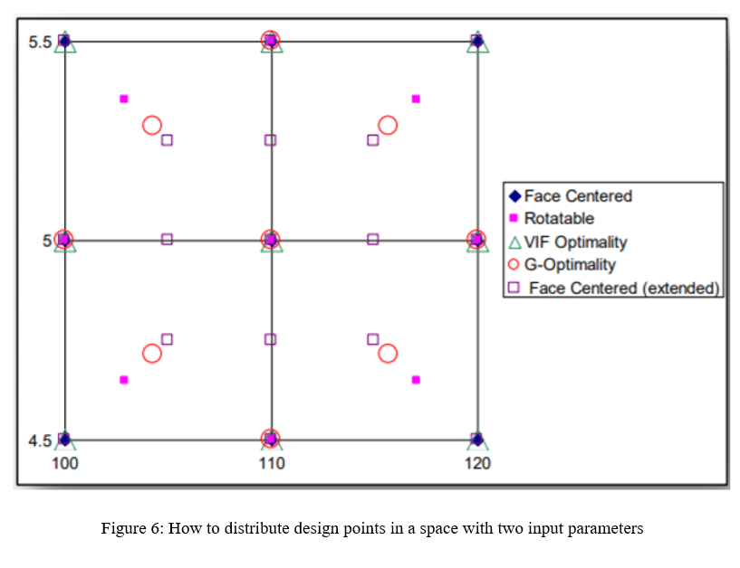
In auto-defined mode, the software automatically selects the most suitable CCD model according to the number of variables or input parameters. Usually between G-optimality and VIF- optimality. We recommend to use the same mode of automatic software selection. Users should rotatable mode. When divided values of the input parameters do not fit well with the graph of the response surface. Figure 16 shows a space for design points for a model with two input parameters. The design points are located simultaneously based on different patterns of the central composite (CCD) method. These patterns include face-centered, rotatable, variance inflation optimization (VIF-optimality), and G-optimality. Using this image, you can compare the distribution of design points in a two-parameter space.
 As An Main Doe Method 20")
Figure 16. How to Distribute Design Points in a Space With Two Input Parameters.
Related Posts

CFD Project Outsourcing: What Files, Reports, and Results Should You Expect?
When engineering teams decide to outsource CFD simulation, the conversation almost always starts with capability and…

ANSYS Fluent Consulting: Get Defensible, Audit-Ready Simulation Results
You need ANSYS Fluent results that can survive scrutiny — a design review, a client…

CFD Simulation Services for Product Design: Reduce Prototyping Cost Before Manufacturing
In modern product development, the most expensive mistakes are often discovered after money has already…
Comments (0)