
ANSYS STRUCTURAL: Connecting Rod Static Simulation
$180.00 Internship
- This product simulates a Connecting Rod using ANSYS Static Structural software.
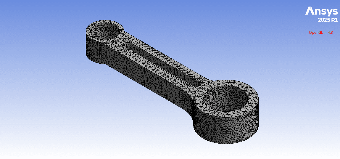
- We model the 3D geometry with the Design Modeler software and mesh it as an unstructured grid.
- We use Fixed Support and Force Load as the boundary load conditions.
To Order Your Project or benefit from a CFD consultation, contact our experts via email (info@mr-cfd.com), online support tab, or WhatsApp at +44 7443 197273.
There are some Free Products to check our service quality.
If you want the training video in another language instead of English, ask it via info@mr-cfd.com after you buy the product.
Description
ANSYS Static Structural: Connecting Rod Analysis under Force Load and Fixed Support
Description
In this project, we present a structural simulation of a Connecting Rod in ANSYS Static Structural.
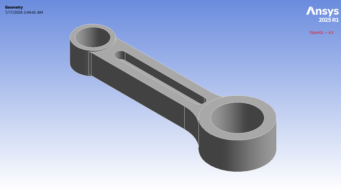
A connecting rod is the component that transmits motion and force between the piston and the crankshaft in internal combustion engines, compressors, and other machinery. In other words, it converts the linear motion of the piston into the rotary motion of the crankshaft.
These connecting rods are classified by their cross-section into different types, including I-beam rods and rectangular rods. For the present study, a connecting rod with the I-beam type is modeled. This is the most typical, containing the best strength-to-weight ratio.
Since the connecting rod is one of the most highly loaded components in an engine system, structural analysis of it is important. So, this simulation aims to evaluate the stress and deformation in the connecting rod body under applied load.
Methodology
First, we modeled the connecting rod geometry using Design Modeler software. The computational domain corresponds to a single connecting rod, which joins two rod ends (small and large ends). Second, we meshed the domain. As a result, an unstructured mesh was created, generating about 20,000 elements. Finally, we completed the simulation and calculations with ANSYS Static Structural software.
Note that the larger end hole is the bearing rod, which wraps around the crankpin journal of the crankshaft; while the smaller end hole is the bushing rod, which receives the wrist pin that connects the rod to the piston. So, the connecting rod is to carry the axial force between the two ends.
We considered that the large end is clamped by the bolts tightly around the crankpin. So, we defined a fixed support to the inner surface of this big end, constraining all degrees of freedom.
However, we assumed a force load is applied to the inner surface of the small end. It represents the force delivered by the wrist pin that presses into the bore. So, we defined a force load on the inner surface of this small end as the load boundary condition. For this, we specified the force value by X and Z components (meaning the force is in a certain angular direction). Since the Y-axis of the bore is parallel to the crankshaft’s axis of rotation, no force is applied to the connecting rod along it. Meanwhile, dividing the load into X- and Z-components gives the rod’s deflection (except at top and bottom dead center, the connecting rod is deflected relative to the cylinder axis at an angle determined by the crankshaft position).
Conclusion
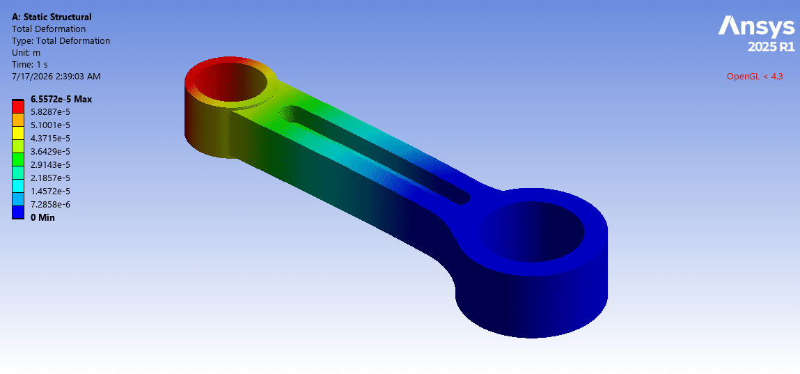
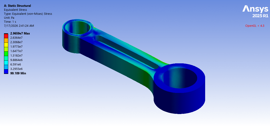
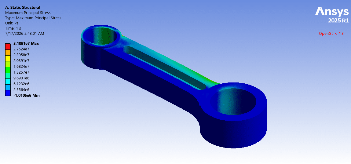
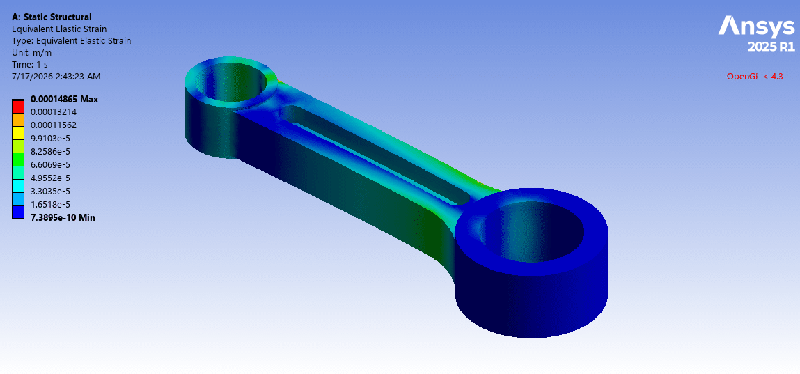
After the calculations, we obtained the contours of total deformation, equivalent strain, and equivalent (von Mises) stress over the connecting rod.
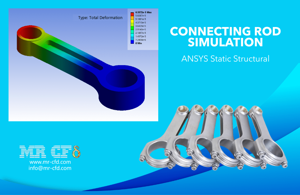
The total deformation distribution shows that maximum deflection occurs at the small end, where it is farthest from the constrained big end. So, the small end undergoes the force in specified directions while the big end remains stationary. This result is fully consistent with a component loaded at one end and restrained at the other.
The stress distribution indicates that the higher stress appears at the fillets where the rods connect to the two ends and around the inner surface of the small end hole.
You must be logged in to post a review.

 Talk On WhatsApp
Reviews
There are no reviews yet.