
ANSYS STRUCTURAL: Dam, Comparative Static Analysis
$270.00 Internship
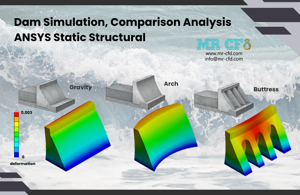
- This product simulates a Dam using ANSYS Static Structural software.
- We study the dam with three configurations in different cases (Gravity, Arch, Buttress) based on a comparison analysis.
- We model the 3D geometry with the Design Modeler software and mesh it as an unstructured grid.
- We use Fixed Support, Earth Gravity, and Hydrostatic Pressure Load as the load boundary conditions.
To Order Your Project or benefit from a CFD consultation, contact our experts via email (info@mr-cfd.com), online support tab, or WhatsApp at +44 7443 197273.
There are some Free Products to check our service quality.
If you want the training video in another language instead of English, ask it via info@mr-cfd.com after you buy the product.
Description
ANSYS Static Structural: Dam Comparison Analysis under Pressure Load, Standard Earth Gravity, and Fixed Support
Description
In this project, we present a structural simulation of a Dam in ANSYS Static Structural. This product is a comparative structural analysis involving three dam types.
A dam is a structural barrier built across a river to retain water behind it, raise the water level, and store water resources. These dam systems are designed for purposes such as water supply, flood control, and hydroelectric power generation. The main task of this civil-engineering structure is to resist the enormous horizontal push of the water.
Dams are classified into three principal types. So, for the present study, we investigate all three types to achieve a comparison analysis:
- Gravity-type dam
- Arch-type dam
- Buttress-type dam
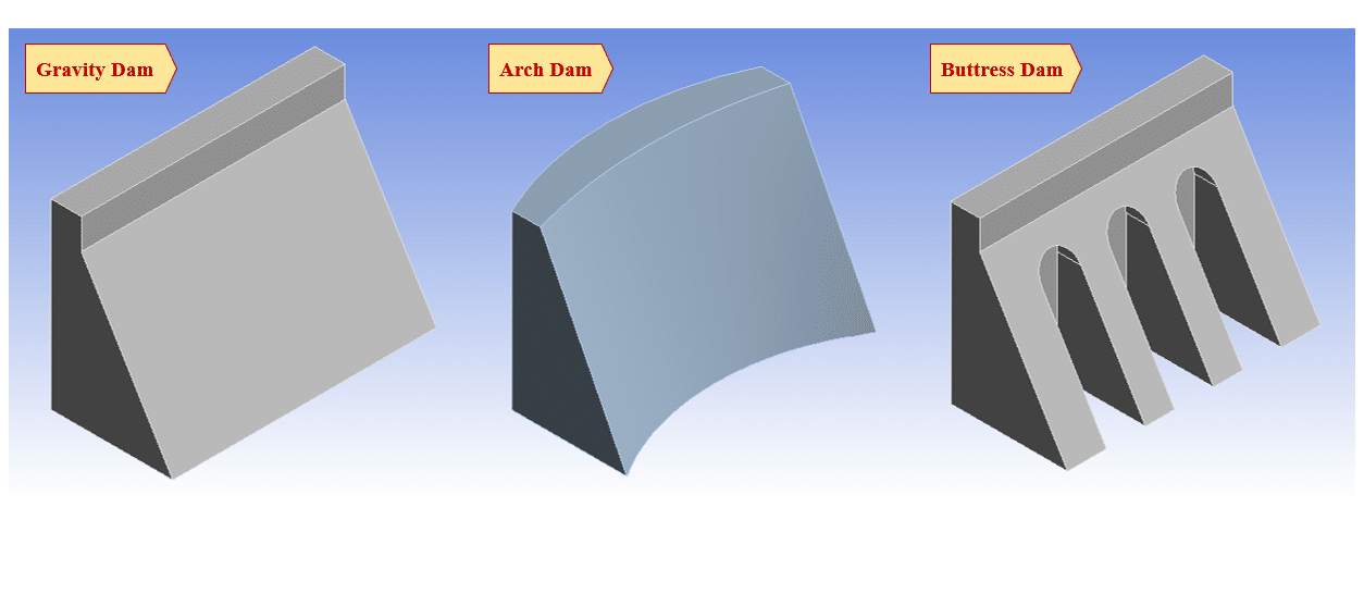
A gravity dam is a large solid block with a typically triangular section. It resists the water load purely through its own massive weight, and because of self-weight and the friction at its base, is prevented from sliding or overturning. An arch dam has a curved plan so that it operates like a horizontal arch. It transfers the water load sideways into the two walls as the abutments. A buttress dam holds a relatively thin water-facing wall that is propped up from behind by a series of buttresses as the supports. So, the existing spaces between the buttresses save a large amount of required materials in the construction.
The goal of this study is to analyze the dam operating mechanism in three separate cases. The front edge distance is the same in all three configurations until reaching a fair comparison. The first case (i.e., gravity-type) consists of a flat face in contact with the water and a fully uniform solid body. The second case (i.e., arch-type) differs from the first in that its water-facing wall is curved instead of flat. The third case (i.e., buttress-type) has the same water-contact face, but differs in the arrangement of its solid body. Its body contains empty spaces, operating as a supporting wall braced by the buttresses.
Methodology
First, we modeled the geometry of the dam with Design Modeler software. The computational domain is different in the three cases. The gravity dam is constructed of a solid flat-faced block, the arch dam is of a curved-face body, and the buttress dam is of a braced wall with void spaces.
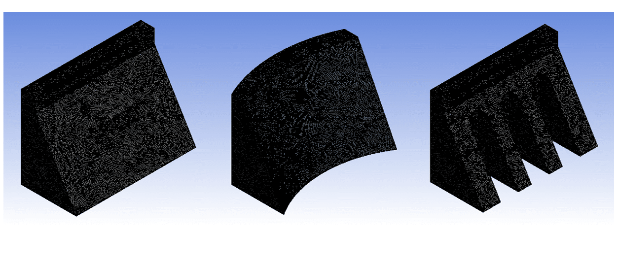
Second, we meshed the domain for all three cases. As a result, an unstructured mesh was created, generating about 317000, 530000, and 381000 elements, respectively. Finally, we completed the simulation and calculations for all three cases with ANSYS Static Structural software.
For all three cases, we defined identical loads and constraints. We considered the bottom face of the dam blocks to be completely constrained with no degree of freedom. So, we defined a fixed support on the bottom base of each dam. Also, we defined standard Earth gravity as a load boundary condition over the whole body of all dams. This load is applied downward on the entire dam body to represent self-weight.
The main step is to define the load boundary condition. We considered that the water load is applied to that face of the dam in contact with the water flow. So, we used a hydrostatic pressure boundary condition on the water-facing side. It is specified through the water density and the gravity direction, so that the pressure grows linearly with water depth (zero at the water surface and maximum at the base).
Conclusion
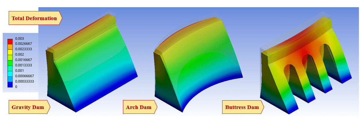
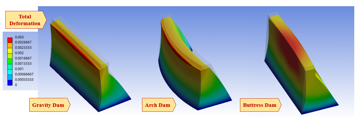
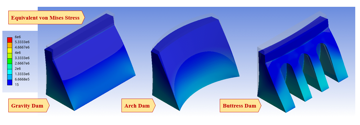
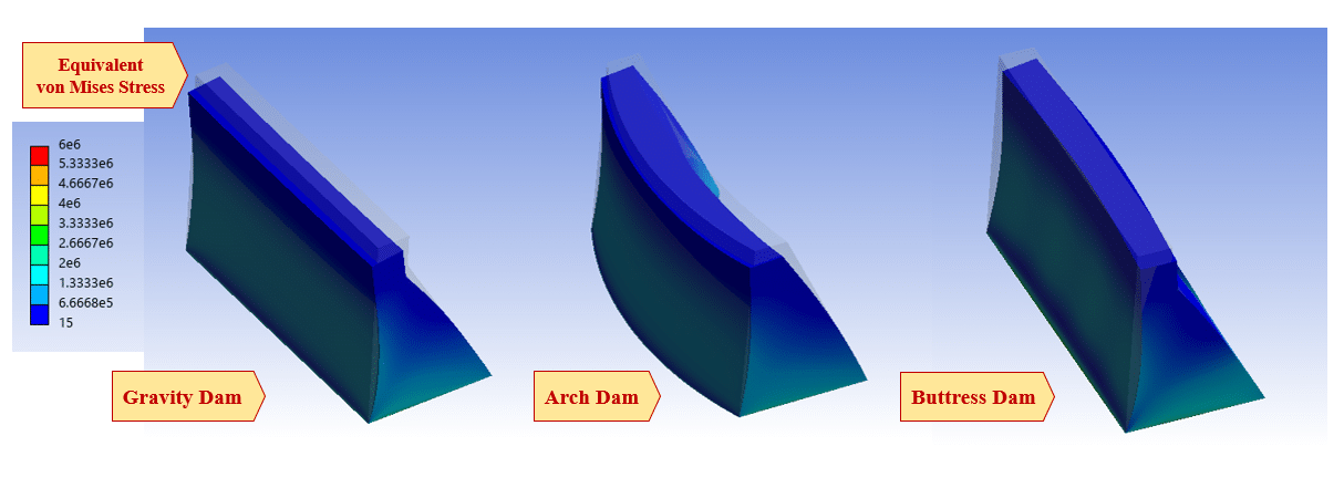
After the calculations, we obtained the contours of total deformation and equivalent (von Mises) stress over the dam bodies. We studied the deformation and stress distributions on all three types of dam to achieve a comparative analysis
In every case, the maximum deflection occurs on the top regions of the dam block, which is farthest from the fixed base. These dam bodies are pushed in the downstream direction by the water pressure, while they stay stationary at the base.
In every case, the maximum stress appears near the bottom fixed support, because the combination of the water’s hydrostatic pressure and the dam’s weight produces the largest moment adjacent to those regions.
In the comparative approach, the gravity-type dam carries the load through only its bulk weight, showing well-distributed stresses and small deflections, at the cost of using the most materials; the arch dam, because of its curved face, transfers a portion of the water load sideways rather than resisting it by bending alone, so it can be constructed more slender with the least materials; the buttress dam concentrates the pressure load into its legs and carry the load down to the base, so that it needs much less material than other dam types, but with higher local stresses at the wall-to-buttress connections.
You must be logged in to post a review.

 Talk On WhatsApp
Reviews
There are no reviews yet.