Windcatcher CFD Simulation ANSYS Fluent Training
$60.00 Student Discount
- In this project, we have simulated a Windcatcher using ANSYS Fluent software as a Passive Ventilation system.
- Three-dimensional windcatcher modeling was done using Design Modeler software.
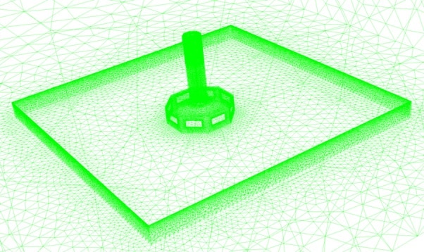
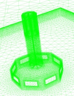
- The model meshing has been done using ANSYS Meshing software, and the element number is 2332185.
To Order Your Project or benefit from a CFD consultation, contact our experts via email ([email protected]), online support tab, or WhatsApp at +44 7443 197273.
There are some Free Products to check our service quality.
If you want the training video in another language instead of English, ask it via [email protected] after you buy the product.
Description
Description
This simulation is about windcatcher via ANSYS Fluent software. We perform this CFD project and investigate it by CFD analysis. The Wind Catcher transfers air into the building by suction to drive warm and polluted air out. The internal structure is such that air enters and traps between the walls. As a result, air moves downward from its outlet panels to the building’s interior.
A windcatcher is a tower for ventilation and cooling the building’s interior located on the roof. These windcatchers are usually tall, and engineers build them in the form of one-way, four-way, and eight-way. The mechanism of the windcatcher is to take the desired wind from the ambient to the building.
Sometimes, inside the buildings, there are special pools through which the wind flows and cools down by evaporation, resulting in moist and cool winds.
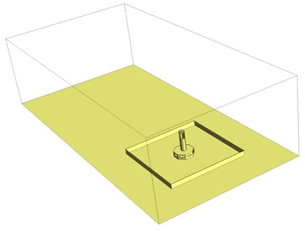
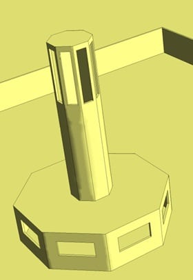
This problem is to simulate the airflow and ventilation inside a windcatcher. The windcatcher is octagonal and has a relatively simple structure. The windcatcher consists of a column for pulling the out air to the inside or sucking up the air inside, room space for air circulation inside it, and a wall for the space around the building of this windcatcher also.
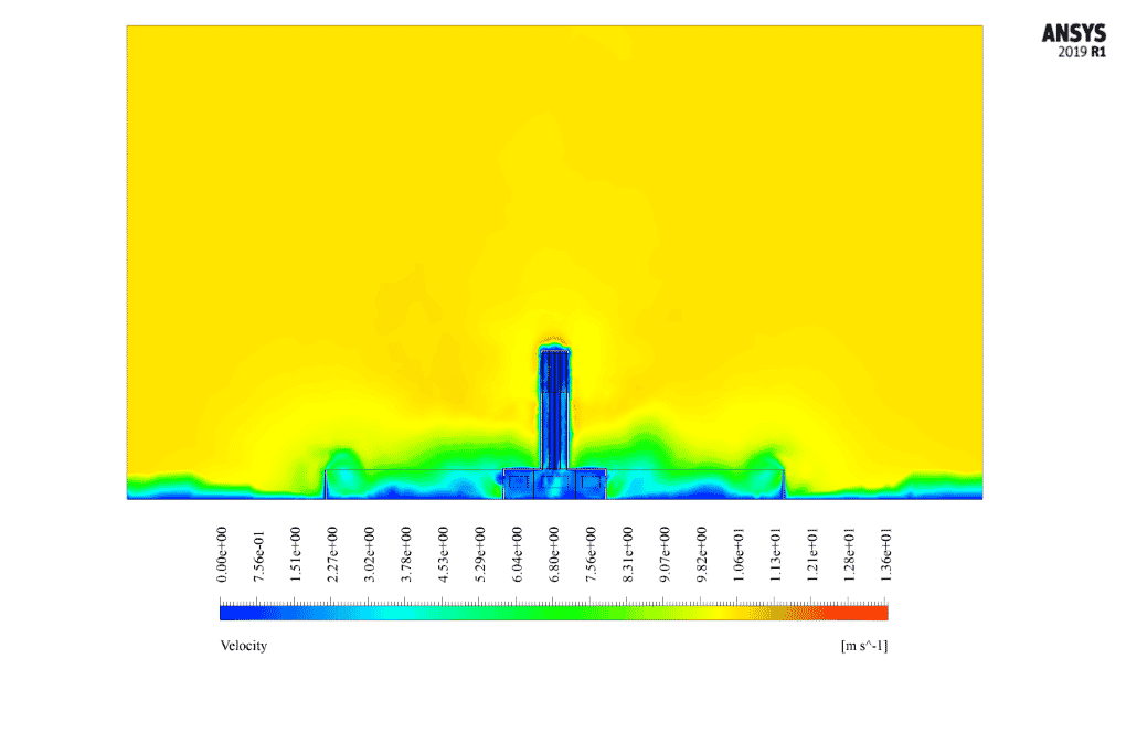
This windcatcher set is located in a large space of open airflow domain. The wind moves horizontally at 10 m/s towards the windbreak building. Also, the model pressure is equal to atmospheric pressure.
This project investigates the flow of air entering the windcatcher building and the flow of air inside it.
We have designed the geometry using ANSYS Design modeler software. We also created the mesh on this geometry using ANSYS meshing software. The mesh type is unstructured with 2332185 cells.
Method
We only discuss fluids analysis in this simulation and don’t require heat transfer analysis. In this project, geometric modeling is important for fluid behavior.
In the interior space above the windcatcher, we design surfaces as barriers in such a way that some windcatcher inlets are exposed to direct wind flow; In this way, traction and the suction property are created inside the windcatcher on both sides of the windshield column, and thus the circulation of airflow inside the interior of the room below the windcatcher.
Windcatcher Result
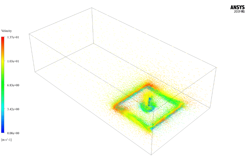
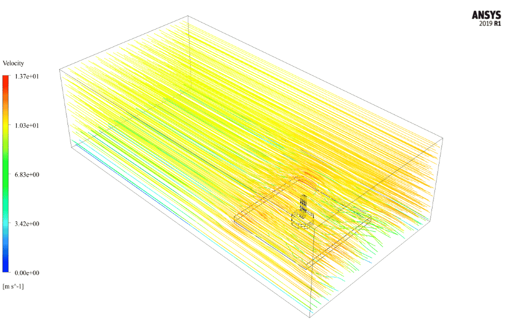
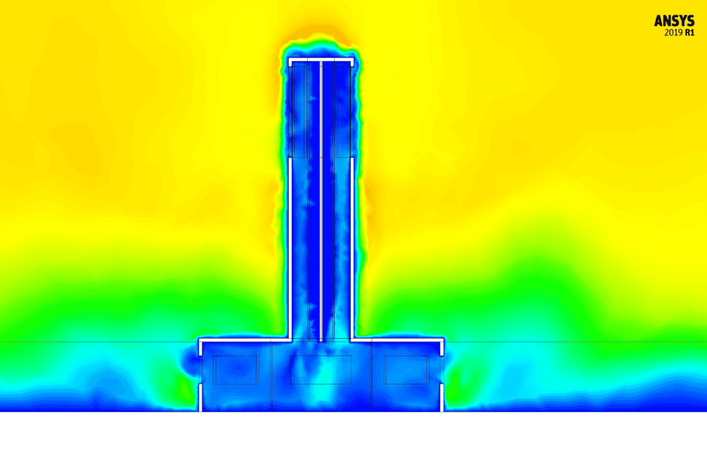
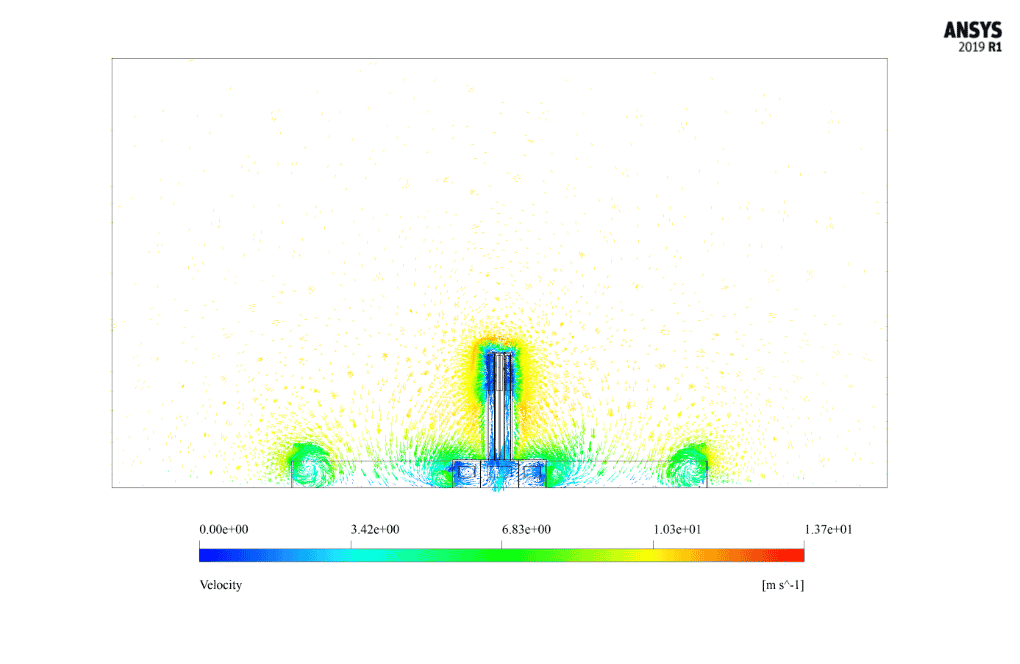
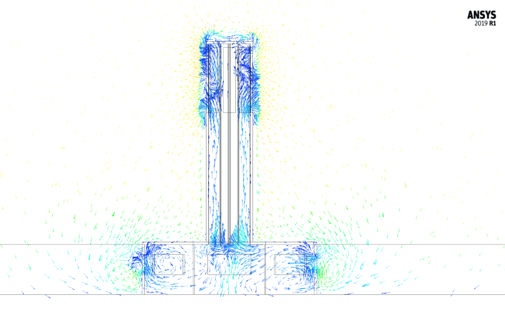
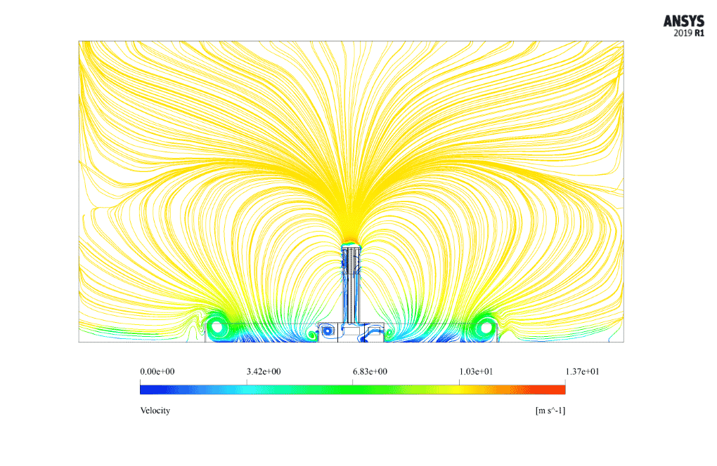
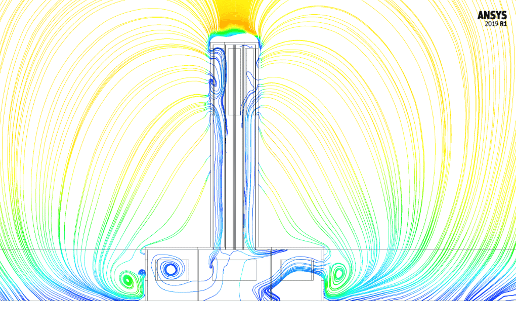
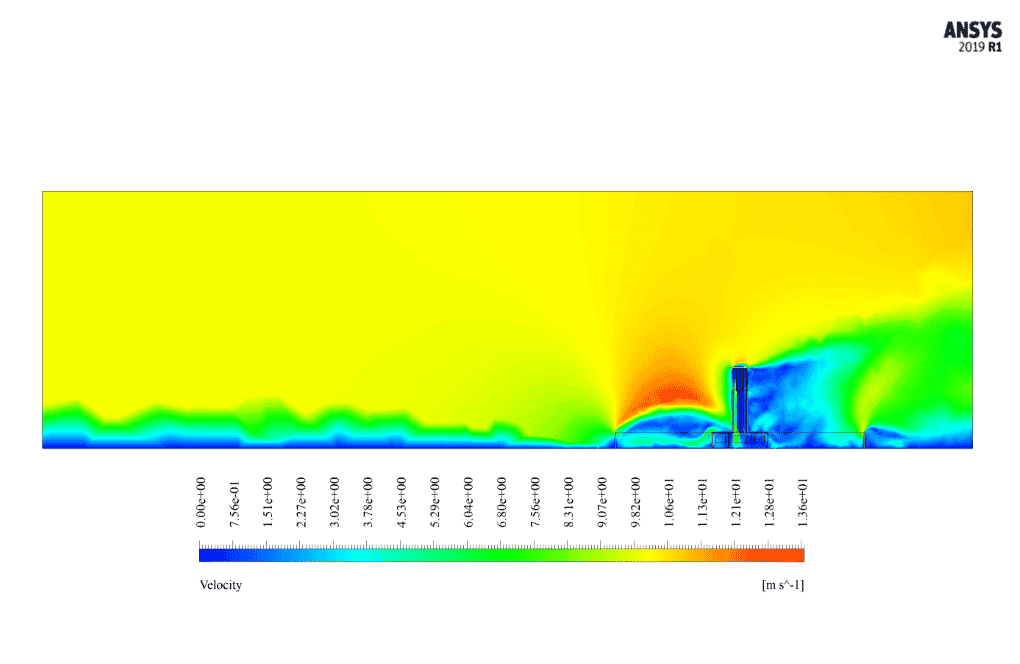
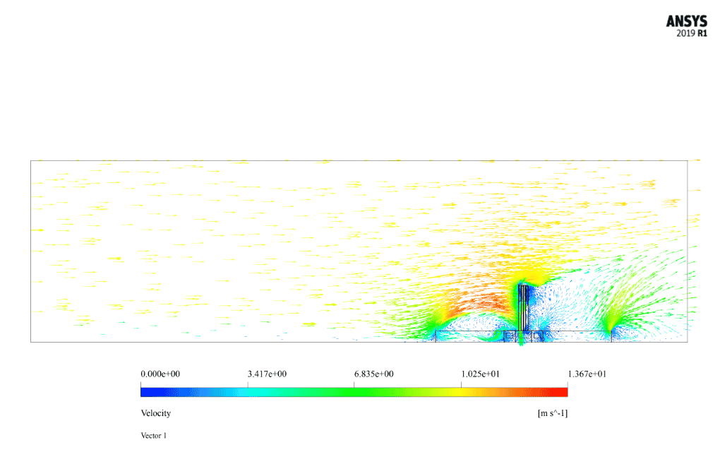
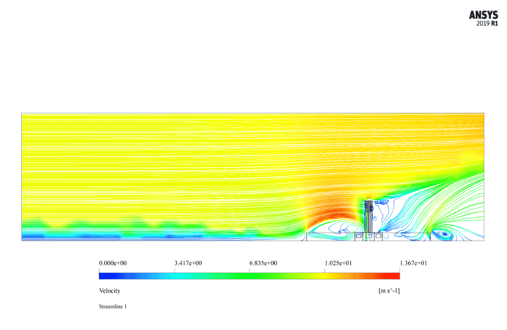
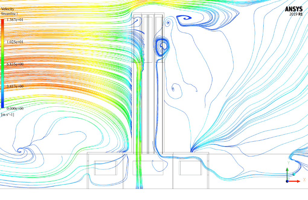
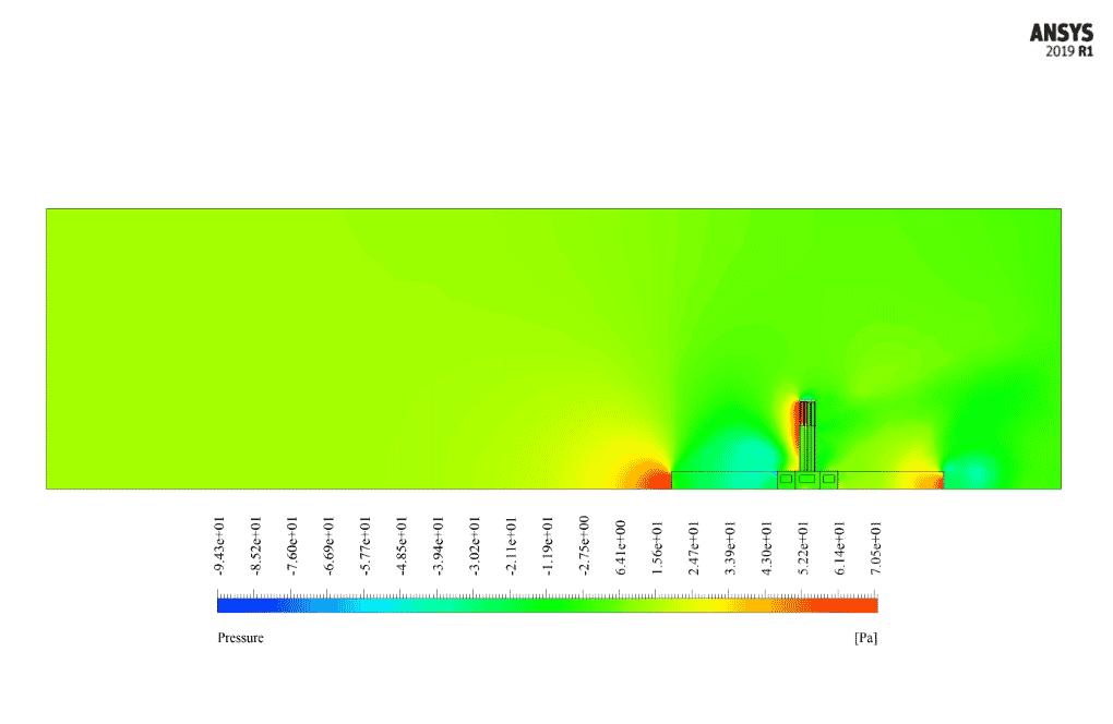
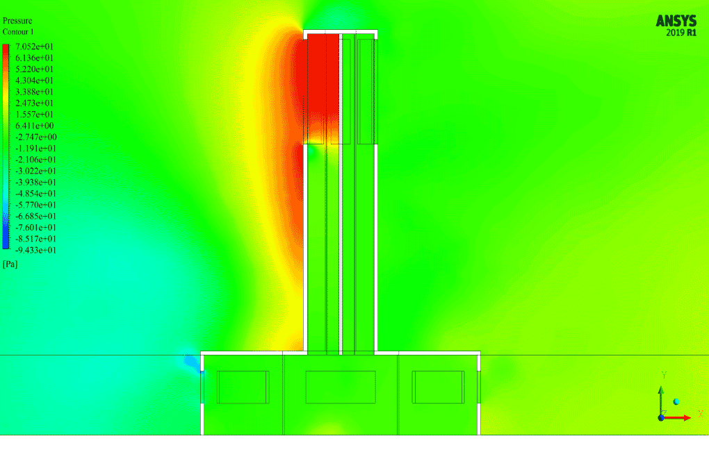
After simulation, we obtain the contours of velocity and pressure. Also, we obtain velocity vectors and pathlines. The contours show that the pressure is greater in the part of the windcatcher in front of direct winds than in the part of the windcatcher behind the wind direction.
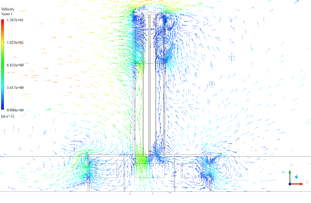
Also, the vectors and pathlines clearly show that the airflow enters from the top panels of the windshield tower and, after being trapped, moves downwards and is transferred from the lower panels of the windshield to the building’s interior. So, in conclusion, the system of this windshield is working properly.





Prof. Archibald Maggio –
excellent
Royal Blick –
This simulation sounds fascinating. Can you tell me if options for improving the windcatcher’s efficiency were explored during the simulation, such as modifications to its geometry or the addition of features?
MR CFD Support –
In this specific project, the current focus was on analyzing the airflow and ventilation within a traditional windcatcher design. However, exploring modification options for enhancing efficiency, like shape optimization or additional architectural features, can certainly be done in future simulations. These would include comparing different designs, analyzing their performance, and determining which modifications improve air circulation and cooling effectiveness most significantly.
Adriel Schneider IV –
I’ve always been fascinated by the fusion of traditional design and modern technology in windcatchers. The simulation you described seems thorough, indicating a higher effectiveness of these amazing structures. The ability of the windcatcher to induce ventilation without the need for mechanical systems never ceases to impress me!
MR CFD Support –
Thank you so much for your kind words! Indeed, the remarkable efficiency of traditional windcatchers, now validated and optimized by modern CFD simulation, holds timeless appeal. Their sustainable operation that leverages natural ventilation continues to offer valuable lessons in design. We’re glad you found our simulation training on ANSYS Fluent informative and helpful.
Dr. Katrina Muller DVM –
I’m amazed at how this technology works for ventilation and cooling! Great simulation study on windcatchers.
MR CFD Support –
Thank you for your appreciation! We’re delighted that you found the simulation study informative and that you recognize the efficiency of windcatcher systems in natural ventilation and cooling solutions. If you have any more thoughts or need further details, feel free to reach out.
Dallin Boyer –
I’m interested in your wind catcher simulation. Can you tell me more about the principles and phenomena it’s based on?
MR CFD Support –
Of course! Our wind catcher simulation is based on the principles of fluid dynamics. It simulates the flow of air within a wind catcher, which is a traditional architectural element used for creating natural ventilation in buildings. The simulation allows us to study how different factors, such as wind speed and direction, affect the performance of the wind catcher.
Linda Crooks –
The Windcatcher CFD Simulation by ANSYS Fluent is absolutely fascinating! It’s incredible to see the airflow patterns and how the device creates a natural ventilation effect. This would be incredibly useful for sustainable building designs.
MR CFD Support –
Thank you for your positive feedback on our Windcatcher CFD Simulation training! We are glad that you appreciate the intricate details of airflow patterns and the application for sustainable design. It’s always rewarding to hear from satisfied learners, and we’re delighted that our product could contribute to your understanding of natural ventilation systems in buildings.
Ms. Aurelia Bogan II –
I’m thoroughly impressed with the level of detail included in the Windcatcher CFD simulation training. It perfectly demonstrated the airflow and ventilation mechanics achieved by the windcatcher—a brilliant tool for understanding such complex dynamics.
MR CFD Support –
Thank you for your positive feedback! We’re thrilled to know that the Windcatcher CFD simulation training provided the needed clarity and insight into airflow and ventilation. Our aim is always to deliver comprehensive and detailed educational content. Your satisfaction is a great affirmation for the work we do.
Mr. Everett Torphy I –
The quality of your simulations is top-notch! Keep up the good work
MR CFD Support –
Thank you for the compliment! We will continue to strive for excellence in all our simulations.
Cary Medhurst –
The training is well-explained with comprehensive results from the simulation. It demonstrates the effectiveness of the windcatcher in real-world applications, which is crucial for sustainable building design. Well done!
MR CFD Support –
Thank you so much for your kind words! We’re thrilled to hear that you found the Windcatcher CFD Simulation ANSYS Fluent training helpful and educational. Your feedback is greatly appreciated, and we’re glad we could assist in your understanding of sustainable building ventilation systems.
Reuben Turner IV –
I’m very impressed with the level of detail in the Windcatcher CFD Simulation training. The understanding of air movement within the structure is quite fascinating. The practical application of this is evident in creating more efficient and environmentally-friendly cooling systems for buildings. Keep up the excellent work!
MR CFD Support –
Thank you for your kind words and appreciation. It’s great to hear that our Windcatcher CFD Simulation training was insightful and informative for you. Our goal is to provide high-quality learning experiences that are both practical and beneficial for environmental sustainability. If you have further interests or questions, we are always here to help!
Miss Agustina Braun –
I’m impressed with the precision of this simulation! Can this analysis help specify the best windcatcher design to implement in a certain geographic area with existing wind patterns?
MR CFD Support –
Thanks for your kind words! This CFD analysis can indeed be a useful tool in determining the optimal design of a windcatcher by assessing different configurations under simulated wind conditions that resemble those of a specific geographic area. By analyzing the airflow patterns, velocity distribution, and pressure differentials, engineers can optimize the windcatcher’s performance for local environmental conditions, addressing factors such as prevailing wind directions and intensities.
Ian Corwin –
The simulation study sounds fascinating; I’m curious how the presence of wind direction adjustments is taken into account. Does the simulation dynamically change based on variable wind directions or is it only set for a single, constant direction?
MR CFD Support –
In this particular simulation, the wind direction is set to a constant, where the wind is moving horizontally towards the windcatcher at a velocity of 10 m/s. However, it is possible to perform additional studies with variable wind directions in order to assess the windcatcher’s performance under different environmental conditions. Multipoint or dynamic boundary conditions could be applied in these instances to simulate changing wind directions and study their effects.
Shanna Zboncak –
I’m thoroughly impressed with the tangible application of CFD in simulating the windcatcher performance. The idea of utilizing wind to naturally ventilate and cool interiors is ingenious, and the fact that you could effectively model this with ANSYS Fluent is commendable.
MR CFD Support –
Thank you so much for your kind compliments! We’re delighted to hear that our simulation of the windcatcher performance met your expectations and that you recognize the innovative use of natural wind for ventilating and cooling building interiors. ANSYS Fluent’s capabilities are indeed extensive, and we’re glad the real-world applicability of the software was clearly demonstrated in our project. If you have any further feedback or require additional simulations, please let us know!
Giovanni Langosh I –
I really appreciated the detailed explanation of the airflow patterns in the Windcatcher CFD Simulation Training. The illustrations of pressure contours and airflow pathways provided a clear understanding of how windcatchers function to ventilate a building efficiently.
MR CFD Support –
Thank you for taking the time to review our Windcatcher CFD Simulation training product. We’re glad to hear that the explanations and visual aids were helpful and provided you with a clear understanding of the windcatcher’s operational mechanics. We always strive to deliver comprehensive learning materials to our users. Your positive feedback is greatly appreciated!
Dr. Abigale Becker PhD –
I am really happy with the detailed analysis and results shown for the Windcatcher CFD Simulation. The velocity and pressure contours were clear and the illustrations of the airflow pathway through the windcatcher were very informative. The training made the concept and function of a windcatcher easy to understand!
MR CFD Support –
Thank you for your kind words! We’re delighted to hear that the Windcatcher CFD Simulation has been informative and helpful in understanding the airflow mechanism. If you’re interested in exploring more CFD analysis topics or simulations, feel free to check out our other training products. Your satisfaction is our top priority!