
ANSYS Static STRUCTURAL: Twisted Beam Simulation, Paper Validation
$495.00 Internship
- This product simulates a Twisted Beam using ANSYS Static Structural software.
- We model the 3D geometry using the DesignModeler software and mesh it with a Structured grid.
- This project has been implemented in Four Cases: no twist / with a 180-degree twist and lengths of 350 mm / 700 mm.
- We use Fixed Support and Force Load as the load boundary conditions.
- We represent a Paper Validation with a reference Article.
To Order Your Project or benefit from a CFD consultation, contact our experts via email (info@mr-cfd.com), online support tab, or WhatsApp at +44 7443 197273.
There are some Free Products to check our service quality.
If you want the training video in another language instead of English, ask it via info@mr-cfd.com after you buy the product.
Description
ANSYS Static Structural: Twisted Beam Analysis and Paper Validation (under Force Load and Fixed Support)
Description
In this project, we present a structural simulation of a Twisted Beam in ANSYS Static Structural.
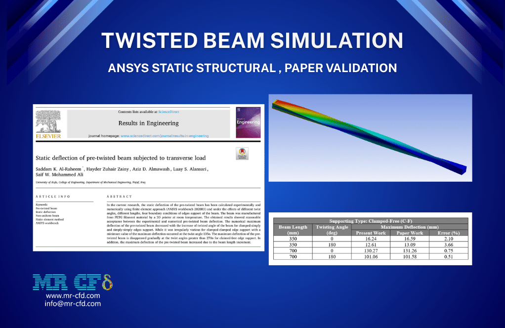
This product is provided based on the numerical simulation of a reference article, “Static deflection of pre-twisted beam subjected to transverse load”. Then, the results of the present work are compared and validated with the reference article.
According to the reference paper, a simple long beam is modeled. This beam has been analyzed in various conditions and configurations, and the static behavior of the pre-twisted beam has been evaluated under the effects of these:
- Different lengths for the beam: from 350 to 700 mm
- Different twisting angles: from 0 to 540
- Different supporting types: clamped-free/clamped-clamped/clamped-simply/simply-simply
For this investigation, we only performed a simulation of the beam with clamped-free support. Then, we performed the run calculation in four cases: two different lengths of the beam (350 and 700 mm) and two different twist angles (0 (no twist) and 180 degrees).
So, the goal of this study is to calculate the static deflection of the beam under different cases.
Methodology
We prepared four cases for simulation in ANSYS Statics Structural.
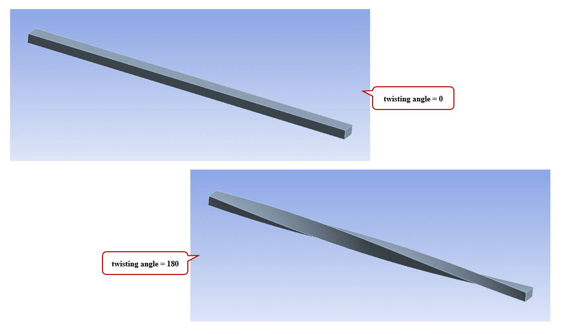
Therefore, we modeled the geometry of the beam with Design Modeler software. The computational domain corresponds to a simple beam with a rectangular cross-section. Since we intend to examine four different cases, we modeled four different geometries: 1. 350 mm length with no twist, 2. 350 mm length with 180 twisting angle, 3. 700 mm length with no twist, and 4. 700 mm length with 180 twisting angle.
Then, we meshed the domain in all cases. Because of the uniform and symmetrical construction of the beam, a structured mesh was created. Finally, we completed the simulation and calculations for each case with ANSYS Static Structural software.
As the material for this beam, the PETG (Polyethylene Terephthalate Glycol-Modified) is determined.
We considered that the horizontal beam is completely constrained at the first face (without any free movement), while a continuous transverse load is applied to the end face of the beam. Therefore, for the load boundary conditions, we used a fixed support for the first face and a force load on the end face of the beam. This force load is defined as 3 N in the downward direction.
Conclusion
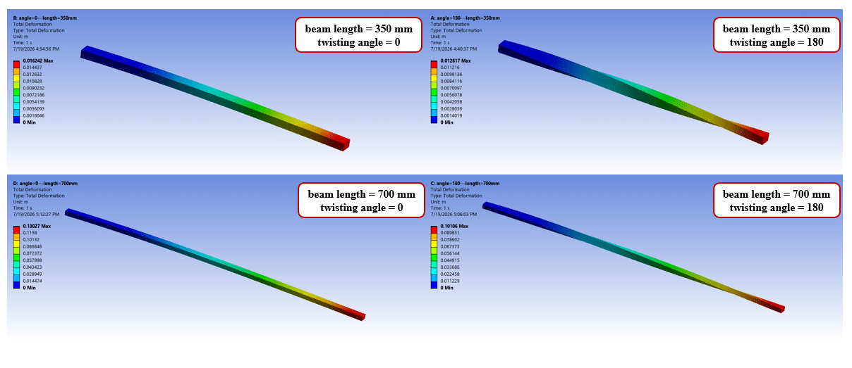
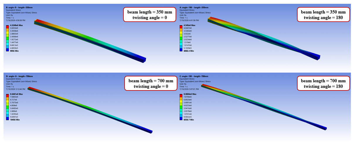
After the calculations, we obtained the contours of total deformation and equivalent (von Mises) stress over the beam. These distributions of the deformation and the stress are obtained for all four cases.
The total deformation distribution shows that maximum deflection occurs at the end face of the beam, where the force load is applied and the highest distance from the constraint face. The stress distribution indicates that the maximum value appears near the fixed support, where the loading moment is highest. These results are fully consistent with the behavior of the beam loading.
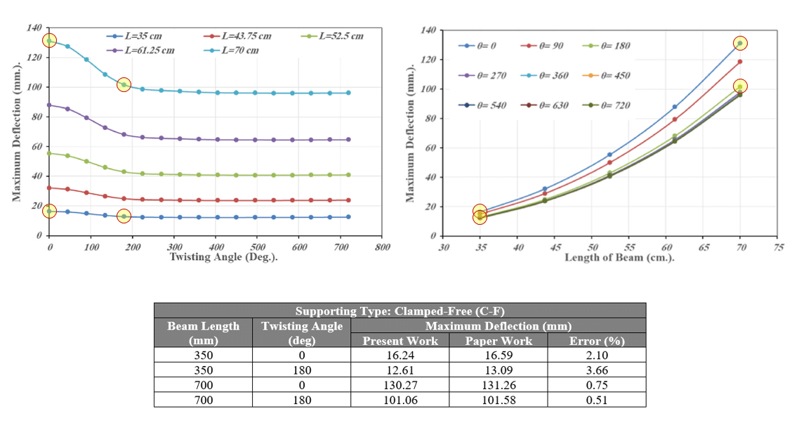
We performed a validation procedure for our numerical study based on one of the Maximum Deformations (Maximum Deflections) curves mentioned in the reference article. Therefore, we obtained the maximum deformation for all four cases. We compare these obtained deformation values with the values extracted from the deflection curves in the article.
A comparison of the results is provided in the table below. These results show that the present numerical work and paper validation procedure are highly accurate and precise. Comparison of the present work with the paper work confirms that the accuracy of the results is very high and the percentage of deviation is very low.
The average error is approximately 1.75%, and the minimum error is 0.51% for the case containing 700 mm length and 180-degree twisting angle, and the maximum error is 3.66% for the case containing 350 mm length and 180-degree twisting angle.
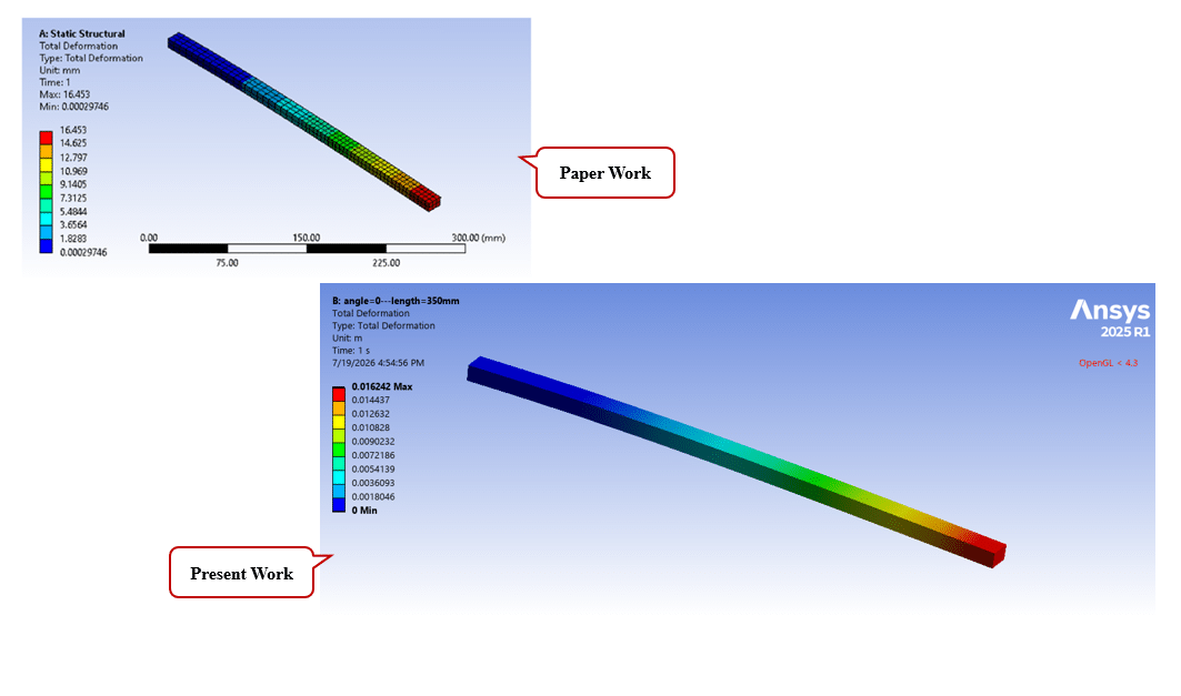
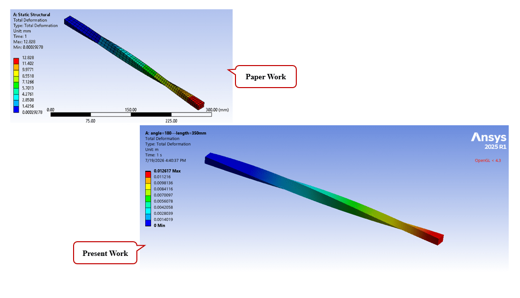
For greater assurance, we compared the contours related to the distribution of the total deformation for the no-twist and 180-degree twist cases with the contours presented in the paper. The results again confirmed that our simulation is performed with high accuracy.
You must be logged in to post a review.

 Talk On WhatsApp
Reviews
There are no reviews yet.