
ANSYS STRUCTURAL: Globe Valve Static Simulation
$180.00 Internship
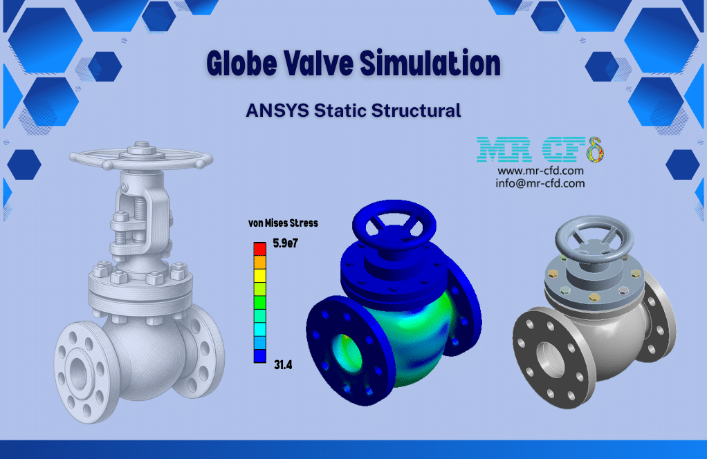
- This product simulates a Globe Valve using ANSYS Static Structural software.
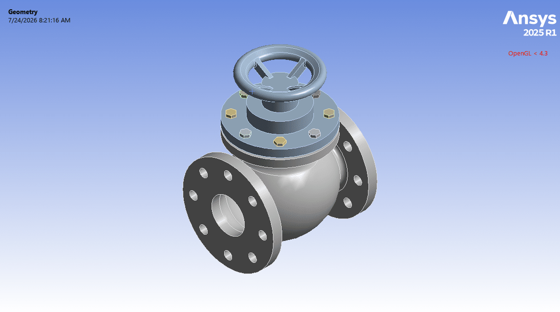
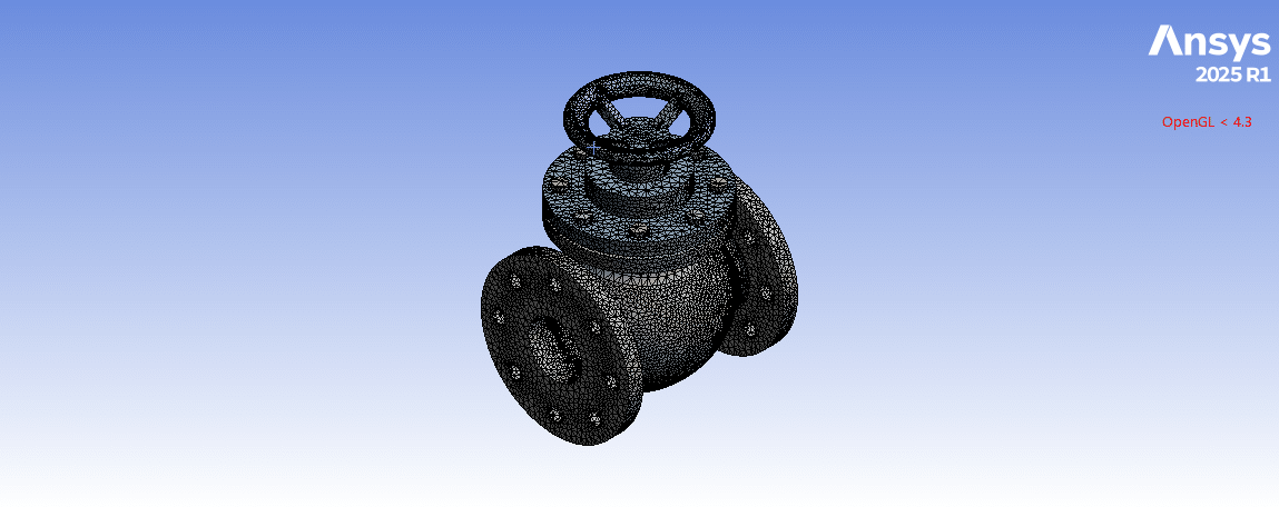
- We model the 3D geometry with the Design Modeler software and mesh it as an unstructured grid.
- We use Frictionless Support and Pressure Load as the load boundary conditions.
To Order Your Project or benefit from a CFD consultation, contact our experts via email (info@mr-cfd.com), online support tab, or WhatsApp at +44 7443 197273.
There are some Free Products to check our service quality.
If you want the training video in another language instead of English, ask it via info@mr-cfd.com after you buy the product.
Description
ANSYS Static Structural: Globe Valve Analysis under Pressure Load and Frictionless Support
Description
In this project, we present a structural simulation of a Globe Valve in ANSYS Static Structural.
A valve is a device used to control and regulate fluid flow or open/close the fluid flow in a piping system. The valves are classified based on their operating principle into different types, such as ball valves, globe valves, gate valves, butterfly valves, and check valves.
For the present study, a globe valve is modeled. The globe valve is one of the most widely used types in industrial plants, power stations, water facilities, and others. The globe valve operates by moving a disc against a fixed seat, which enables it to open and close the fluid flow, or regulate its mass flow rate.
The goal of this study is to analyze the structural behavior of the valve body under the design pressure by deformation and stress distribution.
Methodology
First, we modeled the geometry of the globe valve with Design Modeler software. The computational domain corresponds to a globe valve body, consisting of a main path oriented left-to-right, with a branch rising vertically from its centre where the handwheel is mounted. All three ends (left, right, and top) contain flanges with bolt holes.
Second, we meshed the domain. As a result, an unstructured mesh was created, generating about 122,000 elements. Finally, we completed the simulation and calculations with ANSYS Static Structural software. As a material, stainless steel is used for the valve body.
It is assumed that the valve is fully closed, so that the disc seals the fluid path. Therefore, the entire internal faces of the valve body have undergone pressure due to the fluid flow. So, a uniform pressure load is applied to the internal surface of the main flow, indicating the fluid pressure flowing through the valve. For this purpose, we defined a pressure load condition on the inner wall of the valve.
However, we defined frictionless support as the boundary condition on both ends of the main line of the valve. It is applied on the outer faces of the circular flanges and on the inner surfaces of their bolt holes. These frictionless supports restrain displacement only in the direction normal to the face while allowing free longitudinal displacement along the axis. This means that the flanges prevent the valve bodies from being pushed outward, and the bolts prevent the holes from displacing radially, but they do not prevent the body from expanding or contracting freely in the flange as it is pressurized.
Conclusion
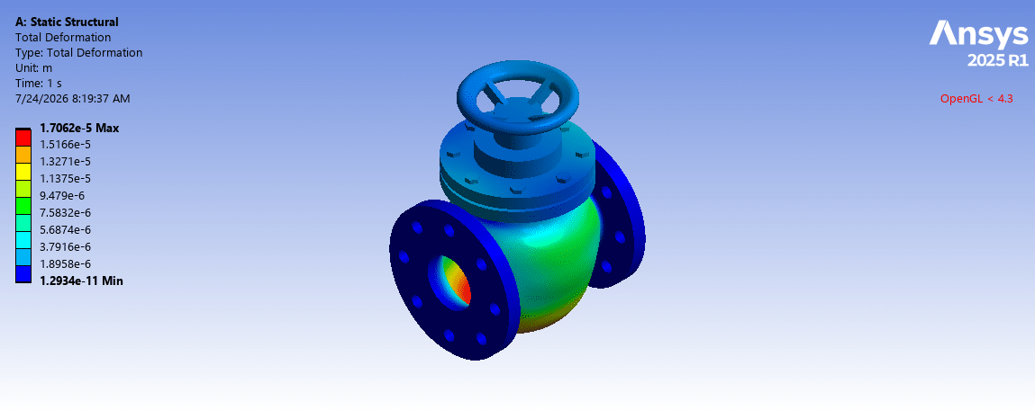
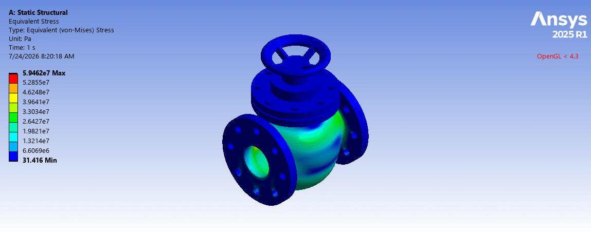
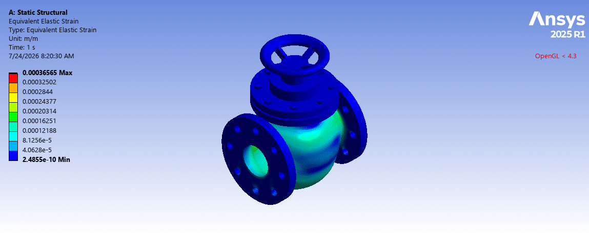
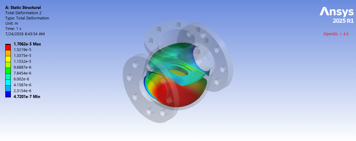
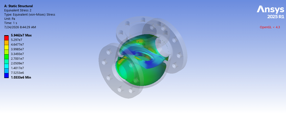
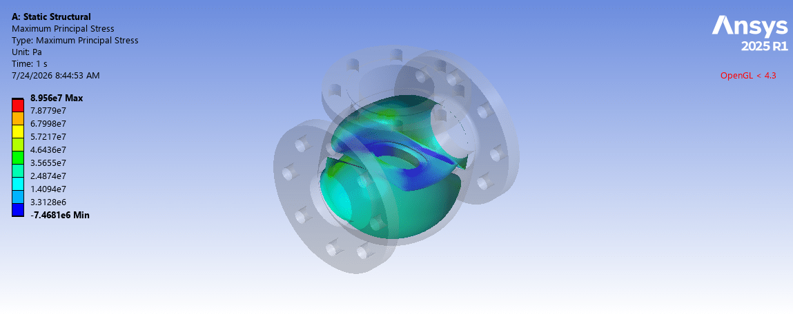
After the calculations, we obtained the contours of total deformation, equivalent strain, equivalent (von Mises) stress, and maximum principal stress. We displayed both the distribution over the entire valve body and throughout the inner wall of the valve from the main line.
The total deformation distribution shows that the highest deflection occurs in the middle regions of the globe valve. This is due to the hydraulic pressure of the fluid flow. This is while the flange surfaces and bolt holes are restrained in their normal directions.
However, the stress distribution indicates that the higher values appear near the vertical branch junction and adjacent to the bolted holes. In addition, high stress also occurs on the inner surface of the main line of the globe valve, since in a pressurized shell the stress increases at the inner wall of the valve.
You must be logged in to post a review.


 Talk On WhatsApp
Reviews
There are no reviews yet.