
ANSYS STRUCTURAL: Shaft and Bearing Assembly, Static Simulation
$180.00 Internship
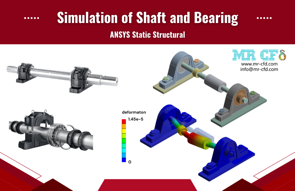
- This product simulates a Shaft and Bearing Assembly using ANSYS Static Structural software.
- We model the 3D geometry using the DesignModeler software and mesh it with an unstructured grid.
- We use Fixed Support, Standard Earth Gravity, and Force Load as the load boundary conditions.
To Order Your Project or benefit from a CFD consultation, contact our experts via email (info@mr-cfd.com), online support tab, or WhatsApp at +44 7443 197273.
There are some Free Products to check our service quality.
If you want the training video in another language instead of English, ask it via info@mr-cfd.com after you buy the product.
Description
ANSYS Static Structural: Shaft and Bearing Analysis under Force Load, Earth Gravity, and Fixed Support
Description
In this project, we present a structural simulation of the shaft and Bearing assembly in ANSYS Static Structural.
A shaft is a rotating machine element that transmits power and torque between components, while bearings are the supports that hold the shaft in place, control its loads, and allow it to rotate freely. The shaft-and-bearing assembly is one of the most common systems in rotating machinery, such as gearboxes, pumps, and conveyors.
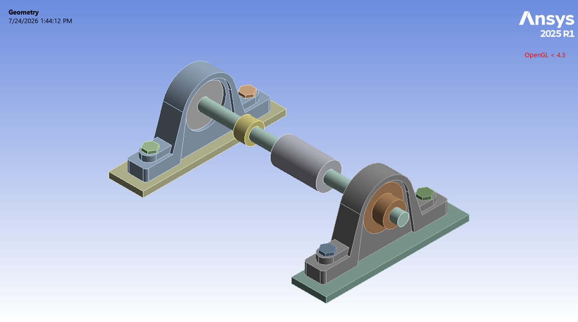
This assembly consists of a horizontal shaft supported at both ends by bearings and their housings and two pulleys mounted on the middle region of the shaft, through which belts drive or are driven by the shaft. Therefore, different types of loading can be imposed on the shaft and bearing assembly.
So, the goal of this study is to evaluate the structural behavior by deflection and stress distributions over the shaft and bearings under the combined loading. Also, this analysis is for capturing how such pulley loads are carried by the shaft and transferred into the bearing supports, so that the resulting bending can be examined.
Methodology
First, we modeled the geometry of the shaft and bearing with Design Modeler software. The computational domain corresponds to a shaft and bearing assembly. It consists of a principal horizontal cylindrical shaft containing two coaxial pulleys with different sizes, and constrained at two ends by the bearing/housing blocks.
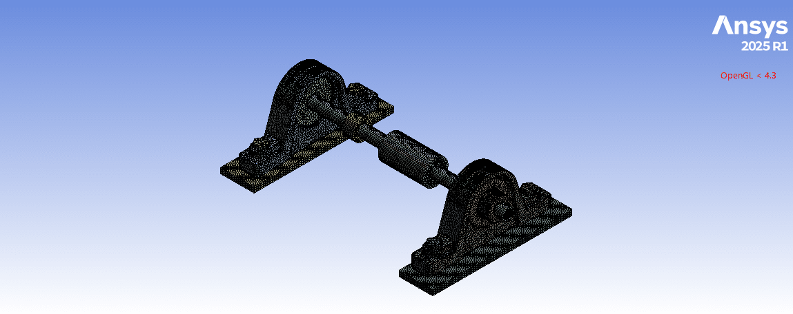
Second, we meshed the domain. As a result, an unstructured mesh was created, generating about 205,000 elements. Finally, we completed the simulation and calculations with ANSYS Static Structural software. For different parts in the construction of the shaft and bearing assembly, we defined various materials, including stainless steel, aluminum alloy, copper, structural steel, and gray cast iron.
We defined the load condition as standard Earth gravity applied downward to the entire body of the shaft-bearing system. This accounts for the weight of the shaft and the two pulleys mounted on it, because these relatively heavy pulleys impose a static bending load on the shaft. So, this load could not be ignored.
Next, we applied two force loads to the pulleys, with one lower force on the small pulley downward and one higher force on the large pulley horizontally. These loads indicate the tangential forces due to the driving pull of the belt that transmits torque.
Next, we defined the fixed support boundary condition for the bottom faces of the two supports under the bearing housings on both sides. These fixed supports represent the bearing being bolted down to a rigid frame, constraining all degrees of freedom.
Conclusion
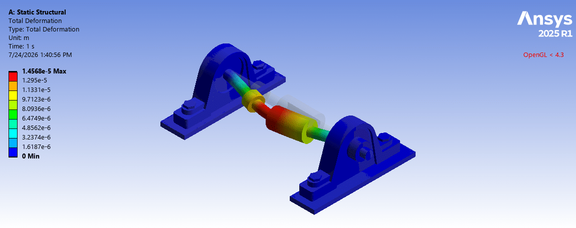
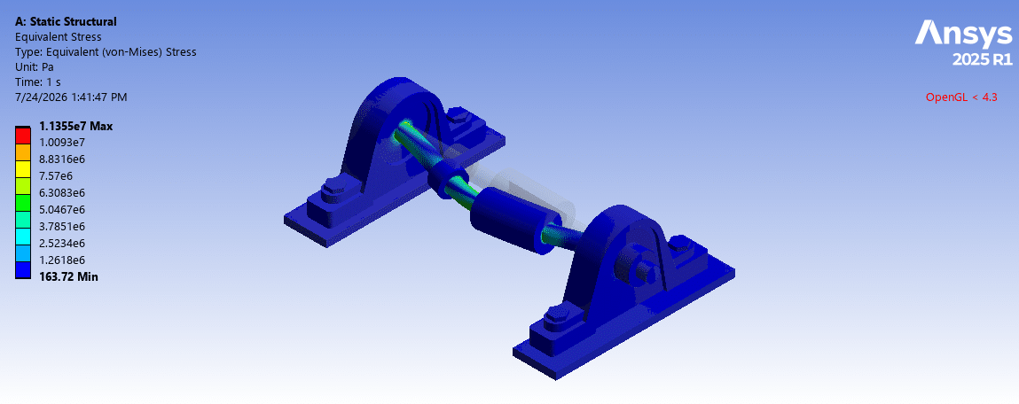
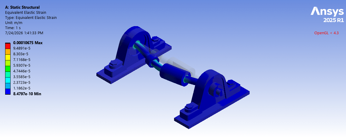
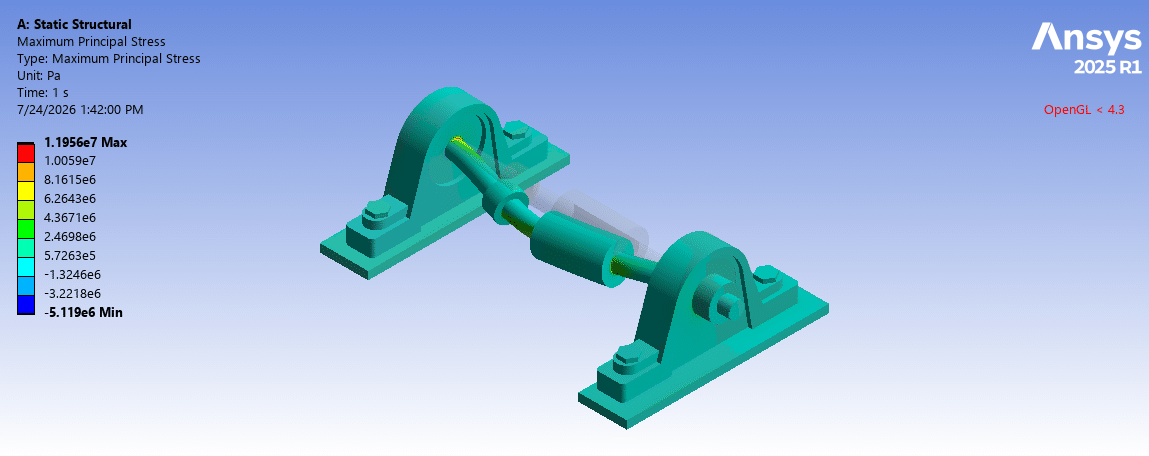
After the calculations, we obtained the contours of total deformation, equivalent strain, and equivalent (von Mises) stress over the shaft and bearing assembly.
The total deformation distribution shows that the maximum deflection occurs in the middle region of the shaft, where the pulleys are mounted. This is a result of the gravity load and belt loads acting farthest from the two end supports, while the bearing supports remain stationary. So, the shaft bending and the deflected shape are because of the resultant of the gravity and belt forces.
The stress distribution shows that the higher stress appears on the shaft inboard of the bearing supports and under the pulley seats. This is because the bending moment generated by the transverse loads is highest there.
You must be logged in to post a review.


 Talk On WhatsApp
Reviews
There are no reviews yet.