
ANSYS STRUCTURAL: Truss Bridge Static Simulation
$180.00 Internship
- This product simulates a Bridge using ANSYS Static Structural software.
- We model the 3D geometry with the Design Modeler software and mesh it as a Structured grid.
- We use Fixed Support and Pressure Load as the boundary load conditions.
To Order Your Project or benefit from a CFD consultation, contact our experts via email (info@mr-cfd.com), online support tab, or WhatsApp at +44 7443 197273.
There are some Free Products to check our service quality.
If you want the training video in another language instead of English, ask it via info@mr-cfd.com after you buy the product.
Description
ANSYS Static Structural: Bridge Analysis under Pressure Load and Fixed Support
Description
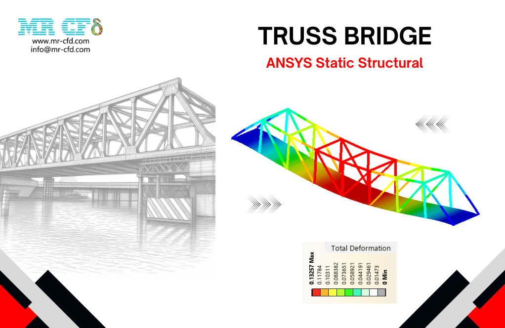
In this project, we present a structural simulation of a Truss Bridge in ANSYS Static Structural.
A bridge is a structure built to cross over ths obstacles, such as roads, rivers, valleys, or railways. In other words, a bridge is constructed to carry traffic loads safely from one side to the other by transferring loads into its supports. Bridges are classified into various types, including beam bridges, arch bridges, truss bridges, cable-stayed bridges, suspension bridges, etc.
For the present study, a truss bridge is modeled. A truss bridge is designed with straight structural members arranged in a repeating triangular pattern (in different forms). The feature of the triangular configuration is that the members carry the load mainly through tension and axial compression rather than bending. In conclusion, the truss is considered an efficient and popular bridge construction because it achieves a very high stiffness and load capacity with a relatively low self-weight.
The goal of this study is to evaluate the structural response of the truss bridge under the loading services, in the form of deflection and stress distributions.
Methodology
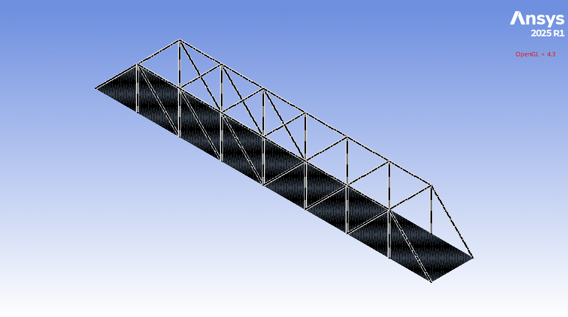
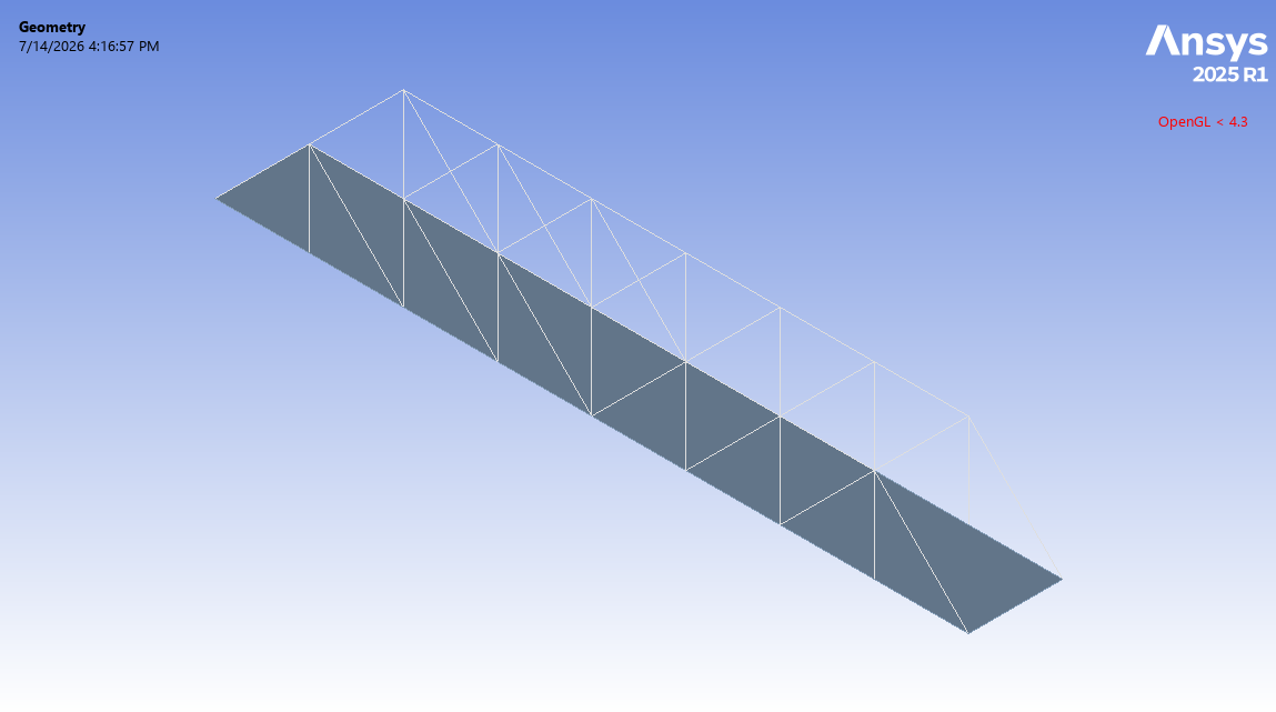
First, we modeled the geometry of the bridge with Design Modeler software. The computational domain corresponds to a truss-type bridge in which a flat rectangular plate is supported by triangular trusses. These truss members are designed with a cross-section that is extruded along the bridge lines, creating the truss frame with triangular arrangements.
Second, we meshed the domain. Because of the uniform and symmetrical construction of the bridge, a structured mesh was created, generating 22,786 elements. Finally, we completed the simulation and calculations with ANSYS Static Structural software.
It is assumed that a uniform pressure load is applied to the plate corresponding to the road, which can represent the weight of the structure and the traffic passing over it, such as vehicles. So, as the load boundary condition, we defined a continuous pressure load on the bridge structure in the downward direction.
Meanwhile, the two transverse edges at the beginning and end of the bridge structure are considered as restrained supports in the bridge design to prevent any freedom of movement or rotation of the bridge structure. Therefore, we defined the fixed support condition as the load boundary condition.
Conclusion
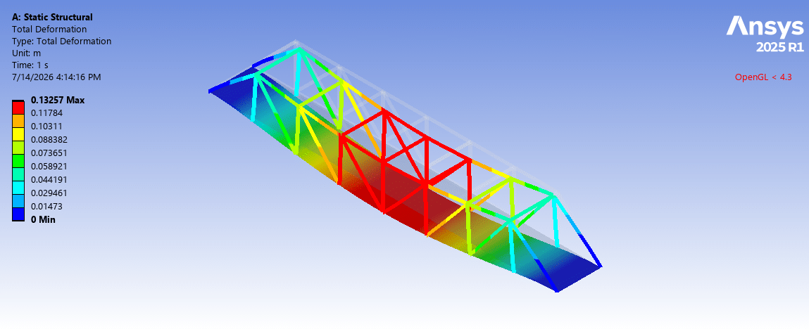
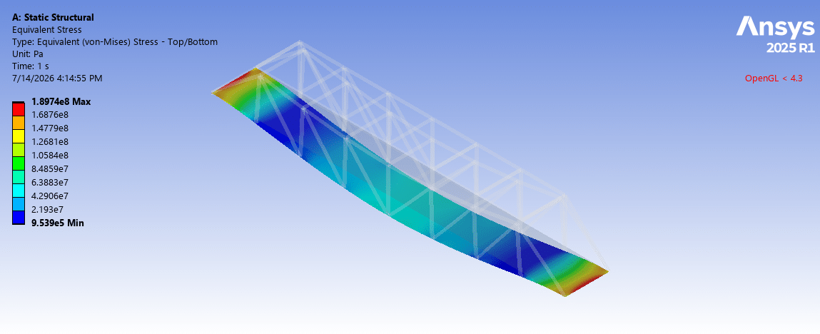
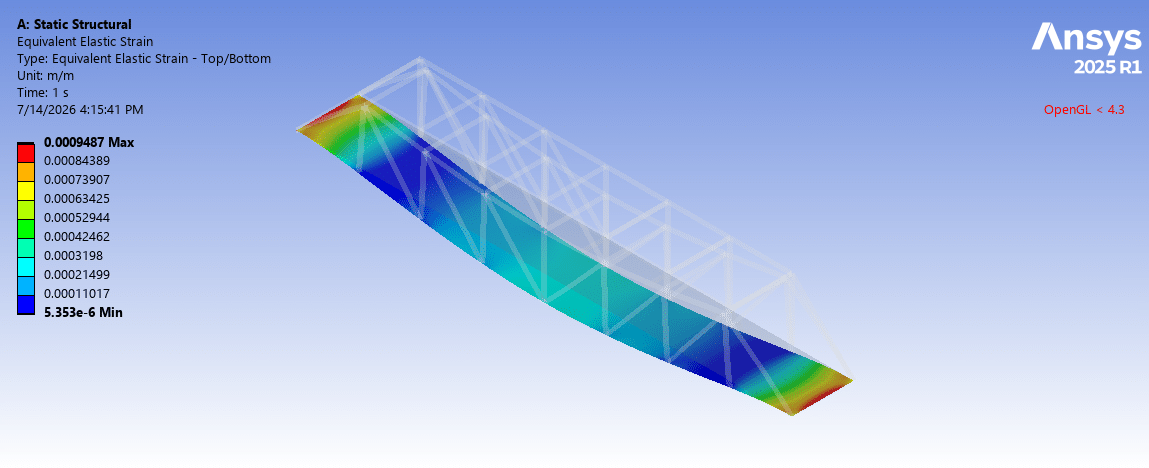
After the calculations, we obtained the contours of total deformation, equivalent strain, and equivalent (von Mises) stress over the truss bridge.
The total deformation distribution shows that maximum deflection occurs in the middle regions of the bridge, where the highest distance from the fixed supports on both sides. However, the two edges at the beginning and end of the bridge structure remain fixed, and the areas adjacent to them experience minimal deformation. This deformation analysis is fully consistent with the behavior of a bridge under a distributed load but with fixed sides.
The stress distribution indicates that the maximum value appears near the fixed support at the two transverse edges. On the one hand, transferring the entire applied load through these constrained edges, and on the other hand, due to the impossibility of deformation in these edges, causes stress to be concentrated on these supports. Meanwhile, the stress decreases toward the middle zones, where the plate is free to deflect.
You must be logged in to post a review.
 Talk On WhatsApp
Reviews
There are no reviews yet.