

Battery Module, Cooling Channels, ANSYS Fluent CFD Simulation
$630.00 Internship
- This product numerically simulates a Battery Module using ANSYS Fluent software.
- We design the 3D model with the Design Modeler software.
- We mesh the model with ANSYS Meshing software.
- We use the Circuit Network model to define the battery discharge.
- We use the NTGK sub-model to determine the electrochemical computations.
- We use a Virtual Connection to define a battery module connection.
- The run calculation is in an unsteady state (transient).
To Order Your Project or benefit from a CFD consultation, contact our experts via email (info@mr-cfd.com), online support tab, or WhatsApp at +44 7443 197273.
There are some Free Products to check our service quality.
If you want the training video in another language instead of English, ask it via info@mr-cfd.com after you buy the product.
Description
Description
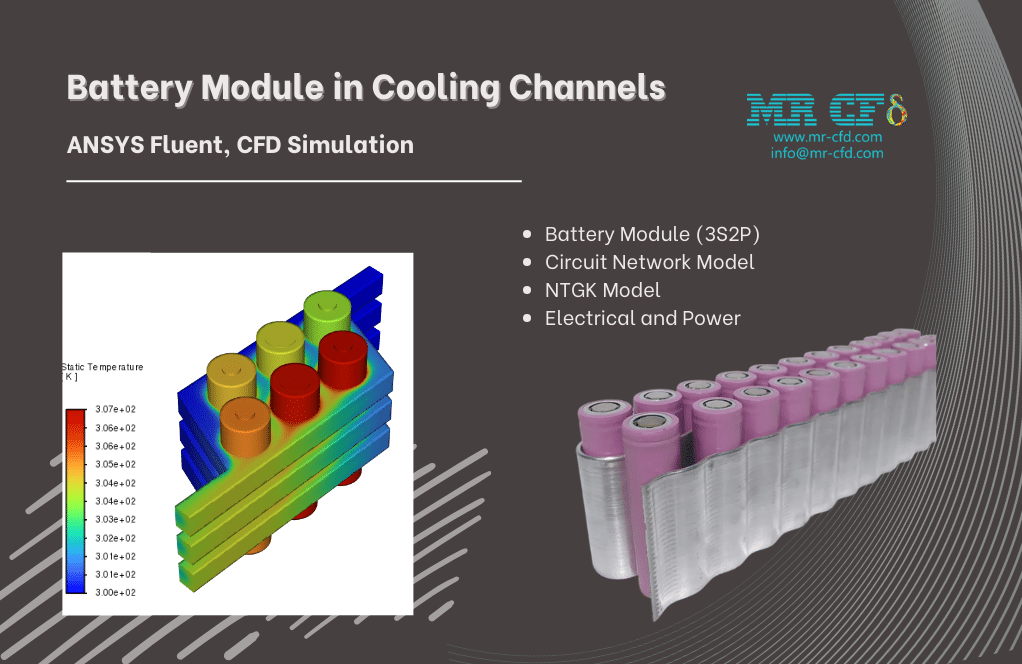
In this project, we present the CFD simulation of a battery module inside the cooling channels via ANSYS Fluent software.
A battery is a device that converts chemical energy into electric energy through chemical reactions. Several single battery cells are connected to create a battery module.
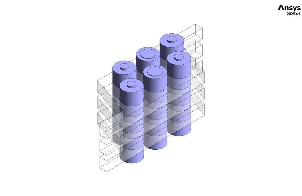
We defined 6 batteries in cylindrical-type, which have been connected in both parallel and serial configurations, to form a battery module. Our battery module consists of 3 battery series stages and 2 batteries in parallel per series stage. So, it is called the 3S2P arrangement.
In conventional, the operation of battery cells results in significant heat generation. Therefore, we designed three rows of cooling channels around the battery cells for thermal management.
Therefore, the present project focuses on electro-thermal coupled (ETC) analysis.
Methodology
We modeled the geometry of a battery module with the cooling channels around it using Design Modeler software. Next, we meshed the model using ANSYS Meshing software, and 982,917elements were generated.
Finally, we set up this battery module using the Battery model in ANSYS Fluent software.
We used the Circuit Network model for battery system modeling. Then, we used the NTGK (Newman, Tiedemann, Gu, and Kim) sub-model to specify the electrochemical computations. The NTGK model is considered a semi-empirical method for electrochemical formulation.
For present battery module modeling, we used virtual connections instead of real connections. It means that without needing to design the busbars, we loaded a text file to define the connection type.
Usually, the properties of the battery cells in the in-plane direction are different from those in the cross-plane direction. So, we defined the orthotropic thermal conductivity for the material of the cylindrical cells.
Since the discharging process in the battery system occurs over time, we run the calculation in an unsteady state (transient).
Conclusion
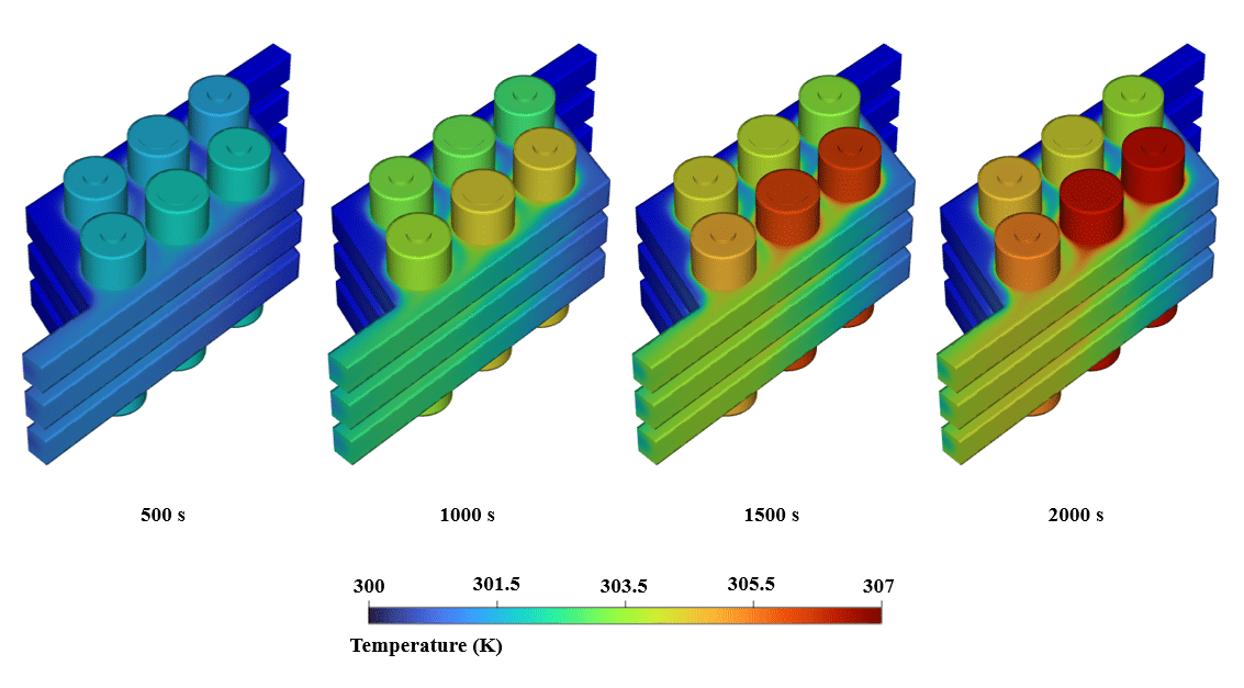
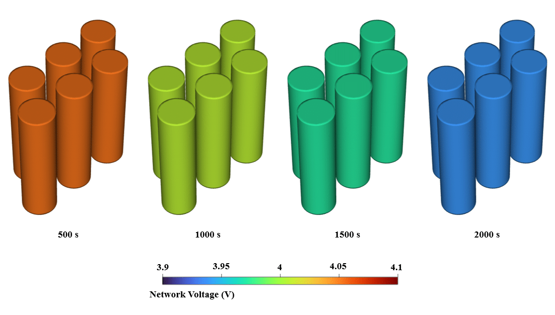
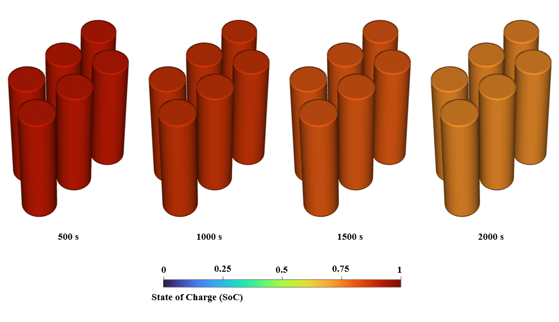
We intend to analyze the battery module’s behavior during the discharging process. Therefore, we obtained the contours of temperature, potential (network voltage), and SOC (state of charge) at different times.
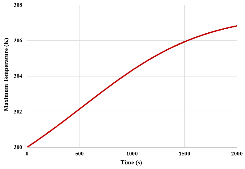
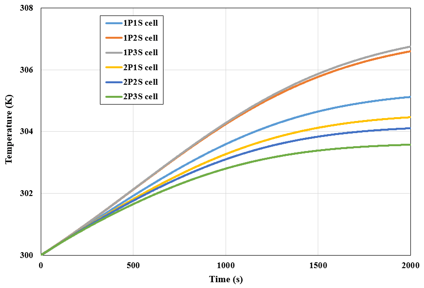
Next, we presented a plot of variations in the maximum temperature of the cells of the battery module with respect to time, and then a graph showing average temperature changes of each cell over time.
The results show that the network voltage and SOC level decrease during the discharge process, and instead, the temperature of the battery cells increases due to heat generation.
Description
In this project, we present the CFD simulation of a battery module inside the cooling channels via ANSYS Fluent software.
A battery is a device that converts chemical energy into electric energy through chemical reactions. Several single battery cells are connected to create a battery module.
We defined 6 batteries in cylindrical-type, which have been connected in both parallel and serial configurations, to form a battery module. Our battery module consists of 3 battery series stages and 2 batteries in parallel per series stage. So, it is called the 3S2P arrangement.
In conventional, the operation of battery cells results in significant heat generation. Therefore, we designed three rows of cooling channels around the battery cells for thermal management.
Therefore, the present project focuses on electro-thermal coupled (ETC) analysis.
Methodology
We modeled the geometry of a battery module with the cooling channels around it using Design Modeler software. Next, we meshed the model using ANSYS Meshing software, and 982,917elements were generated.
Finally, we set up this battery module using the Battery model in ANSYS Fluent software.
We used the Circuit Network model for battery system modeling. Then, Then, we used the NTGK (Newman, Tiedemann, Gu, and Kim) sub-model to specify the electrochemical computations. The NTGK model is considered a semi-empirical method for electrochemical formulation.
For present battery module modeling, we used virtual connections instead of real connections. It means that without needing to design the busbars, we loaded a text file to define the connection type.
Usually, the properties of the battery cells in the in-plane direction are different from those in the cross-plane direction. So, we defined the orthotropic thermal conductivity for the material of the cylindrical cells.
Since the discharging process in the battery system occurs over time, we run the calculation in an unsteady state (transient).
Conclusion
We intend to analyze the battery module’s behavior during the discharging process. Therefore, we obtained the contours of temperature, potential (network voltage), and SOC (state of charge) at different times.
Next, we presented a plot of variations in the maximum temperature of the cells of the battery module with respect to time, and then a graph showing average temperature changes of each cell over time.
The results show that the network voltage and SOC level decrease during the discharge process, and instead, the temperature of the battery cells increases due to heat generation.
You must be logged in to post a review.

 Talk On WhatsApp
Reviews
There are no reviews yet.