Francis Turbine, ANSYS Fluent CFD Simulation Training
$120.00 Student Discount
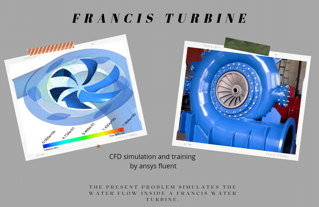
- The present problem simulates the water flow inside a Francis water turbine by ANSYS Fluent software.
- The geometry is designed using Design Modeler software.
- The meshing of the model has been done using ANSYS Meshing software and the element number is 4653160.
- Frame motion (MRF) is used to define the rotation of the blades inside the chamber.
Click on Add To Cart and obtain the Geometry file, Mesh file, and a Comprehensive ANSYS Fluent Training Video.
To Order Your Project or benefit from a CFD consultation, contact our experts via email ([email protected]), online support tab, or WhatsApp at +44 7443 197273.
There are some Free Products to check our service quality.
If you want the training video in another language instead of English, ask it via [email protected] after you buy the product.
Description
Description
The present problem simulates the water flow inside a Francis water turbine using ANSYS Fluent software. A water turbine is turbomachinery that converts kinetic energy from water flow or potential energy from water height differences into rotational motion.
Francis turbines are one of the types of water turbines that can use kinetic and potential energy for power generation at the same time due to the location of their blades.
In this type of turbine, water flows into the volute chamber because due to the blades’ circular structure, the flow of fluid colliding with the blades must be rotational to improve the system’s operational efficiency. The water flow is then transferred to the turbine runner blades with a specific flow rate, and as a result, the desired work is produced by rotating these blades by the water flow.
Finally, the outflow of water from the turbine runner blades will be axial. In the present simulation, a flow of water with a flow rate of 1.996 kg/s enters the turbine’s inner chamber with a rotational speed of 158 rpm for the blades.
Francis Methodology
Frame motion (MRF) defines the blades’ rotation inside the chamber and creates the resulting rotational flow around the blades. It is assumed that the area of water flow around the blades has a rotational motion relative to the blades, While the rotating blades have a rotational speed of zero relative to this rotating area.
The geometry is designed using Design Modeler software. In the design of the present model, two main parts have been considered, which include fixed walls that have fixed vanes with fixed angles and moving walls that have rotating vanes.
The model meshing has been done using ANSYS Meshing software, and the mesh type is unstructured. The element number is 4653160. Also, the mesh quality is considered finer in the areas close to the blades.
Francis Conclusion
At the end of the solution process, two-dimensional and three-dimensional contours related to pressure, velocity, path lines, and velocity vectors are obtained. As it is obvious, the maximum velocity occurs near the rotating blades. Also, all the possible results can be extracted, like the pressure drop equal to 2.3 e+3.


Sigmund Halvorson –
It worked for me, great. I worked on a project that I was able to use in this tutorial.
Prof. Jayden Boyer –
Has MRF been used in this case? I want to work on an academic project on this.
Myrtis Lockman Jr. –
Your job is right MR-CFD
Gaston Wyman –
What kind of boundary conditions are used in this simulation?
MR CFD Support –
The simulation uses velocity inlet and pressure outlet boundary conditions to model the flow of gas and amine solution in the sweetening process.
Mr. Myron Harris IV –
How are the results of the simulation visualized?
MR CFD Support –
The results are visualized using contour plots of pressure and velocity, as well as pathlines of the flow.
Eliezer Fay –
I am fascinated by how the Francis Turbine design improves efficiency. Could you please describe how water flows over the blades and how this enhances turbine performance?
MR CFD Support –
In the Francis Turbine, the water flows through a spiral-shaped casing known as the volute and passes over the blades which are arranged in a circular pattern. As the water collides with these blades, this design allows the water to flow smoothly and rotate the blades without much turbulence, reducing energy loss. The shape of the blades is designed to capture both kinetic and potential energy of the water, which facilitates an efficient energy transfer from water to the rotating blades, thus increasing the performance of the turbine.
Prof. Estell Ferry DDS –
Does the CFD simulation of the Francis turbine account for cavitation effects, which are common in turbines with high velocity flows?
MR CFD Support –
In this specific training course, cavitation is not explicitly mentioned. However, it is possible to include cavitation effects in a CFD simulation of a Francis turbine using ANSYS Fluent by activating the relevant models for phase change when the local pressure drops below the vapor pressure. It would depend on the defined goals and scope of the simulation whether cavitation is included or not.
Prof. Chyna Gusikowski –
I found this training material extremely thorough, and the Francis turbine CFD simulation was detailed and informative, which really helped deepen my understanding of turbomachinery flow processes.
MR CFD Support –
Thank you for your positive feedback! It’s great to hear that the training material on the Francis turbine CFD simulation was helpful to you. Should you have any further questions or need more information, please don’t hesitate to reach out!
Paula Rutherford –
I’m absolutely thrilled with the detail and clarity of the CFD simulation for the Francis Turbine. The structured approach to handle fluids with combined kinetic and potential energy was portrayed realistically. Fantastic work on representing the flow’s interaction with the turbine blades!
MR CFD Support –
Thank you for the kind words! We’re really glad to hear that you appreciated the performance and accuracy of the Francis Turbine CFD simulation. Our team works hard to ensure the simulations are as realistic and detailed as possible. If you have any further feedback or questions, please feel free to share!
Lue Koelpin –
The meticulous details in the Francis Turbine simulation are fantastic! The clarity on how water flow engages with the turbine blades for energy transformation is very helpful.
MR CFD Support –
Thank you for taking the time to leave such a positive review. We are thrilled to hear that you found the Francis Turbine simulation clear and informative. It’s our goal to provide detailed insights into complex systems like these to aid learning and application. If you have any further feedback or need more information on our other simulation topics, feel free to reach out.
Marcelo Luettgen –
I’m impressed with the accuracy of your Francis Turbine simulation—especially how the interaction between the blades and the rotating flow is modeled. Can you detail how it reflects real-world turbine efficiency rates?
MR CFD Support –
Thank you for your kind words! The simulation is designed to accurately model the flow through a Francis turbine using advanced computational fluid dynamics (CFD) techniques. By using precise boundary conditions and employing the framework of moving reference frames (MRF), the simulation replicates the turbine blades’ response to the water flow. Real-world efficiency is reflected through the careful setup of flow rates, rotational speeds, and the dynamic interaction between water and the blade surfaces. All these aspects help in predicting the turbine’s performance and efficiency under the simulated conditions, closely matching what might be expected in the real world.
Mrs. Loraine Jenkins –
Can this simulation be used to optimize the design of a Francis turbine?
MR CFD Support –
Absolutely! The results from this simulation can be used to analyze the performance of the turbine and make necessary design modifications for optimization.
Kira Murphy –
This CFD course seems really practical! Does it include any tutorials on how to interpret the simulation results?
MR CFD Support –
Yes, our Francis Turbine simulation training includes comprehensive tutorials not only on setting up and running the simulation but also on interpreting the results such as pressure and velocity distributions, path lines, and other flow characteristics important for evaluating turbine performance.
Lavonne Schmeler II –
This simulation seems impressive! Just curious, how accurate is this simulation in predicting the efficiency of the actual turbine performance?
MR CFD Support –
The simulation is designed to mimic actual turbine performance closely using sophisticated physical mathematical models. Nevertheless, the precision of predictions would depend on the specifics of the setup like boundary conditions, materials properties, and the mesh quality. CFD simulations like this can often provide valuable insight but a careful validation against experimental or operational data is crucial for accuracy.
Prof. Destiney Schiller IV –
This course was really useful for understanding the Francis turbine simulation. Can you explain what role the MRF method plays in ensuring realistic simulation results?
MR CFD Support –
The Multiple Reference Frame (MRF) method is crucial as it allows us to simulate rotating blades in steady-state conditions without requiring time-consuming transient simulations. By setting the rotating zone where the turbine blades are located, we can establish a relative motion between the liquid flow and the blades. This accurately captures the effects of blade rotation on the water flow dynamics, resulting in realistic prediction of pressures, velocities, and forces within the turbine, without directly simulating the physical motion of the blades. The stationary and rotating regions interact through interface boundaries, enabling a comprehensive simulation of the coupled dynamics within the Francis turbine.
Jan Okuneva –
I’m so impressed with the detail presented in this CFD simulation of a Francis turbine. The way the rotation of the water flow interplays with the turbine blades to accurately mimic real-world behavior and generate power is modeled exceptionally well.
MR CFD Support –
Thank you for your kind words about our Francis turbine CFD simulation training product. We’re delighted to hear that you appreciated the level of detail and accuracy in modeling the turbine’s operation. Your positive feedback encourages us to continue delivering high-quality educational content.
Jared Little –
I found the training on Francis Turbine with ANSYS Fluent very educational. The step by step methodology really enhanced my comprehension of complex fluid dynamics within turbines. The simulation results helped solidify theoretical concepts with practical observations.
MR CFD Support –
Thank you for your positive feedback! We are thrilled to hear that our training has bolstered your understanding of fluid dynamics in Francis Turbines. We strive to provide comprehensive and practical insights through our simulations, and your success with the material is extremely rewarding for our team. If you have any further questions or require additional support in your learning endeavors, please don’t hesitate to reach out.
Kallie Runolfsson –
The training was excellent and detailed. The explanation of the fluid dynamics around the blades really illuminated how Francis turbines operate. Out of curiosity, what pressure drop would we expect in a real-world scenario, approximately?
MR CFD Support –
The pressure drop observed in the simulation, equivalent to 2.3 e+3, serves as a model and can be similar to what you would expect in a real-world scenario. It’s influenced by factors like flow rate, blade design, and rotational speed.
Mr. Amparo Lemke DVM –
I was particularly impressed by the detailed analysis of the Francis Turbine simulation! One aspect I’d love to understand better is how the power output of this turbine model can be calculated or estimated from the simulation results presented here.
MR CFD Support –
Admin: Thank you for your interest and for complimenting the detailed analysis. To estimate the power output of the Francis Turbine model from the simulation results, the torque generated by the water flow on the turbine blades can be calculated. The product of this torque and the angular velocity (rotational speed) of the turbine provides the mechanical power output. In ANSYS Fluent, this is often calculated using the ‘Reports’ function, where you can select the turbine blades’ surfaces to compute the forces and moments they experience. The moment calculated about the axis of rotation, multiplied by the angular speed, yields the power output. Keep in mind, this estimated power output would be the mechanical power, and for electrical power output, you would need to account for the efficiency of the generator coupled with the turbine.
Colby Schaefer –
I was very impressed by the detailed explanation of the Francis Turbine simulation, which enhances our comprehension of hydrodynamic engineering. Can MR CFD include training on assessing the mechanical impact of the forces on the turbine structure during operation?
MR CFD Support –
We are thrilled to hear you are satisfied with the Francis Turbine CFD simulation training. Regarding your query, our courses focus on the fluid dynamics aspect of simulations using ANSYS Fluent. However, we can certainly consider creating advanced materials that delve into the structural analysis aspects using ANSYS Mechanical or incorporating fluid-structure interaction (FSI) studies in future training content. Thank you for your valuable suggestion!
Eileen Rice –
I was impressed by how the clear visualizations and path lines from the CFD results made it easy to understand the flow within the Francis turbine. Well done!
MR CFD Support –
Thank you for your kind words! We’re glad the visualizations and path lines provided a clear understanding of the complex flow within the Francis turbine. Our goal is to deliver comprehensive and insightful CFD training that helps our customers grasp the essential concepts effectively.
Hilbert Gusikowski –
The training for the Francis Turbine simulation was perfectly detailed. It gave me a solid understanding of setting up and solving turbine flow problems in ANSYS Fluent. Thanks for an amazing learning experience!
MR CFD Support –
We’re thrilled to hear that you found our Francis Turbine simulation training helpful and that it enhanced your understanding of CFD in turbomachinery. Thank you for your positive feedback!
Reva Lehner –
I am thoroughly impressed with the fluid mechanics concepts explained in your Francis Turbine Training here. The use of the MRF method to simulate the rotating blades was particularly insightful. Do you also provide information on how to post-process the results to get insights specific to efficiency or power output of the turbine?
MR CFD Support –
We appreciate your positive feedback! Yes, our training includes guidance on post-processing the results, where we demonstrate how to calculate key performance indicators such as efficiency, power output, and pressure drop across the turbine. By examining the velocity and pressure distribution results, we further instruct how to interpret these insights in the context of the turbine’s performance.
Meta Grant –
I found the training for the Francis Turbine simulation very enlightening. The detailed steps and clear methodology made the entire learning process much easier. It’s impressive seeing the simulation results and understanding the turbine dynamics!
MR CFD Support –
Thank you for your kind words! We are thrilled to hear that you found the Francis Turbine simulation training beneficial and easy to follow. Understanding the dynamics of turbines is crucial, and we’re glad our simulation helped in providing valuable insights. If you have any questions or need further assistance, don’t hesitate to reach out.
Ashleigh Pacocha –
I found the training on Francis Turbine CFD Simulation very clear and easy to follow. The setup details and the methodology were well-explained. The incorporation of Frame motion (MRF) for simulating the rotation of the blades was particularly insightful.
MR CFD Support –
Thank you so much for your positive feedback. We’re delighted to know that the training content on Francis Turbine using ANSYS Fluent was helpful and that the Frame motion (MRF) methodology was insightful for your learning. If you have any more questions or need further assistance with your simulations, don’t hesitate to reach out to us.
Mr. Pablo Beier Jr. –
This training seems really insightful! The detailed animations of the flow path lines must really help in understanding the turbine dynamics.
MR CFD Support –
Thank you for your positive feedback! We’re thrilled to hear you found the training insightful with helpful visual animations to aid in understanding the dynamics of the Francis turbine. Your appreciation means a lot to us, and we look forward to providing you with more valuable learning experiences.
Mandy Berge –
The tutorial appears very engaging, and the visualized flow results seem excellent! However, I am somewhat new to CFD and would like to understand a bit more—how does the MRF method allow us for simulating rotating parts without actually rotating the mesh?
MR CFD Support –
The Multiple Reference Frame (MRF) is a technique organic to Fluent that simulates rotation by setting one or more reference frames in the computational domain that are rotating with respect to the stationary (or inertial) frame. It doesn’t physically rotate the mesh but instead applies rotational effects to the stationary mesh via modifying fluid flow equations for frames set as rotating. This achieves the effect of the rotation while avoiding the need and complexity of deforming or re-meshing. In the case of the Francis turbine simulation, this method allows Fluent to calculate the behavior of the water as it interacts with the spinning blades without having to rotate the mesh around the blades.
Prof. Nasir Rau –
I found the simulation training very comprehensive. Learned a lot on setting up water turbines in ANSYS Fluent!
MR CFD Support –
Thank you for your positive feedback! We’re delighted to hear that the Francis Turbine CFD simulation training was comprehensive and informative for you. If there’s anything else you’d like to learn about ANSYS Fluent or turbomachinery simulations, do let us know. We aim to provide high-quality learning experiences for our customers.
Dr. Kay Stracke DVM –
I’ve been very impressed with the level of detail in the simulation outcomes, particularly the clarity in which areas experience the highest velocities. The results make it easier for me to understand the performance of a Francis turbine. Great job!
MR CFD Support –
Thank you for your positive feedback! We’re glad to hear that our simulation of the Francis turbine has provided you with a clear understanding of its operational performance and dynamics. We always strive for detail and accuracy in our training products. If there’s anything else we can assist you with, feel free to reach out!
Carolyne Friesen –
I was amazed at how detailed the simulation results were. The Francis Turbine training appeared to cover everything needed to understand water-flow dynamics within a complex system.
MR CFD Support –
Thank you for your kind words! We’re thrilled to hear that our Francis Turbine simulation training met your expectations and provided you with a comprehensive understanding of fluid dynamics in turbomachinery. Your satisfaction is our top priority, and we appreciate your feedback.
Cecil Feil V –
The simulation captures impressive details! How does varying the blade rotation rate affect output such as pressure drop and flow velocity?
MR CFD Support –
Thank you for your kind words! Changing the blade rotation rate in a Francis Turbine simulation significantly impacts the output metrics. With a higher rotation rate, you typically observe an increase in pressure drop and flow velocity due to greater energy extraction from the water flow. This also influences the overall efficiency of the turbine.
Dr. Santina Parisian –
I’m completely blown away by the results of the simulation! The level of detail in the Francis Turbine’s operation as captured in the CFD simulation is top-notch. Fantastic work on showing the velocity contours and path lines which clearly demonstrated how effectively the turbine converts energy.
MR CFD Support –
Thank you so much for your kind words! We’re thrilled to hear that you’re pleased with the accuracy and detail of the Francis Turbine CFD simulation results. It’s always our goal to provide clear and comprehensive simulations that effectively demonstrate the operational efficiencies of such complex machinery. Your positive feedback is greatly appreciated, and it motivates us to continue delivering high-quality simulations. If you have any further questions or need more information, please don’t hesitate to reach out!
Ms. Mercedes West IV –
The training for the Francis Turbine ANSYS Fluent CFD simulation was fantastic! The step-by-step process and results achieved, especially the efficiency of the rotational flow formulation were impressive. Are additional resources like videos or webinars available for learning the intricacies of Francis turbine simulations in ANSYS Fluent?
MR CFD Support –
Thank you for your wonderful feedback! We’re glad to hear that you found the Francis Turbine CFD simulation training helpful. Yes, we do offer additional resources to enhance your learning experience. Videos, webinars, and even more extensive tutorials are often available to cover the complexities of simulations like the Francis turbine in ANSYS Fluent. Please check our website or contact customer support for further information on these materials.
Eileen Stracke –
Are mesh quality and refinement handled properly near the turbine blades to capture the intricacies of the flow there?
MR CFD Support –
Indeed, in the simulation, special attention has been paid to mesh quality and refinement near the rotating turbine blades. This practice ensures that the turbulent flow and intricate pressure differences are accurately captained within these critical areas.
Jessyca Krajcik II –
The training provided clear explanations and valuable insights into setting up a Francis turbine simulation. Thank you for the thorough and engaging content!
MR CFD Support –
We’re thrilled to hear that you found the training clear and beneficial! Your feedback is much appreciated, and we’re glad it engaged you effectively. Thank you for choosing our product!
Zelda Ratke IV –
I was impressed by the described flow characteristics around the turbine blades—this really delivered the insights I needed for understanding turbine flows. Thank you!
MR CFD Support –
We greatly appreciate your kind words and are thrilled to hear that our simulation provided the insights you needed. Understanding the flow characteristics around turbine blades is essential for optimizing their performance, and we’re glad we could assist with this. Thanks for choosing our training service!