
Combustion Chamber CFD Simulation, ANSYS CFX Training
$160.00 Internship
- The problem numerically simulates the Chamber Combustion using ANSYS CFX software.
- The geometry is designed in a 3D model with the SpaceClaim software.
- We performed the mesh of the model with ANSYS Meshing software, and the element number equals 1,147,748.
- The combustion model is Eddy Dissipation.
To Order Your Project or benefit from a CFD consultation, contact our experts via email (info@mr-cfd.com), online support tab, or WhatsApp at +44 7443 197273.
There are some Free Products to check our service quality.
If you want the training video in another language instead of English, ask it via info@mr-cfd.com after you buy the product.
Description
Description
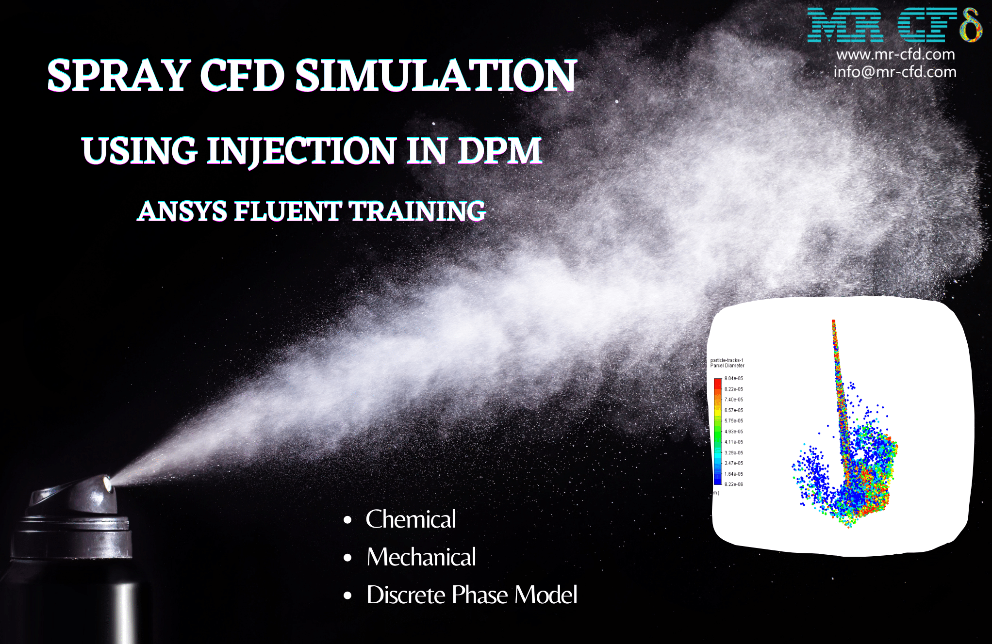
In this project, a combustion chamber is simulated using ANSYS CFX software. We perform this CFD project and investigate it by CFD analysis. The model is a cylindrical combustion chamber.
The fuel which is selected ethane in this simulation, enters the domain from a small circular boundary from the inlet boundary with the velocity value of 60 m/s. Also, the air is inserted inside with a velocity value of 2 m/s and a temperature of 300K.
Eventually, the air and ethane mix inside the chamber and the reaction occurs. Due to the reaction, the new materials are produced as products of the reaction.
The geometry of the simulation is generated inside the SpaceClaim software. Also, the meshing of this project has been done with ANSYS Meshing software. The whole element number is 1,147,748.
Combustion Chamber CFD Simulation Methodology
The reaction of Ethane Air WD1 is defined as solution reactants and the combustion model is Eddy Dissipation.
The Thermal Energy model is selected for heat transfer and the turbulence model is Scalable K-Epsilon.
The Advection Scheme and Turbulence Numerics are set to Upwind and First Order respectively.
Conclusion
At the end of the solution process, two-dimensional contours, vectors, streamlines, and volume rendering related to velocity, pressure, Temperature, and the Mass Fraction of all the components available in the simulation are obtained.
As shown in the figures, the pressure amount inside the chamber is visible, which decreases slowly and uniformly until it reaches a negative value.
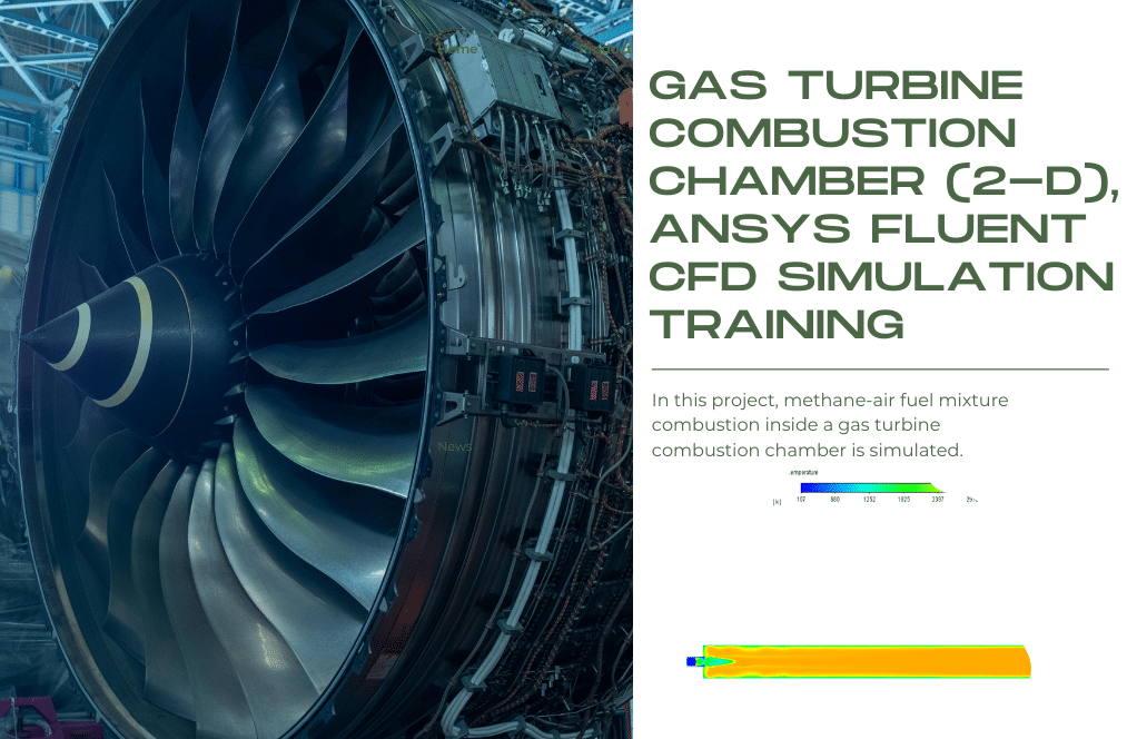
The air and ethane enter the domain from the inlet boundary conditions, mix and the reaction occurs so that the temperature of the chamber increases to more than two thousand kelvins.
Additionally, from the velocity contours, vector, and streamlines you can get how the flow exits from outlet boundary conditions in a uniform manner.
Finally, the mass fraction of all components (reactants and products) is shown in different contours.
Reviews
You must be logged in to post a review.
Travis Hills –
The combustion chamber simulation looks highly realistic. Based on the description, it’s clear that the reaction of ethane and air is captured with great attention to detail, especially with regard to temperature and pressures at various points in the chamber. The use of the Eddy Dissipation combustion model and Scalable K-Epsilon turbulence model should provide a rich and accurate representation of the chemical kinetics and fluid flow. The flow exit from the outlet would also reflect highly developed fully turbulent flow, which is excellent in conveying the physics of such a complex environment.
MR CFD Support –
Thank you for your positive feedback! We work hard to ensure the accuracy and realism of our simulations to provide valuable insights into combustion dynamics. We’re glad to hear that the details such as temperature and pressure distributions, as well as the flow behavior, meet your expectations. Your comments motivate us to continue delivering top-quality CFD learning products. If you have any further questions or need more detailed information regarding this simulation or any other aspect, feel free to reach out!
Miss Luisa Kohler –
I’m extremely impressed with how well the ethane and air mix inside the chamber leading to efficient combustion. The output of the simulation shows how the combustion process impacts temperature and flow exit. It’s fascinating!
MR CFD Support –
Thank you for your fantastic feedback! We’re thrilled to hear that our CFD simulation has provided you with valuable insights into the combustion process within the combustion chamber. Understanding the intricate details of how fuel and air mix and react under such conditions is essential, and we’re glad our software could visualize this effectively for you.
Jo Walter –
I am impressed by the level of detail in the CFD study of this combustion chamber simulation and how it uses different models for combustion and turbulence. The results that show how pressure decreases and temperature rises significantly are particularly fascinating. It’s great to see the data representations like contours and streamlines that help understand the combustion process better. Keep up the good work in providing comprehensive CFD learning materials.
MR CFD Support –
Thank you for your positive feedback! We’re delighted to hear that the detailed approach in our Combustion Chamber CFD Simulation and the use of various models provided you with clear insights into the combustion process. We strive to offer valuable learning experiences through our CFD projects, and your complement is much appreciated. Our team is continually working on more engaging content and advanced simulations for our users. Thanks for choosing our learning products.
Salvatore Stehr –
I appreciated the clarity of the explanations in the methodology section for the Combustion Chamber CFD Simulation. Seeing how various factors like velocity, temperature, and mass fraction interact within a simulation makes the learning process more practical and intuitive. It’s enlightening to witness the depth of detail one can retrieve from such simulations, especially the depiction of pressure changes and temperature increments post combustion reactions.
MR CFD Support –
Thank you for your positive feedback! We’re thrilled to hear that the methodology section of the Combustion Chamber CFD Simulation was clear and informative for you. Understanding the interaction between variables is key to mastering CFD, and we’re glad our training could convey this effectively. Your insight and enthusiasm for the detailed results and their practical implications are exactly what we strive for in our trainings. If you have any further questions or need assistance with other simulations, feel free to reach out!
Eliane Bartell DDS –
I truly appreciated the way the combustion reaction was detailed out in this simulation, including how the interaction between the air and ethane leads to the creation of new materials. The careful control of boundary conditions that enabled this complex reaction to be accurately represented in ANSYS CFX is exceptional. The results showing detailed contours of temperature and pressure truly demonstrate the capabilities of the software and the expertise of the team handling the simulation. The visualization of such a high-temperature reaction leading to a temperature increase to more than two thousand kelvins offers deep insights into the combustion process within the chamber.
MR CFD Support –
Thank you for your thoughtful review! We are pleased to hear that the detailed visualization and accurate simulation results met your expectations. Our intention is always to provide a comprehensive understanding through our CFD simulations, capturing the nuances of the combustion process. Your appreciation for the careful set-up and resultant detailed contours makes our efforts feel valued. We look forward to continuing to provide products that help with understanding complex reactions like these.
Ed Gusikowski –
I was impressed with the clarity of the combustion process in this simulation. The temperature changes and reaction dynamics were demonstrated impressively.
MR CFD Support –
Thank you for your positive feedback! We’re thrilled to hear that the combustion process and temperature dynamics were clearly illustrated in the simulation. At MR CFD Company, we strive to provide comprehensive and easy-to-understand CFD analyses, and it’s rewarding to know that our efforts are appreciated. If you have further interest in our products or need assistance with your simulations, feel free to reach out. Thank you for choosing our ANSYS CFX training for your educational needs!