
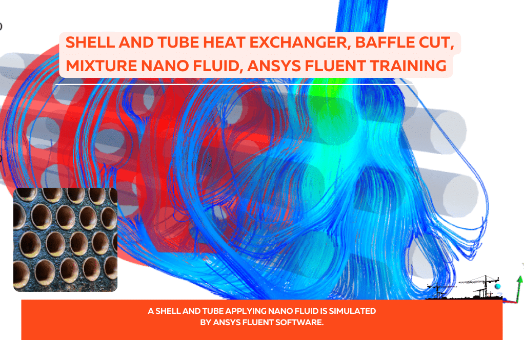
Shell and Tube Heat Exchanger with a spiral Baffle
$80.00 Internship
The problem simulates heat transfer inside a shell and tube heat exchanger with a spiral buffer.
Click on Add To Cart and obtain the Geometry file, Mesh file, and a Comprehensive ANSYS Fluent Training Video.To Order Your Project or benefit from a CFD consultation, contact our experts via email (info@mr-cfd.com), online support tab, or WhatsApp at +44 7443 197273.
There are some Free Products to check our service quality.
If you want the training video in another language instead of English, ask it via info@mr-cfd.com after you buy the product.
Description
Shell and Tube Heat Exchanger with a spiral Baffle, ANSYS Fluent CFD Simulation Training
The problem simulates heat transfer inside a shell and tube heat exchanger with a spiral buffer by ANSYS Fluent software. The heat exchanger is a device for transferring heat between two hot and cold fluids. The industry’s two most common heat exchangers are plate heat exchangers and shell and tube heat exchangers. The shell and tube heat exchangers consist of a cylindrical outer shell and inner tubes inside.
One of the cold or hot fluids passes through the space between the tubes and the outer shell, and the other fluid passes through the inner space of the inner tubes in the same direction or vice versa. One way to enhance the heat transfer process between two fluids is to use buffers inside the shell’s fluid flow path.
The use of buffers in the flow of fluid causes turbulence in the fluid flow through the shell and further contact of the fluid with the tubes, and as a result, heat transfer is enhanced; But on the other hand, it causes a pressure drop in the fluid as well as the deposition of fluid in the shell. Therefore, the use of helical baffle reduces the pressure drop and sedimentation inside the heat exchanger in addition to strengthening the heat transfer between the two fluids.
In the current model, the heat exchanger consists of seven internal tubes and a spiral buffer inside the shell. The flow of water with a flow rate of 0.5 kg.s-1 and a temperature of 300 K enters the shell from the shell inlet and is exchanged with tubes with a constant temperature of 450 K.
In fact, it is assumed that the cold flow passes through the shell and the hot flow through the inner tubes; But for simplicity, the model assumes that the temperature of the hot fluid flowing through the tubes during the process has a constant temperature value, which is assumed to be 450 K.
Shell and Tube HEX Geometry & Mesh
The present 3-D model is designed using Design Modeler software. The model is a shell and tube heat exchanger that includes an external shell and seven internal tubes inside. The diameter of the shell is 3 cm and its length is 60 cm. Inside the interior and between the shell and the tube, a spiral buffer is used. The following figure shows a view of the geometry.

The meshing of the model has been done using ANSYS Meshing software and the mesh type is unstructured. The element number is 1629340 and the accuracy of the cells in the areas adjacent to the wall of the tubes is higher. The following figure shows a view of the mesh.

CFD Simulation
To simulate the present problem, several assumptions are considered:
- The simulation is steady-state.
- The solver is pressure-based.
- The effect of the gravity on the fluid flow is 9.81 m.s-2 along the y-axis downward.
A summary of the steps for defining the problem and its solution is given in the following table:
| Models (shell and tube) | |||
| k-epsilon | Viscous model | ||
| realizable | k-epsilon model | ||
| standard wall function | near-wall treatment | ||
| on | Energy | ||
| Boundary conditions (shell and tube) | |||
| mass flow inlet | Inlet | ||
| 0.5 kg.s-1 | mass flow rate | ||
| 300 K | temperature | ||
| Pressure outlet | Outlet | ||
| 0 Pa | gauge pressure | ||
| wall | Baffle’s wall | ||
| stationary wall | wall motion | (shell and tube) | |
| coupled | thermal condition | ||
| Outer wall for shell | |||
| stationary wall | wall motion | ||
| 0 W.m-2 | heat flux | ||
| wall | Inner walls for tubes | ||
| stationary wall | wall motion | ||
| 450 K | temperature | ||
| Solution Methods (shell and tube) | |||
| Simple | Pressure-velocity coupling | ||
| Standard | pressure | Spatial discretization | |
| first-order upwind | momentum | ||
| first-order upwind | turbulent kinetic energy | ||
| first-order upwind | turbulent dissipation rate | ||
| first-order upwind | energy | ||
| Initialization (shell and tube) | |||
| Standard | Initialization method | ||
| 0 Pa | gauge pressure | ||
| 0 m.s-1 | x-velocity, z-velocity | ||
| 0.7106586 m.s-1 | y-velocity | ||
| 300 K | temperature | ||
Shell and Tube Results
At the end of the solution process, two-dimensional and three-dimensional contours of pressure, temperature, and velocity, as well as two-dimensional and three-dimensional velocity vectors and path lines, are obtained.
2 reviews for Shell and Tube Heat Exchanger with a spiral Baffle
You must be logged in to post a review.

Ms. Alanna Grimes –
I am extremely impressed with the Shell and Tube Heat Exchanger with a spiral Baffle CFD Simulation Training. It was thorough and covered important aspects like the setup for heat exchange enhancement, the specifics of the geometry and meshing, and clear solution strategies and methods. The use of a spiral baffle as an innovative design approach to boost heat transfer while mitigating pressure drop and sedimentation really stood out in the training material! Great work!
MR CFD Support –
Thank you so much for your review and for noticing the innovation behind employing a spiral baffle in the heat exchanger simulation. We are thrilled that you found the training material to be thorough and helpful for understanding both the geometry and the solution strategies. Your feedback is valuable to us as we strive to provide comprehensive learning experiences with attention to detail and the usage of cutting-edge approaches.
Tyrel Feeney –
I’m amazed at how the spiral baffle design enhances heat transfer efficiency. Do you incorporate any specific materials for spirals to reduce pressure drops further?
MR CFD Support –
Thank you for your positive feedback! In shell and tube heat exchangers, material selection for components like baffles can indeed influence the performance, including pressure drops. Although our given data does not specify the material used for the spiral baffles, typically, engineers may choose materials with a balance of strength and a low friction coefficient to minimize pressure loss while maintaining durability. Common materials may include various metals or even advanced composites, depending on the application requirements and considerations like thermal conductivity and corrosion resistance.
Barney Russel –
How does this simulation take into account the impact of heat exchanger fouling on heat transfer?
MR CFD Support –
The simulation includes advanced models for heat exchanger fouling, which can significantly affect heat transfer performance. It can simulate the impact of factors such as fouling thickness, fouling thermal conductivity, and fouling resistance on heat transfer
Prof. Mallory Sanford DDS –
This product really helped me understand heat exchangers on a deeper level! The detailed steps for setting up the simulation in ANSYS Fluent are much appreciated. The inclusion of spiral baffles as a focus for effectively enhancing heat transfer while reducing pressure drop and sedimentation was particularly insightful. The clear explanation of boundary conditions and solver settings made setting up my own simulation so much simpler. Thank you MR CFD for such a comprehensive learning tool!
MR CFD Support –
We’re thrilled to hear that our Shell and Tube with Spiral Baffle CFD simulation training has been so beneficial to your learning process! Thank you for taking the time to acknowledge the details and the set-up guidance we provided. Your satisfaction with the educational content is our biggest reward. Remember, if you ever require any assistance as you explore more complex simulations, our team at MR CFD is just a message away. Keep enjoying the learning journey!
Jessy Fisher I –
The ANSYS Fluent heat exchanger simulation with the spiral baffle really impressed me. Great to see how innovative designs can impact performance. Do you have other examples involving heat recovery systems or alternative energy devices?
MR CFD Support –
Thank you for appreciating our simulation training course on a shell and tube heat exchanger with a spiral baffle. We’re thrilled to hear you were impressed with the creative problem-solving we demonstrated. We do have a wide range of training materials and examples, including simulations on heat recovery systems and alternative energy devices. Please visit our product gallery or course listings for more information on such simulations that focus on energy efficiency and innovative engineering solutions.
Marie Wallace –
Would you please tell me when do we use “Coupled” thermal condition in the wall boundaries?
melika maysoori –
Hi Marie. Sure 🙂 . If the wall is two-sided, i.e., a wall boundary is located between two areas of connection (fluid-fluid or fluid-solid), the problem of conjugated heat transfer is raised. In such a case, when the Mesh file is read by Fluent software, a virtual wall called Shadow is automatically assigned to each of the two-sided walls. For example, if the boundary of a Wall-1 is a double-sided wall. After calling in Fluent, the Wall-1-shadow virtual wall border is created, which corresponds precisely to the Wall-1 border, and each of these borders is connected to one of the two connection areas. In such conditions, different boundary conditions can be considered for the two walls, or by selecting the Coupled option, the heat transfer of the two walls is affected by each other and is in the form of a couple. The following describes how to define the thermal conditions for a double-sided wall in a coupled or separate manner.
If both sides of the wall are coupled, select the Coupled option (Coupled thermal condition appears only in the boundary condition of the double-walled walls). In this case, the definition of other parameters is unnecessary because Fluent software automatically calculates the heat transfer in the wall based on the values calculated in the elements adjacent to the wall. The material, thickness, and amount of heat production of the wall can be determined to calulate the thin walls. It is noteworthy that the definition of these parameters for a wall is automatically considered for its corresponding virtual wall.
Barbara –
This tutorial helped me with my project.
Many thanks for your assistance.
melika maysoori –
You’re welcome. 🙂 If you need more training, you can refer to the rest of our related products, or contact us for private online training.
Jarret Schumm –
The simulation explanation is very comprehensive, but can you tell if the spiral baffle’s specific geometry significantly impacts the heat transfer enhancement compared to traditional baffles?
MR CFD Support –
Yes, the spiral baffle’s specific geometry has an important role in enhancing heat transfer efficiency. Its design induces a helical flow path for the shell-side fluid, which increases turbulence and improves the heat exchange between fluids by enhancing the overall contact time and surface area available for heat transfer. Moreover, the spiral design minimizes the risk of dead zones that can occur in shell and tube heat exchangers with segmental baffles, and reduces the pressure drop across the heat exchanger.
Miss Aliya Rippin –
I’m truly impressed with the thoroughness of the design process for the Shell and Tube Heat Exchanger with a spiral Baffle CFD Simulation. The meticulous attention to detail shown in defining the meshing, boundary conditions, and the solution methods gives me great confidence in the accuracy of the simulation. It’s evident that the simulation strikes a good balance between enhancing heat transfer efficiency and minimizing pressure drop and sedimentation!
MR CFD Support –
Thank you for your kind words and appreciation of our CFD Simulation training on the Shell and Tube Heat Exchanger with a spiral Baffle. We continuously strive to provide concise yet detailed training materials, and we’re glad to know that our efforts are well-received. Your feedback is a great motivator for us to keep up the good work!
Ebba Jacobson –
How does this simulation take into account the impact of the spiral buffer on heat transfer?
MR CFD Support –
The simulation includes advanced models for the spiral buffer, which can significantly enhance heat transfer in the heat exchanger. It can simulate the impact of factors such as buffer size, shape, and material on heat transfer performance.
Gilbert Cartwright –
How does this simulation model the process of conduction in heat transfer?
MR CFD Support –
The simulation includes advanced models for conductive heat transfer, which is an important factor in heat exchangers. It can simulate the impact of factors such as material properties, temperature gradient, and contact area on conductive heat transfer.
Dr. Adam McGlynn DVM –
Just fantastic! The spiral baffle design in this heat exchanger simulation has really piqued my interest. I’m impressed by the increase in heat transfer efficiency with a reduction in pressure drop and sedimentation. Great work!
MR CFD Support –
We greatly appreciate your feedback! It’s fantastic to hear that our simulation of the shell and tube heat exchanger with a spiral baffle has caught your attention and you’re pleased with the added efficiency it demonstrates. Thank you for taking the time to share your positive review.
Stefanie Ryan –
Can this simulation be used to evaluate the impact of different buffer designs on heat transfer?
MR CFD Support –
Yes, the simulation can be adjusted to evaluate the impact of different buffer designs on heat transfer. This includes different buffer sizes, shapes, and materials.
Carlee Kuhn –
Absolutely fantastic course on Shell and Tube Heat Exchanger simulations! The section on how spiral baffles reduce pressure drop while enhancing heat transfer was incredibly informative. It’s clear that a great deal of thought and effort has gone into crafting this hands-on training. Truly a valuable resource for anyone looking to deepen their understanding of CFD in practical applications.
MR CFD Support –
Thank you so much for your kind words! We are thrilled to hear that our course on Shell and Tube Heat Exchanger simulations with spiral baffles has been so informative and helpful. Your feedback is greatly appreciated, and we are glad you found the course valuable. If you need any further assistance or have more inquiries about our CFD training, don’t hesitate to reach out!
Prof. Ola Hansen –
This ANSYS Fluent course on Shell and Tube Heat Exchanger with a spiral baffle was well worth the investment. The spiral baffle concept and how it minimizes pressure drop and sedimentation is fascinating. The detailed insights into heat exchanger design were particularly beneficial, and the course content went thoroughly into the practical aspects of simulation, which I truly appreciate.
MR CFD Support –
Thank you so much for your thoughtful review! We’re delighted to hear that you found the course on Shell and Tube Heat Exchanger with a spiral baffle both informative and practically valuable. It’s great to know that you could gain insights into the design and simulation processes of heat exchangers. We strive to deliver comprehensive training, and your feedback reaffirms our commitment to quality. If you have any further questions or need more assistance, we’re always here to help!
Salvatore Blick –
I’ve been using the simulation training for the Shell and Tube Heat Exchanger with a spiral baffle. The explanations and the step-wise operations really enhanced my understanding. The project complexity was made much simpler to understand. This is amazing learning material for anyone interested in CFD of heat exchangers.
MR CFD Support –
We’re thrilled to hear that our simulation training for the Shell and Tube Heat Exchanger with a spiral baffle was beneficial to you! Thank you for taking the time to share your experience. It’s our mission to provide clear and comprehensive learning materials. If you have any more questions or need further assistance, please don’t hesitate to reach out. We appreciate your feedback and look forward to assisting you in your continued learning in CFD!
Estelle Ferry –
I just completed the ‘Shell and Tube Heat Exchanger with a spiral Baffle’ CFD simulation training and found the explicit explanation of boundary conditions and solution methods to be incredibly helpful for visualizing real-world thermal processes. Thank you for such a detailed and insightful course!
MR CFD Support –
Thank you for your positive feedback! We are thrilled to hear that you found the training detailed and helpful for understanding complex thermal systems. Your success is what drives us to create comprehensive learning materials. If you have any more questions or need further clarification on any topic, please feel free to reach out!
Katelin Willms –
I’m fascinated by how the spiral baffle enhances heat transfer while decreasing pressure drop in the system. Could you explain more on its shape and how it achieves this balance effectively?
MR CFD Support –
The spiral baffle in this heat exchanger is designed to create a helical flow path for the fluid passing through the shell. This shape increases turbulence, which enhances the heat transfer by forcing more fluid to come into contact with the tube surfaces. Moreover, the geometry of the spiral is optimized to minimize obstructions to the flow, reducing the pressure drop compared to traditional segmental baffles. The strategic placement and the smooth curvature of the spiral baffle are crucial for maintaining this balance between improved heat transfer and pressure drop control.