
Cycloidal Rotor: 2D CFD Simulation of Geometrical Effects on Performance; Paper Validation
$2,160.00 $1,296.00 HPC
- This project presents a three-dimensional transient CFD simulation of a four-blade cycloidal rotor using ANSYS Fluent with a moving mesh approach.
- The rotor uses NACA 0015 blades with prescribed pitching motion, and the flow is modeled with the SST k-omega turbulence model in an unstructured mesh domain.
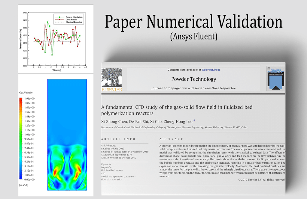
- Aerodynamic loads, disk loading, and power loading are computed from the transient solution and compared with the article “Numerical Modelling of Geometrical Effects in the Performance of a Cycloidal Rotor.”
- The close agreement between the numerical results and the published data confirms the validity of the geometry, mesh, and solver settings used in this study.
To Order Your Project or benefit from a CFD consultation, contact our experts via email (info@mr-cfd.com), online support tab, or WhatsApp at +44 7443 197273.
There are some Free Products to check our service quality.
If you want the training video in another language instead of English, ask it via info@mr-cfd.com after you buy the product.
Description
Cycloidal Rotor: 2D CFD Simulation of Geometrical Effects on Performance; Paper Validation
Project Description
A cycloidal rotor is a device that can have multiple blades that rotate both around the axis of the device and around its own axis. Approximately the blades change their pitch twice during each full turn so they can generate lift or thrust in any direction perpendicular to the rotor’s axis.. Today, cycloidal rotors are used for the propulsion of aerial vehicles, including drones and water vehicles. A unique aspect is that it can change the amount and direction of thrust without requiring any tilt of the aircraft’s structure.
In the Cycloidal Rotor projects, a three-dimensional transient CFD simulation is carried out in ANSYS Fluent to reproduce and validate the results of the article “Numerical Modelling of Geometrical Effects in the Performance of a Cycloidal Rotor”. The rotor consists of a single hub that carries four pitching blades operating in the air. The main objective is to predict the aerodynamic performance of the cycloidal rotor, especially disk loading and power loading, and to compare the numerical results with the correlations and data presented in the reference article. The complete workflow includes geometry creation in ANSYS DesignModeler, unstructured mesh generation in ANSYS Meshing, and time-accurate moving mesh simulations in ANSYS Fluent, followed by post-processing of the flow field and performance coefficients.
Geometry and Mesh
The rotor is equipped with four identical blades with a NACA 0015 airfoil section. Each blade of Cycloidal Rotor has a chord length of 1 m and rotates about a pitch axis located at 0.25 of the chord. The blades are mounted on a circular rotor placed inside a larger outer domain that represents the surrounding flow field. To provide good control over the grid resolution and allow for blade motion, the computational domain is divided into six fluid zones: four local cylindrical zones surrounding each blade, one circular rotor zone encompassing the four blade zones, and one outer stationary far-field domain. The geometry of Cycloidal Rotor created in DesignModeler and discretized in ANSYS Meshing with an unstructured tetrahedral mesh refined around the airfoils and in the near wake region. The final grid contains 169,277 cells, with a higher density near the blade surfaces and in the interface regions between zones, to accurately capture the large pressure and velocity gradients.
Solver Setup and Physical Models
The mesh of Cycloidal Rotor imported into ANSYS Fluent and solved using a pressure-based transient solver. Air is modeled as an incompressible Newtonian fluid. Turbulence is captured with the SST (k-Omega) model, which is suitable for flows with strong adverse pressure gradients and possible separation around pitching blades. Moving mesh is activated for the five rotor-related zones (the four blade zones plus the rotor zone), while the outer far field domain remains stationary. Pressure inlet and pressure outlet boundary conditions are imposed at the inlet and outlet of the external domain, respectively. The pressure-based coupled algorithm is used for pressure-velocity coupling to achieve robust convergence within each time step. The prescribed pitching motion of each blade is implemented via an “Experesion” mesh motion law. The blade pitch angle (Ɵ (t)) and its angular velocity (ω (t)) are defined as

Where (Ω) is the rotor angular velocity in rad/s, (t) is the time, (Ψ0) is the initial phase angle that specifies the blade position at (t = 0), and (α0) is the pitch angle amplitude equal to the pitch angle range of the blade. In this study, the pitch angle oscillates between (-40○) and (+40○), and the rotor rotates counterclockwise about its axis while each blade pitches about the axis located at 0.25c.
Results and Validation
The generated mesh and moving mesh strategy produce smooth deformation around the blades and maintain good element quality throughout the motion. Contours of static pressure show low-pressure regions on the suction sides of the blades and high pressure on the pressure sides, with strong gradients near the leading and trailing edges. Velocity magnitude contours highlight high-speed flow around the blades and the development of interacting wakes inside the rotor zone that gradually diffuse toward the outer domain. From the transient solution, the instantaneous forces on the blades are integrated over one or more rotor revolutions to obtain the mean thrust, torque, disk loading, and power loading at different rotor speeds. These numerical results are compared with the performance curve for disk load versus power load reported in the article. In the validation plot, the present CFD points for 400 rpm and 1000 rpm are placed on the same diagram as the article data. The CFD point at 400 rpm lies near the high power loading, low disk loading region, and the point at 1000 rpm appears close to the low power loading, high disk loading region, following the decreasing trend of the reference curve. The good agreement between the simulated points and the article correlation confirms that the current numerical model, including the geometrical representation, moving mesh law, and SST (k- Omega) turbulence model, can successfully reproduce the aerodynamic performance of the cycloidal rotor.
Ultimately, we can use this setup for other cycloidal rotor simulations, such as we use in Cycloidal Rotor: 3D CFD Simulation of Geometrical Effects on Performance
You must be logged in to post a review.

Reviews
There are no reviews yet.