PCM in Triplex Tube Internal-External Fin, Paper Validation
$280.00 Student Discount
- The problem numerically simulates the PCM Melting in Triplex Tube with Internal–External Fins using ANSYS Fluent software.
- We design the 3-D model with the Design Modeler software.
- We mesh the model with ANSYS Meshing software, and the element number equals 17856.
- We perform this simulation as unsteady (Transient).
- We define the Solidification and Melting model to define phase change material.
- This simulation is validated with a reference article.
To Order Your Project or benefit from a CFD consultation, contact our experts via email ([email protected]), online support tab, or WhatsApp at +44 7443 197273.
There are some Free Products to check our service quality.
If you want the training video in another language instead of English, ask it via [email protected] after you buy the product.
Description
PCM Melting in Triplex Tube with Internal–External Fins, Paper Numerical Validation, CFD Simulation by ANSYS Fluent
The present problem simulates the process of Melting PCM in a Triplex Tube Internal-External Fin using ANSYS Fluent software.
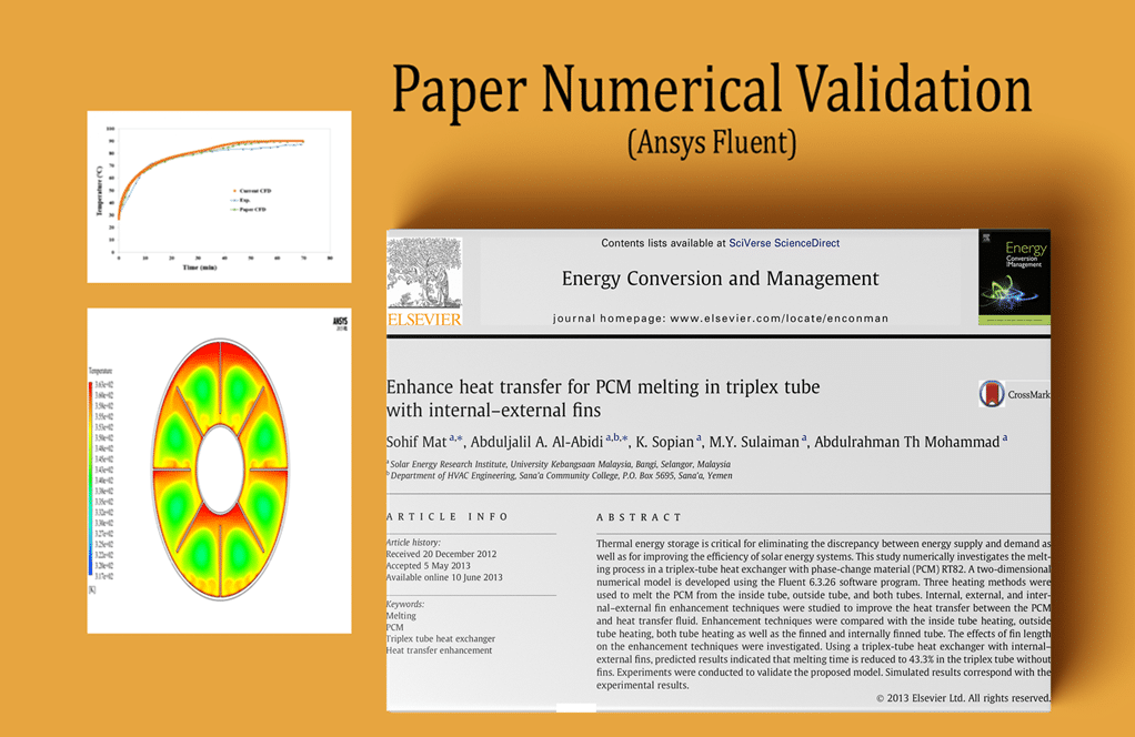
The simulation is based on the data in the reference article [Enhance heat transfer for PCM melting in a triplex tube with internal-external fins]. The results are compared and validated with the results in the paper.
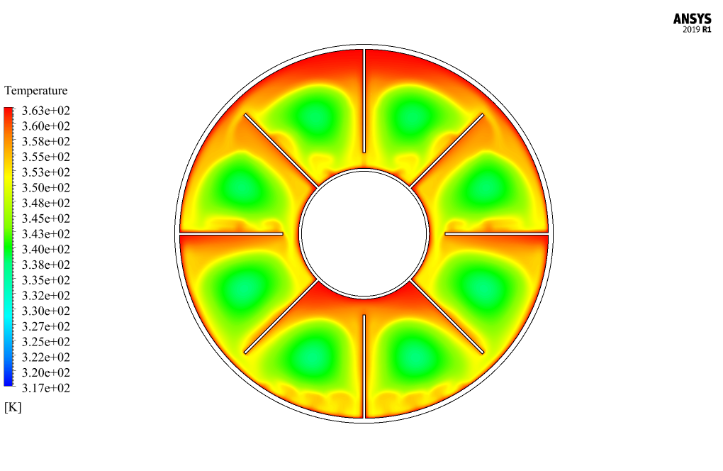
This simulation is performed in two dimensions; hence, only a hollow circular section of the pipe is modeled.
The pipe has 4 rows of outer fins connected to the inner diameter wall of the pipe and 4 rows of inner fins connected to the outer diameter wall of the pipe; So, the material of these inner and outer walls, as well as their fins, is made of copper.
Inside the tube, the phase change material is RT-82. So it has an initial density of 770 kg.m-3 in the Boussinesq model, specific heat capacity equal to 2000 j.kg-1.K-1 and thermal conductivity equal to 0.2 W/m.K and viscosity equal to 0.03499 kg/m.s.
The present model is designed in two dimensions using Design Modeler software. The model consists of a circular cross-section of a pipe with 4 rows of outer fins on the tube’s inner wall and 4 rows of inner fins on the outer wall of the tube.
The meshing has been done using ANSYS Meshing software, and the mesh type is structured. The element number is 17856.
Triplex Tube Methodology
Since the present work aims to investigate the changes in solid and liquid phases due to melting and freezing over time, the solidification and melting model has been used.
To define the solidification and melting model, the maximum temperature at which only the liquid phase prevails (T_solidus) is equal to 70 ℃.
The minimum temperature at which only the liquid phase is dominant (T_liquidus) is equal to 82 ℃, and the latent heat of solvent melting in the pure state (pure solvent melting heat) is equivalent to 176000 j/kg.
The inner wall of the tube, its outer fins, and the outer wall of the tube and its inner fins have a constant temperature equal to 90 ℃, While the phase change material inside the tube has an initial temperature of 27 ℃.
The simulation is unsteady because the present work aims to investigate the process of melting the phase change material inside the tube over time.
PCM in Triplex Tube Internal-External Fin Conclusion
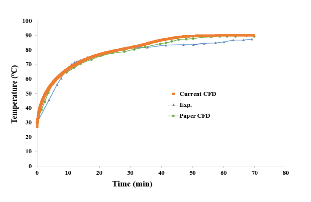
At the end of the simulation process, the results of the present work are compared and validated with the results in the paper.
For this purpose, the diagrams in Figures 7 and 13 of the paper are used, which are related to changes in the average temperature of phase change materials over time and changes in the liquid mass fraction resulting from the melting process over time, respectively.
The present work is related to the state of the paper in which the phase change materials are simultaneously affected by the inner and outer fins. The following figures show the comparison of the results of the present CFD simulation with the results of the article.
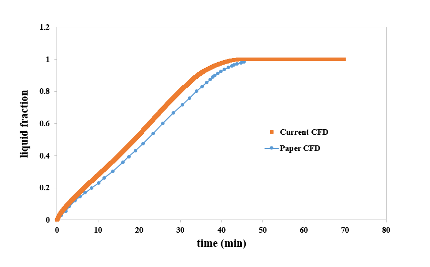
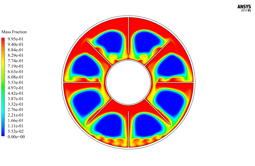
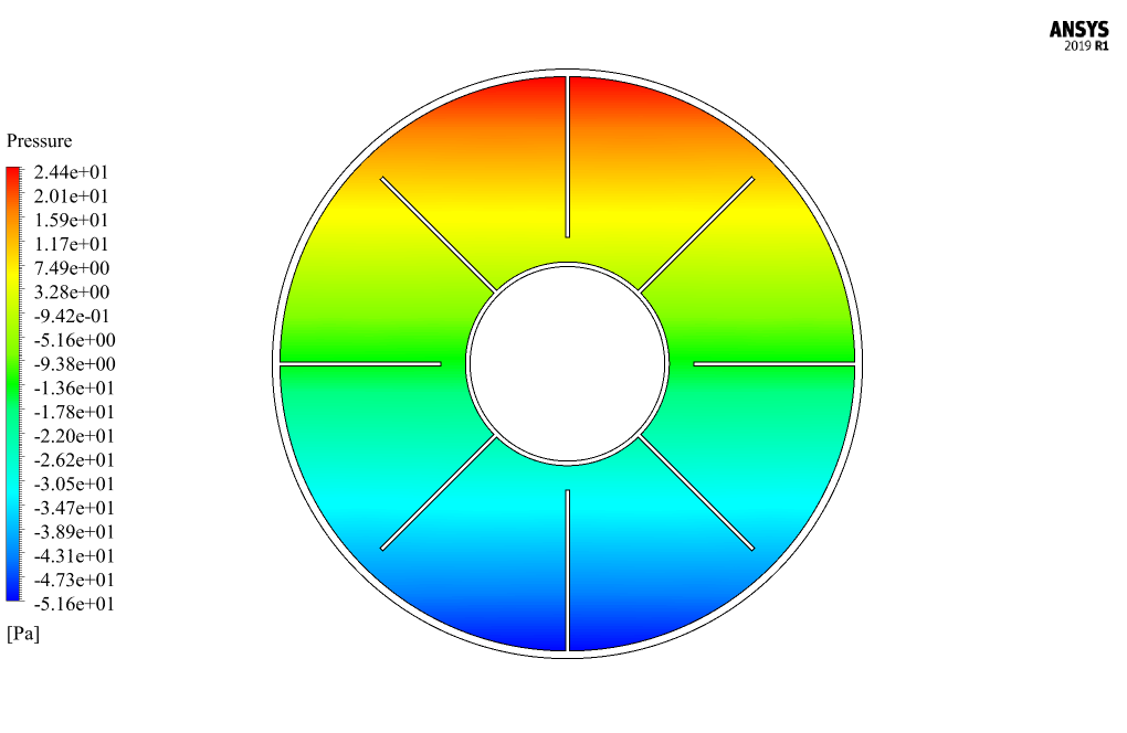
Also, after the solution process, two-dimensional contours related to pressure and temperature and the liquid mass fraction resulting from the melting process are obtained. Because the simulation process is transient, the present work results are taken at different times of the simulation output.


Robb Russel –
I’m astounded by the detailed matching of results with the reference paper’s findings! Can you elucidate on how such a precise numerical validation was achieved?
MR CFD Support –
The precision in numerical validation is achieved by meticulously setting up the simulation parameters. These include accurately inputting the properties of the PCM and the materials as per the reference, applying the correct boundary conditions, employing the solidification and melting model with detailed adjustment of parameters like the T_solidus, T_liquidus, and the latent heat of melting, and ensuring spatial and temporal resolution is high enough to capture the intricate details of the phase change process. The computational model created in ANSYS Fluent was then methodically matched to the geometries and thermal conditions given in the paper, through substantially fine meshing and unsteady-state simulation to observe the PCM transitions over time.
Zetta Block –
This Triplex Tube simulation looks extremely detailed. Is it possible to handle even more fins in the simulation to further enhance the heat transfer or would this excessively increase the computational load?
MR CFD Support –
Adding more fins to the simulation could potentially enhance the heat transfer effectiveness of the phase change material, but it would indeed increase computational load. It would require a more refined mesh to accurately capture the effects of the additional features, resulting in longer simulation times and possibly requiring more powerful hardware resources. If such a modification is needed, the feasibility would depend on the available computational resources and the simulation’s objectives.
Napoleon Renner –
I was impressed by the level of detail in the PCM Triplex Tube simulation validation. To which paper do the figures 7 and 13 referred in the conclusion, correspond? Can they be found online for reference?
MR CFD Support –
The figures mentioned in the PCM Triplex Tube simulation review refer to specific diagrams from the paper [Enhance heat transfer for PCM melting in a triplex tube with internal-external fins]. Typically, such papers can be found in scientific journals or databases online. Unfortunately, I cannot provide a direct link or confirm its current online availability since my responses are based solely on the given information. To access the specific diagrams, I recommend checking academic journals or repositories like ScienceDirect, ResearchGate, or the journal’s official website using the paper’s title or DOI if provided.
Gilberto Osinski –
The phase change material used in the simulation, RT-82, what are its unique properties that make it suitable for this experiment?
MR CFD Support –
RT-82 was chosen for its suitable phase change temperature for the application and its thermal properties which ensure efficient energy storage and release. Its specific heat capacity, thermal conductivity, and melting point allow for the desired melting and solidifying behavior in the temperature range of the experiment.
Alayna Parisian –
The Triplex Tube simulation incorporating PCM melting seems very precise. Well done on the numerical validation against the referenced paper. The provided data like fresh tinuous comportment is especially fascinating. Could you elaborate on how the boundary conditions affect the PCM melting efficiency?
MR CFD Support –
Sure, in the simulation, the boundary conditions play a crucial role in accurately modeling the PCM melting process. Copper fins at a constant temperature of 90 °C introduce heat to the PCM, which initially starts at 27 °C. This temperature gradient drives the melting, and the structured, multi-phase conditions meticulously reflect the physical melting process. The boundaries are set dependently to monitor and manage heat flow, thus capturing the progression from solid to liquid phase efficiently within the specified time frame for maximum accuracy.
Amparo Stokes PhD –
I am impressed by the detail and effort put into simulating the melting PCM in a Triplex Tube with internal and external fins and how well it correlates with the paper’s findings. Great work on validation and use of CFD techniques!
MR CFD Support –
Thank you so much for your positive feedback! We’re thrilled to hear that you’re satisfied with the accuracy and thoroughness of our simulation. It’s great to see our commitment to quality and detail recognized by our users. Your appreciation motivates us to continue delivering reliable and high-standard CFD studies.