Separator CFD Simulation, Three-Phase Flow, ANSYS Fluent Training
$140.00 Student Discount
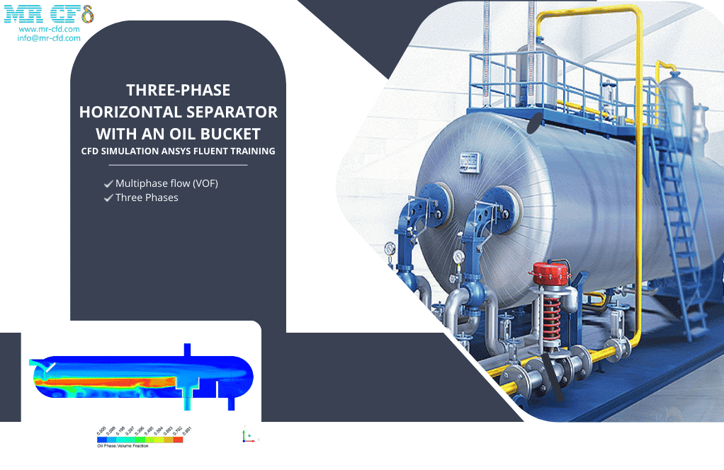
In this project, a 3-Phase Horizontal Separator with an Oil Bucket is simulated.
Click on Add To Cart and obtain the Geometry file, Mesh file, and a Comprehensive ANSYS Fluent Training Video.To Order Your Project or benefit from a CFD consultation, contact our experts via email ([email protected]), online support tab, or WhatsApp at +44 7443 197273.
There are some Free Products to check our service quality.
If you want the training video in another language instead of English, ask it via [email protected] after you buy the product.
Description
Separator Problem Description
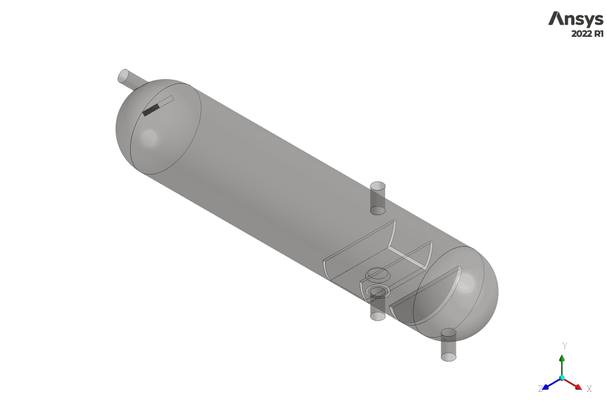
The 3-Phase Horizontal Separator works based on the density differences of fluids. The mixture of fluids inter through the inlet vessel and, after collision with the inlet diverter, enters the tank. In reality, the Separator is equipped with sensors to control oil and water level and then control mass flow.
Therefore, controlling the mass flows is a challenge in the simulation. In this project, the density of air, water, and oil is assumed to be 1.2, 998 & 689 kg/m^3, respectively. Also, the VOF Multiphase model is used.
Geometry & Mesh
The 3D geometry is modeled in Ansys Design Modeler software. A cylindrical zone with a 1m diameter extended for 8 meters with two caps. Also, the mesh grid is carried out using Ansys Meshing software.
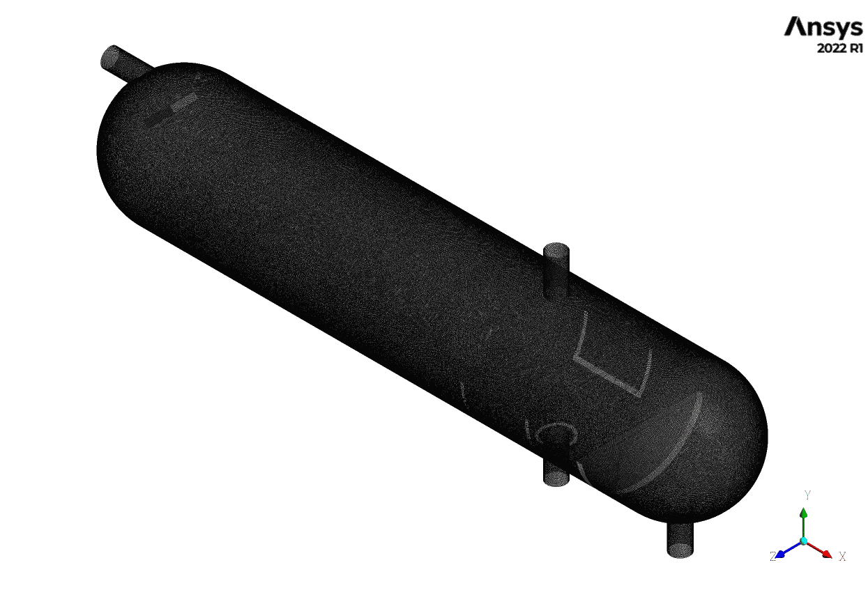
Furthermore, an unstructured grid is generated, and in total, 7166267 elements established the fluid domain, which is depicted in the following figure.
CFD Simulation
Several assumptions have been considered to simulate the horizontal 3-phase separator, including:
- The simulation is steady.
- The pressure-based solver type is used due to the incompressibility of the working fluids.
- Gravitational acceleration effects are applied in the y-direction.
The following table represents a summary of the solution:
| Models(Viscous) | ||
| Viscous | K-epsilon | Realizable |
| Multiphase | Type | VOF |
| Formulation | Implicit | |
| Primary Phase
Secondary Phase Secondary Phase |
Air
Oil Water-liquid |
|
| Materials | ||
| Fluid | Definition method | Fluent database |
| Material name | Air | |
| Engine-oil | ||
| Water-liquid | ||
| Cell zone condition | ||
| Material name | Mixture-template | |
| Boundary condition | ||
| Inlet | Type | Mass-flow-inlet |
| Gas-phase | 0.005 kg/s | |
| Oil-phase | 2 kg/s | |
| Water-phase | 3 kg/s | |
| Outlet-gas
Outlet-oil
Outlet-water
Wall-shell Oil-Bucket Diverter Separator |
Type | Mass-flow-outlet |
| 0.005 kg/s | ||
| Type | Mass-flow-outlet | |
| 2 kg/s | ||
| Type | Mass-flow-outlet | |
| 3 kg/s | ||
| Type | Wall
(Stationary – No-slip condition) |
|
| Solver configuration | ||
| Pressure-velocity coupling | Scheme | Coupled |
| Spatial Discretization | Gradient | Least squares cell-based |
| Pressure | PRESTO! | |
| Momentum | First-order upwind | |
| Volume Fraction | Modified HRIC | |
| Turbulent kinetic energy | First-order upwind | |
| Turbulent dissipation rate | First-order upwind | |
| Initialization | Initialization methods | Standard Initialization |
| Run Calculation | ||
| Number of time steps | 1000 | |
Separator Results
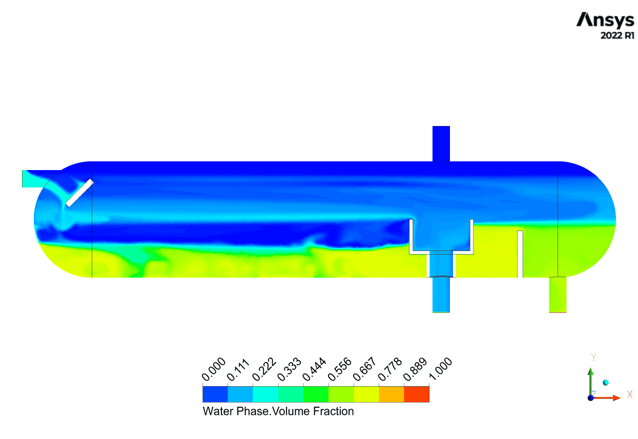
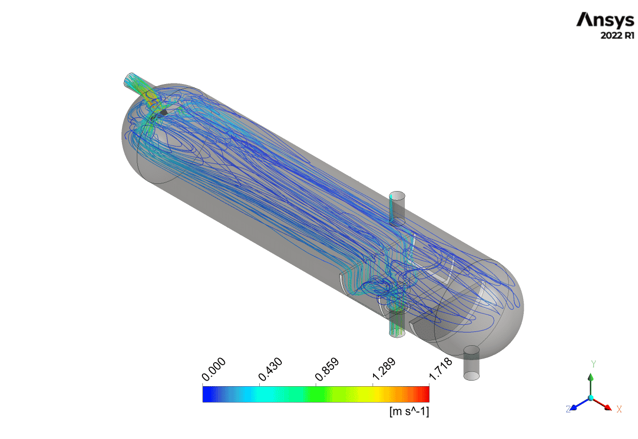
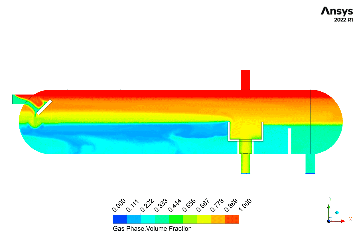
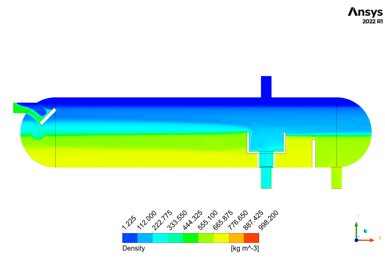
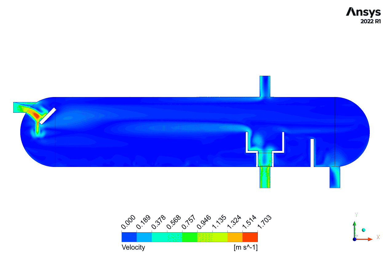
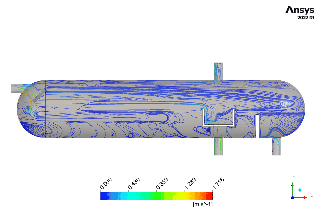
After the simulation process, the two & three-dimensional contours are extracted. It is evident that high inlet velocity could increase the mixing rate, which is not our interest and aim. So by using an inclined diverter, the velocity decreases and enters the fluid domain.
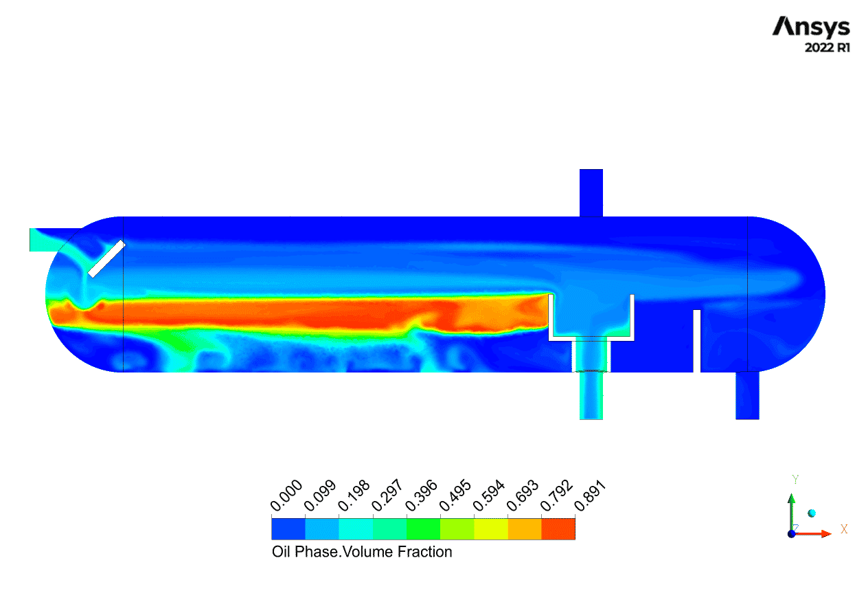
Due to the density gradient, the dense fluid (water) remains at the bottom of the tank, and the oil on the top reaches the oil bucket level and leaves the tank. The volume fraction contours corroborate the claim.

Cayla Bernhard –
The training for the Separator CFD was top-notch! It was impressive to see how different fluid densities were handled and how the separators’ performance was optimized. Thanks for such detailed content.
MR CFD Support –
Thank you for your kind words! We’re glad to hear that you found the Separator CFD Simulation training to be impressive and informative. It’s wonderful to know that the details we provided on fluid handling and performance optimization were helpful. Your positive feedback inspires us to keep delivering high-quality learning experiences. If you have any more questions or need further assistance, feel free to reach out!
Dr. Demarco McGlynn –
The training material on 3-Phase Separator simulation was incredibly detailed. The explanation of different phases and their properties was clear. The divergence using the inclined diverter and the successful simulation of density-based separation was presented effectively. The use of images to visualize the mesh and the contours helped to understand the process beautifully. Great job on elucidating the results with clarity.
MR CFD Support –
Thank you for your positive feedback! We’re glad to hear that the material was helpful and that the imagery enhanced your understanding. This kind of validation motivates us to continue providing high-quality training content. If you have any more questions or need further learning materials, please don’t hesitate to reach out.
Camylle Glover –
I’m so impressed with the thorough analysis and clear explanations in this training product. It’s great how the separation is demonstrated using real product conditions and the illustrations help to visualize the process effectively.
MR CFD Support –
Thank you for your positive feedback! We’re delighted to hear that our product successfully conveys the intricate details of the separator simulation and assists you in visualizing the scenario effectively. We always strive to offer clear and comprehensive educational materials. If you have any further questions or need assistance, don’t hesitate to reach out.
Evie Lang Jr. –
I see in the simulation you had different mass flow rates for air, oil, and water. How did controlling these different mass flows affect the outcome of the simulation?
MR CFD Support –
In our Separator CFD Simulation, we carefully controlled the mass flow rates for each substance to mimic the operational conditions of a physical 3-Phase Horizontal Separator. The appropriate flow rates for air, oil, and water are crucial for accurately predicting how these phases will separate given their density differences. By setting the correct inflow rates – air at 0.005 kg/s, oil at 2 kg/s, and water at 3 kg/s – and utilizing mass-flow-outlet boundary conditions, we could observe the fluid behaviors and separation accurately. The volume fraction contours showed that the denser water settled at the bottom while the less dense oil floated to the top, which is the desired outcome. Adjusting these mass flow rates was essential to ensure that the fluids would separate effectively within the simulation; deviations might alter the separation efficiency and quality represented in the results.
Ashlee Hilpert –
The simulation results look very thorough. The use of the inclined diverter to control flow and separate fluids based on density difference seems well thought out. Great representation of different phases and how they segregate!
MR CFD Support –
Thank you for your positive feedback! We’re pleased to hear that the simulation met your expectations and that the results were presented clearly. We always strive to offer comprehensive analyses with our CFD simulations. If there are any more specific details or simulations you are interested in, feel free to ask.
Delphine Weber –
The explanation was quite thorough, but could you provide more detail on how the wall boundary conditions affect the simulation results?
MR CFD Support –
The wall boundary conditions play a crucial role in simulating the behavior of fluids in the separator. They are set to a no-slip condition, which means there is zero velocity at the wall, to mirror the physical reality where fluid at the boundary has no relative motion to the wall. This impacts the flow behavior within the separator, influences the distribution and separation of the phases, and affects the overall simulation accuracy and predictive capability.
Mireya Johns –
Are the fluids mixed equally in the tank throughout the simulation, or is there an area inside the separator where one of the phases dominantly exists over the others?
MR CFD Support –
In the simulation of the 3-Phase Separator, the fluids are not mixed equally throughout the tank. Due to the density differences and gravity’s effect, the water, being denser, settles at the bottom of the tank, the oil due to being lighter than water but heavier than air floats on top of the water, and the air, being the least dense, stays on top. The volume fraction contours from the results clearly show this separation where each fluid phase predominantly exists within its designated area in the separator.
Lily Haley –
I’m considering this training for a project. Does it cover how to adjust the simulation parameters if the separator has to work with different fluid densities than those specified in the base model?
MR CFD Support –
Yes, the training will guide you through adjusting the simulation parameters to accommodate different fluid densities. It covers the fundamentals of setting up and running a multiphase flow simulation using the Volume of Fluid (VOF) model, which can be adapted to various fluid densities by changing the fluid properties in the ‘Materials’ section in ANSYS Fluent.
Ruben Kshlerin –
I found the project super interesting! The way the separation of different fluids based on density differences was detailed helped me grasp the concept better. Thank you for such a well-documented case study.
MR CFD Support –
Thank you for your kind words! We’re thrilled to hear that our case study has aided in your understanding of fluid separation in horizontal separators. Our goal is to provide clear and informative examples that help our customers. If you have further feedback or need more information, please let us know!
Rosalinda Bauch –
Regarding the initial assumptions, how does the assumption of steady simulation affect the accuracy given the complex interactions between oil, water, and air in a separator?
MR CFD Support –
The assumption of a steady-state simulation simplifies the analysis by considering that the flow properties within the separator remain constant over time. This can be a valid approximation if the interactions between oil, water, and air reach a consistent and stable pattern fairly quickly. However, if transient effects play a significant role, like slugs or surges, a transient simulation would be more accurate. Assuming steadiness is typically a compromise between computational resources and the desired accuracy.
Evelyn Bergstrom Jr. –
I appreciated the clear breakdown of boundary conditions and solver configurations in the Separator CFD simulation product, which allowed for efficient setup and execution of the simulation without any hitches. The inclusion of high-quality visualizations really helped grasp the complexity of multiphase flow behaviors in a horizontal separator.
MR CFD Support –
Thank you so much for your positive feedback! We’re thrilled to hear that the simulation’s detailed setup and high-quality visualizations met your needs and enhanced your understanding of multiphase flow in the separator. If you have any more questions or need further clarification, don’t hesitate to ask. We’re here to assist you.
Darron Berge III –
I am really pleased with how the separation process has been shown in the results. Excellent depiction of the working principle of a horizontal 3-phase separator.
MR CFD Support –
Thank you for your positive feedback! We are glad to hear that the presentation and results of the horizontal 3-phase separator simulation met your expectations and helped in understanding the separation process clearly. If you need further assistance or more detailed explanations about any aspect of our simulations, please don’t hesitate to reach out. We’re here to help!
Giovani O’Kon –
I loved how thorough the simulation was and the detail provided for various features like the deep-sea waves and the fish cage’s dynamics. The FSI approach seemed robust, and it was fascinating to see the interaction between the air, seawater, and structure. Can’t wait to see what other simulations this technology can handle!
MR CFD Support –
Thank you for your positive feedback! We are thrilled to hear you found the simulation thorough and compelling. MR CFD is always eager to push the boundaries of what’s possible with simulations using the latest technology and methodology. Your enthusiasm is highly appreciated, and we look forward to providing more insight into complex systems in future products.
Sydney Connelly –
The learning material seems detailed, but can you give me some more insight into how the initial conditions are determined for this kind of simulation?
MR CFD Support –
In this type of simulation, the initial conditions are usually based on physical properties, such as the densities, of the fluids involved along with typical operating conditions for the equipment. Real-world measurements and empirical correlations may help to set these initial conditions accurately to ensure that the simulation outcomes reflect a probable scenario. Additionally, engineers may run preliminary simulations to adjust the initial conditions for better convergence and physically realistic results.
Tracey Hodkiewicz –
Very pleased with the Separator CFD Simulation training! The realizable K-epsilon model inclusion provided an excellent grasp of handling a turbulent flow for multiphase simulations. Practical understanding of the gravitational effects within the tank broadened my comprehension substantially!
MR CFD Support –
Thank you for the positive feedback! We’re thrilled to hear that the Separator CFD Simulation training has been helpful for you and that you’ve gained valuable knowledge on dealing with turbulent multiphase flows. Your appreciation means a lot to us, and we’re here for any further guidance you might need!
Prof. Noah Sporer –
Can this training be useful for understanding the separation process in a production environment, and is it suitable for beginners in CFD?
MR CFD Support –
Yes, this training provides a comprehensive understanding of the separation process using ANSYS Fluent and can be valuable for anyone involved in designing or analyzing such equipment in a production environment. The step-by-step approach taken in this training makes it suitable for beginners who are starting out with CFD analysis.
Christine Graham –
I’m extremely impressed with the challenges of simulating mass flows that were overcome in the 3-Phase Horizontal Separator project. Great to see advanced multiphase modeling tackled with precision!
MR CFD Support –
Thank you for your positive feedback! We are glad to hear that you appreciated the complexity and accuracy of the simulation in the 3-Phase Horizontal Separator CFD project. If you have more questions or need further details, don’t hesitate to ask!
Marlen Reynolds –
Thanks for the detailed explanation! I am impressed with how the simulation manages to control mass flows in such a complex system. The results seem very insightful, especially when analyzing the dynamics of multiphase flows within the separator. Great job on this one!
MR CFD Support –
Thank you for the positive feedback! We are glad to hear that you found the simulation results insightful and our explanation detailed. If you have any more questions or need further assistance, feel free to reach out to us. We’re here to help!