Gas Turbine Combustion Chamber 2-D CFD Simulation
$140.00 Student Discount
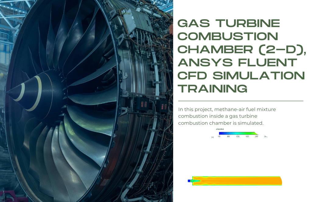
- In this project, methane-air fuel mixture combustion inside a gas turbine combustion chamber is simulated by ANSYS Fluent software.
- The geometry required for this analysis, which includes only the gas turbine injector part, is designed in ANSYS Design Modeler and mesh inside ANSYS Meshing.
- The mesh type used for this geometry is structured and the element number is 197006.
- the species transport model is used to analyze the combustion process by applying the Eddy Dissipation method.
- Simulation is done using a density-based solver.
To Order Your Project or benefit from a CFD consultation, contact our experts via email ([email protected]), online support tab, or WhatsApp at +44 7443 197273.
There are some Free Products to check our service quality.
If you want the training video in another language instead of English, ask it via [email protected] after you buy the product.
Description
Gas Turbine Combustion Chamber (2-D), ANSYS Fluent CFD Simulation Tutorial
This simulation is about a Gas Turbine combustion chamber via ANSYS Fluent software. We perform this CFD project and investigate it by CFD analysis.
A gas turbine is a rotating machine that operates on the energy of combustion gases. Each gas turbine includes a compressor to compress the air, a combustion chamber to mix the air with the fuel and ignite this mixture, and a turbine to convert the energy of hot and compressed gases into mechanical energy.
Part of the mechanical energy produced in the turbine is spent on turning the compressor itself, and the rest of the energy, depending on the application of the gas turbine, may spin the generator (turbo-generator), accelerate the air (turbojet and turbofan) or be used in other applications.
The fuel system in gas turbines is constantly changing, and engineers and designers in the field of mechanical engineering have tried to improve this important part of gas turbines.
The use of gas turbine injectors in the fueling section of gas turbines is one of the most important and, at the same time, efficient methods in this field. In this project, methane-air fuel mixture combustion inside a gas turbine combustion chamber is modeled.
Methane and oxygen are injected inside the combustion chamber with a velocity of 128.9304m/s and 12.0396m/s and temperatures of 286K and 109K, respectively.
The fuel mixture is then ignited, and energy and heat are generated. The geometry of the present model is drawn by Design Modeler software. The model is then meshed by ANSYS Meshing software. The model mesh is structured, and 197006 cells have been created.
Method
In this simulation, air and fuel enter the combustion chamber. So you have to define the species in the model. Therefore, the species transport model has been used. This model solves the transport equations of each defined species.
Also, the volumetric reaction should be used to define the combustion reaction. The Eddy-Dissipation method has been used to investigate the chemical-turbulent interaction of combustion reactants.
The real gas equation has also been used to determine the vapor’s density changes due to temperature changes.
Conclusion
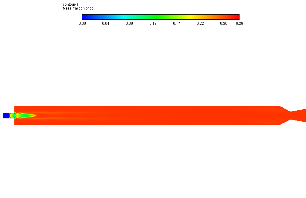
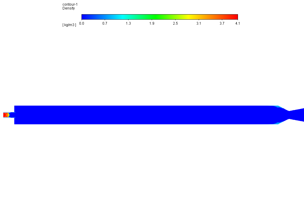
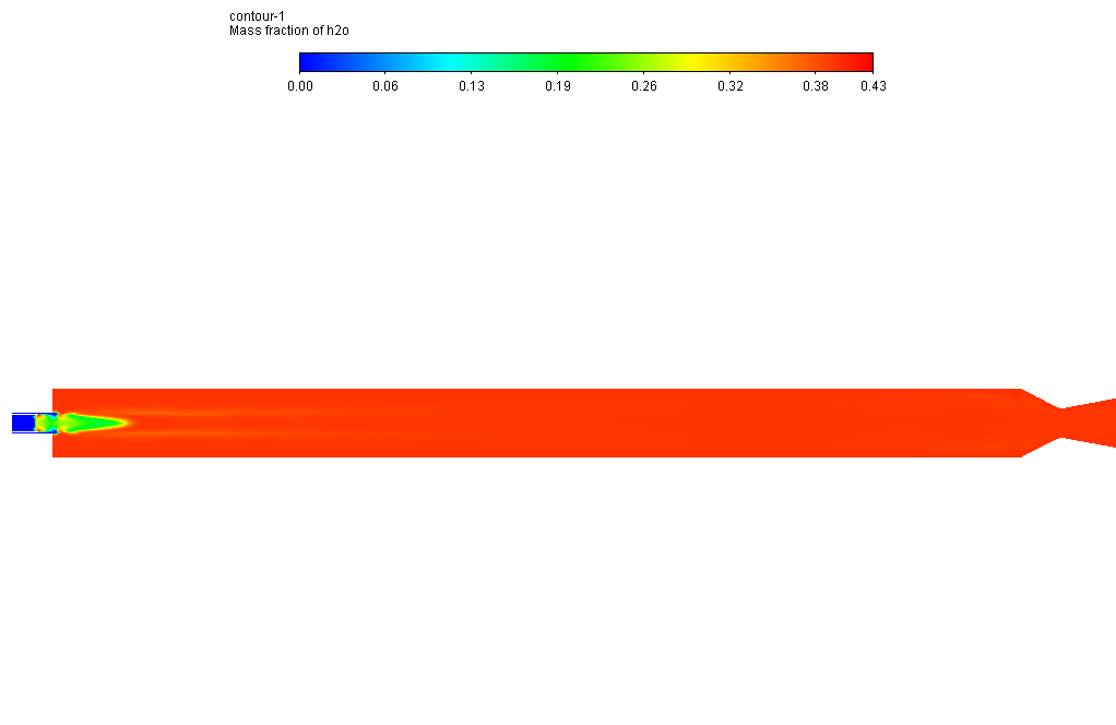
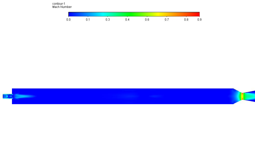
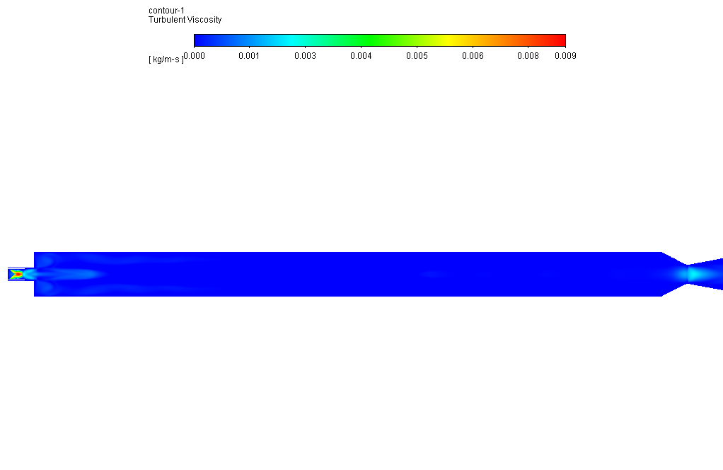
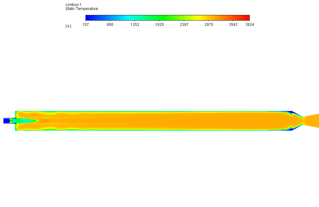
After simulation, the contours of each defined species’ temperature, velocity, pressure, and mass fraction are obtained. The results show that the combustion reaction occurred properly inside the combustion chamber.
The oxidizer and fuel are high at the inlet of the combustion chamber and then begin to fade because these are considered combustion reactants. On the other hand, H2O and CO are initially zero and then start to grow along the combustion chamber because these are considered combustion products.
Also, since the combustion reaction is exothermic, significant heat is generated inside the chamber, which helps to increase the temperature of the combustion chamber.

Pete King –
Can this simulation be customized to model different types of combustion chambers?
MR CFD Support –
Absolutely! We can modify the model to simulate different types of combustion chambers and different operating conditions. Please share more details about your requirements.
Prof. Ross Hintz –
I had never worked in modeling before; it was new to me.
Dr. Reanna Wolf I –
Your work is truly impressive. Keep it up!
Yoshiko Welch –
I’m impressed with how detailed the results are, showing the combustion process with the mass fraction contours and temperature distribution. Did the simulation also calculate the amount of emissions produced during the combustion?
MR CFD Support –
Thank you for your kind words! Emission calculations such as NOx, CO, and unburned hydrocarbons can be included in such simulations using additional models and reaction mechanisms available within ANSYS Fluent. However, as this detailed analysis was focused on the combustion reaction and temperature distribution, it was not specifically mentioned if emissions were calculated in this project. For precise emission analysis, one typically investigates with a reaction mechanism capable of predicting pollutant formation.
Mr. Zachary Kunze I –
I had a great time going through the Gas Turbine Combustion Chamber simulation tutorial! The level of detailed explanation made understanding the complex processes so much clearer. I particularly appreciated the comprehensive coverage on species transport model and the application of the Eddy-Dissipation method. Visualizing the temperature gradients and combustion products through the provided contours truly tied the theoretical aspects to practical observations.
MR CFD Support –
Thank you for your positive feedback! We are thrilled to hear that you found our Gas Turbine Combustion Chamber simulation tutorial informative and helpful. It’s great that the detailed explanations and visual elements enhanced your understanding of the species transport process and combustion dynamics. If you have any questions or need further clarification on any aspects of the simulation, please don’t hesitate to ask. We’re here to ensure your learning experience is smooth and rewarding!
Mrs. Lesly Mueller DVM –
How accurate is this simulation?
MR CFD Support –
Our simulations are based on well-established physical and mathematical principles. We also validate our simulations against experimental and theoretical results to ensure their accuracy.
Jeanne Goldner –
What method was used for the simulation to resolve the interaction between turblence and chemistry in the combustion process?
MR CFD Support –
In the simulation, the Eddy-Dissipation method has been used to investigate the chemical-turbulent interaction of combustion reactants within the gas turbine combustion chamber.
Prof. Alessandra Dickinson III –
The description is very thorough. Could you tell me how the Eddy-Dissipation method helps in investigating the chemical-turbulent interaction in the combustion process?
MR CFD Support –
In the context of this simulation, the Eddy-Dissipation method manages the interaction between turbulence and chemical reactions. Essentially, this approach assumes that the rate at which reactants combine is much faster than the rate at which turbulent eddies can bring reactants together. Thus, the overall chemical reaction rate is controlled by the rate of mixing caused by turbulence rather than by the kinetics of the molecular reaction. This simplification is particularly useful for modeling combustion where the chemical timescale is significantly shorter than the flow timescale.
Dr. Erik Crooks V –
What specific methods and models were selected in ANSYS Fluent for this gas turbine combustion simulation?
MR CFD Support –
The specific methods and models selected for this gas turbine combustion simulation in ANSYS Fluent included the use of the Species Transport model to manage the introduction of varying species into the combustion chamber, the application of the Eddy-Dissipation method for examining the interaction between chemistry and turbulence during the combustion, and the Real Gas model to address the density changes in the gas phase resulting from temperature variations.
Calista Johns –
Were different types of fuels considered and compared in this simulation, or was it solely focused on methane?
MR CFD Support –
For this particular simulation, we specifically focused on methane as the fuel for the gas turbine combustion chamber. Methane and oxygen were defined as the primary reactants in the combustion process.