
Stall Delay CFD Simulation of Bionic Airfoils: Paper Validation
$180.00 $108.00 HPC
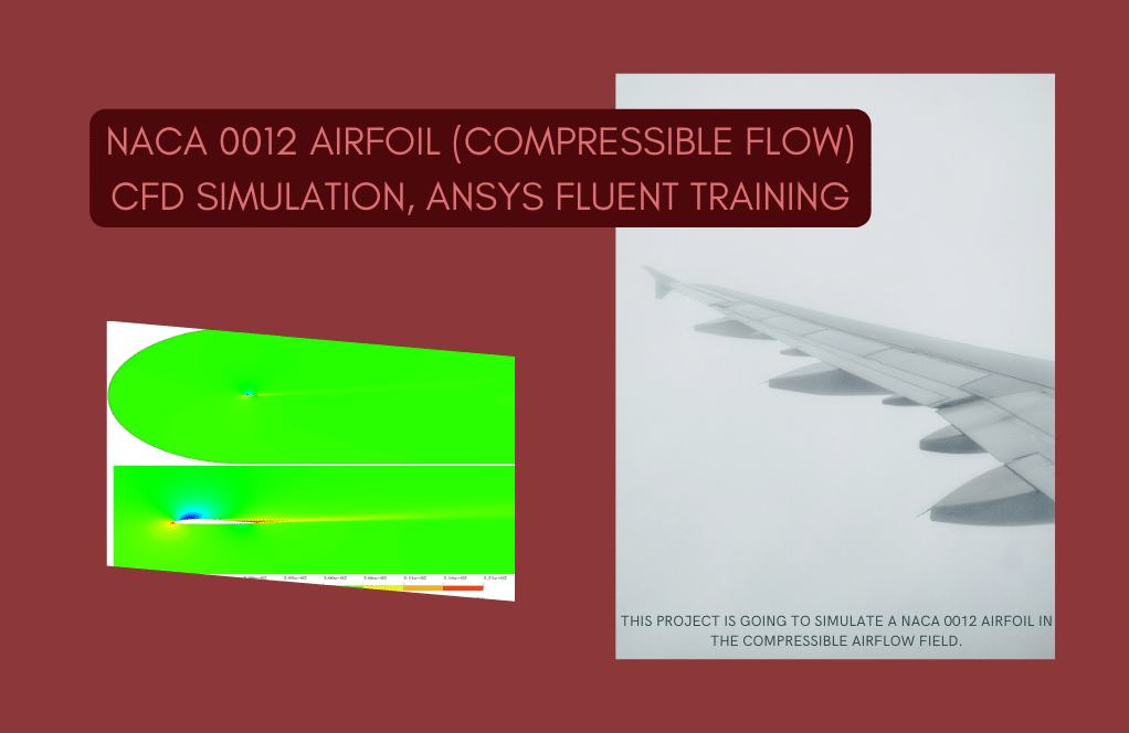
- The current CFD Analysis numerically validates the paper “Numerical and experimental investigation of bionic airfoils with leading-edge tubercles at a low-Re in considering stall delay” via ANSYS Fluent software.
- The geometry of a NACA 4415 baseline airfoil with leading-edge tubercles is designed in SpaceClaim and meshed in ANSYS Meshing, generating 7,291,791 elements which were later converted to polyhedrons for improved accuracy and reduced cost.
- The turbulence of the flow is modeled using the Realizable k-epsilon turbulence model, with steady-state simulations performed at angles of attack of 18°, 22°, and 26°.
To Order Your Project or benefit from a CFD consultation, contact our experts via email (info@mr-cfd.com), online support tab, or WhatsApp at +44 7443 197273.
There are some Free Products to check our service quality.
If you want the training video in another language instead of English, ask it via info@mr-cfd.com after you buy the product.
Description
Stall Delay CFD Simulation of Bionic Airfoils with Leading-Edge Tubercles at a low-Re: Paper Validation
Project Description
In Stall Delay project, we aim to simulate a bionic airfoil with leading-edge tubercles and validate the results with a numerical paper entitled “ Numerical and experimental investigation of bionic airfoils with leading-edge tubercles at a low-Re in considering stall delay “. The target parameter is the lift coefficient at 18, 22 & 26 angles of attack.
CFD Simulation
The geometry is designed in SpaceClaim software. The baseline airfoil is NACA 4415 with a mean chord of 100mm, and the span of all airfoils is 160mm. After that, the mesh grid is generated via ANSYS Meshing software. The first layer thickness of the boundary layer is the critical parameter because, due to turbulence effects and requirements of turbulence models, the Y-plus on the airfoil surface should be below 1. As a result, 7291791 tetrahedron cells were generated and then converted to polyhedron cells to reduce computational costs and increase quality. (check the figures below)

Figure 1- Y-plus on NACA 4415 airfoil – AOA 18
The pressure-based solver type is used due to the incompressibility of the working fluid. Also, the simulation is performed in steady-state form. In addition, the best convergence is achieved by the K-epsilon Realizable turbulence model, which accurately models eddy turbulence and wakes.
Results
After the convergence, 2d contours were extracted, and the lift coefficient is reported. As seen in the table and plot below, in 18, 22 & 26 degrees AOA, the error is 14.4%, 12.4% & 6.97%, respectively, below 15%.


Also, velocity and pressure contours are depicted below to understand better fluid behavior in different angles of attack around the airfoil. The flow separation on the suction side is clearly visible in velocity contours.

Figure2. Pressure distribution around the airfoil a) AOA 18 b) AOA 22 c) AOA 26

Figure 3- Velocity vectors at 26 AOA

Figure 4- Velocity contours around the airfoil at a) AOA 18, b) 22 AOA, c) 26 AOA
You must be logged in to post a review.

Reviews
There are no reviews yet.