
ANSYS STRUCTURAL: L-Bracket Static Simulation
$180.00 Internship
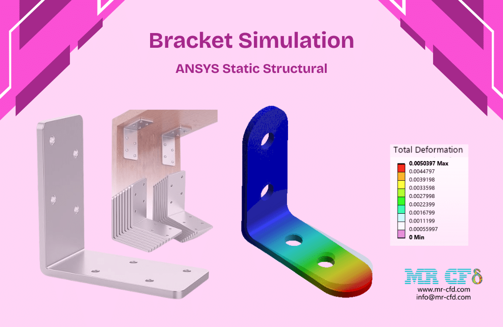
- This product simulates an L-Bracket using ANSYS Static Structural software.
- We model the 3D geometry with the Design Modeler software and mesh it as an unstructured grid.
- We use Fixed Support and Force Load as the boundary load conditions.
To Order Your Project or benefit from a CFD consultation, contact our experts via email (info@mr-cfd.com), online support tab, or WhatsApp at +44 7443 197273.
There are some Free Products to check our service quality.
If you want the training video in another language instead of English, ask it via info@mr-cfd.com after you buy the product.
Description
ANSYS Static Structural: L-Bracket Analysis under Force Load and Fixed Support
Description
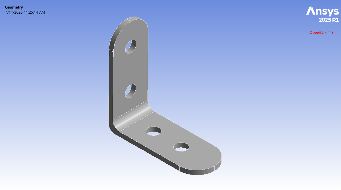
In this project, we present a structural simulation of a L-Bracket in ANSYS Static Structural.
A bracket is considered a supporting element utilized to connect, mount, or reinforce two separate pieces. It typically transfers load from one component to another while holding a component strongly in place. Brackets have many applications, widely used in shelving, piping supports, wall mounting, automotive and aerospace structures, and other general mechanical assemblies.
The Brackets are manufactured in several types, such as L-brackets, T-brackets, gusset brackets, and others. For this study, an L-shaped bracket is modeled. The L-bracket consists of two side plates joined at a right angle, which makes it appropriate for connecting perpendicular faces. So, these brackets are also called angle brackets or corner brackets. The main feature of the L-bracket is that it can resist bending phenomena at the junction between the two sides.
The goal of this study is to evaluate the structural response of the bracket under the force load, in the form of deflection and stress distributions.
Methodology
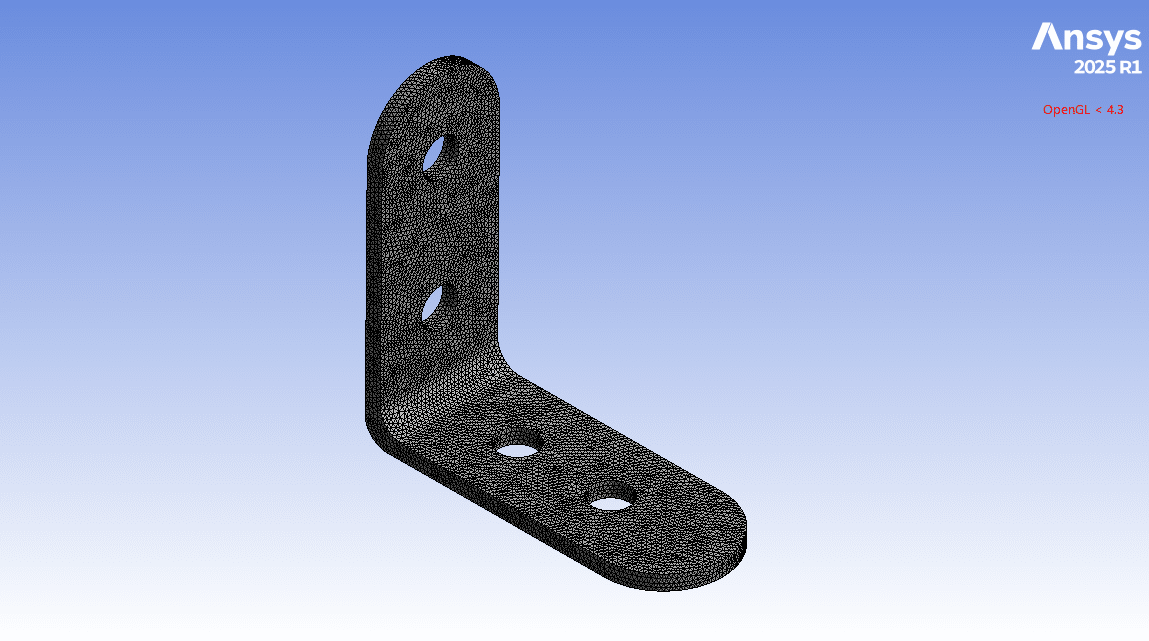
First, we modeled the geometry of the bracket with Design Modeler software. The computational domain corresponds to an L-bracket, which is made from two sides; each side contains two holes. Second, we meshed the domain; an unstructured mesh was created, generating about 155,800 elements. Finally, we completed the simulation and calculations with ANSYS Static Structural software.
We considered that the two holes on the vertical (standing) side are constrained, representing the bracket being bolted rigidly to a fixed base wall. In other words, it is treated as fully restrained. So, we used a fixed support condition for these holes, constraining all degrees of freedom.
On the other hand, two holes in the horizontal (seated) side are exposed to a purely vertical downward force, representing the weight of a mounted component transferred into the bracket through its own bolts. So, we used a force load condition in the y-direction for these holes. In conclusion, this loading condition represents a component pressing down on the horizontal arm while the vertical arm stays bolted to a support.
As the material for this bracket, stainless steel is determined. Stainless steel is an appropriate material for manufacturing brackets.
Conclusion
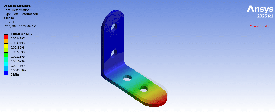
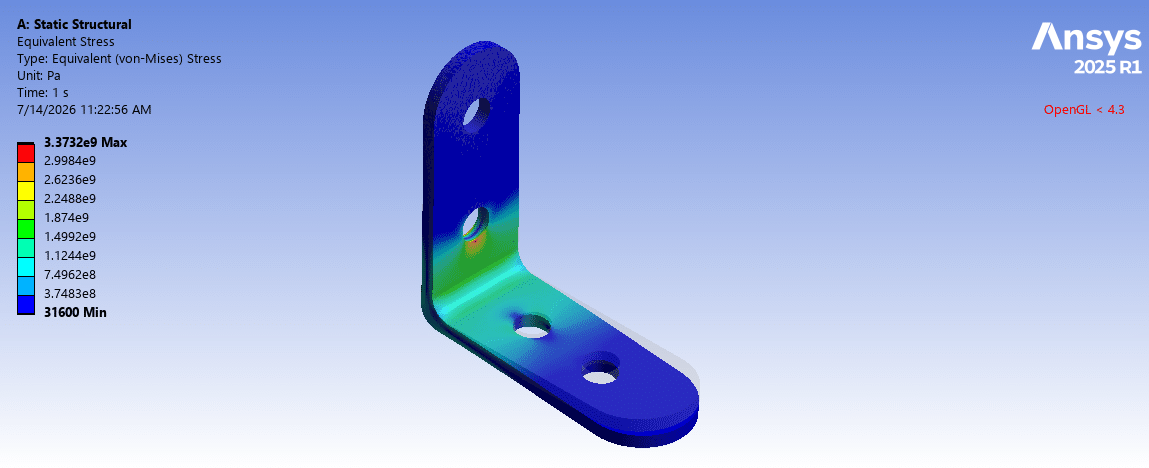
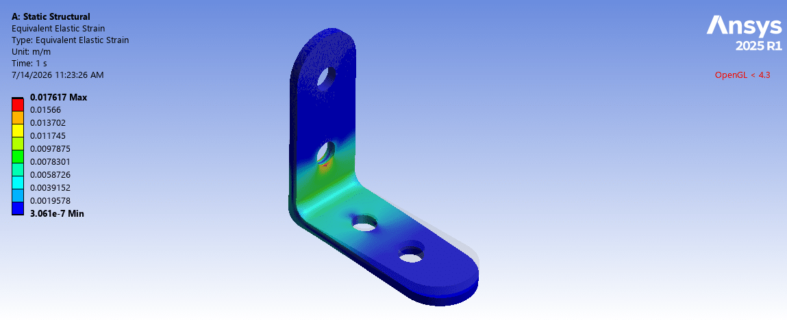
After the calculations, we obtained the contours of total deformation, equivalent strain, and equivalent (von Mises) stress over the bracket. The results are fully consistent with the behavior of an L-bracket under a downward load.
The total deformation distribution shows that the highest deflection occurs on the horizontal side of the bracket, where it is exposed to force loads. Since forces are applied downward to horizontal holes, downward displacement occurs. As you can see, the maximum deflection at the L-bracket occurs at the farthest position from the fixed holes, which are bolted on the vertical side.
The stress distribution indicates that the highest stress appears adjacent to the inner corner of the L-bracket. This is because this region experiences the largest bending moment. Note that the von Mises stress is concentrated around the bolted fixing hole.
You must be logged in to post a review.

 Talk On WhatsApp
Reviews
There are no reviews yet.