
ANSYS STRUCTURAL: Shaft Static Simulation
$180.00 Internship
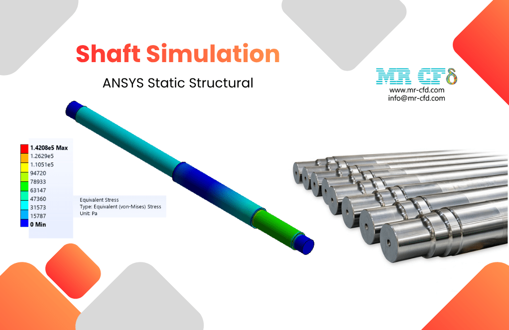
- This product simulates a Shaft using ANSYS Static Structural software.
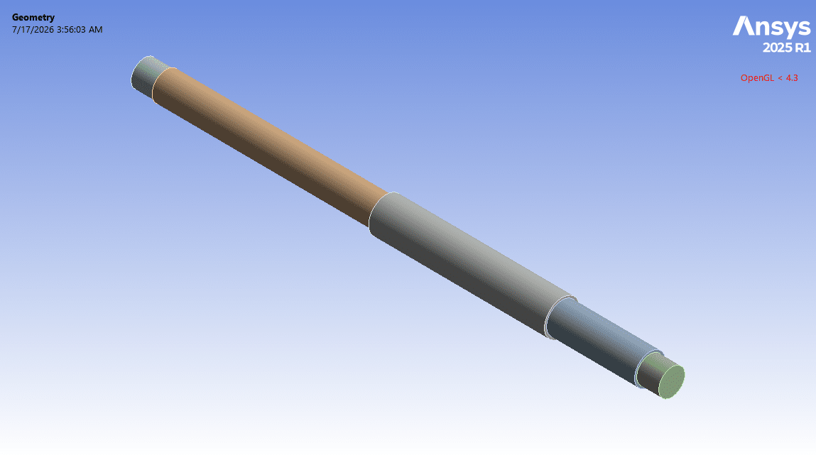
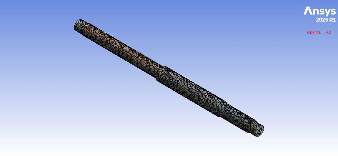
- We model the 3D geometry with the Design Modeler software and mesh it as an unstructured grid.
- We use Fixed Support and Moment Load as the boundary load conditions.
- The moment load is defined over time (loading and unloading).
To Order Your Project or benefit from a CFD consultation, contact our experts via email (info@mr-cfd.com), online support tab, or WhatsApp at +44 7443 197273.
There are some Free Products to check our service quality.
If you want the training video in another language instead of English, ask it via info@mr-cfd.com after you buy the product.
Description
ANSYS Static Structural: Shaft Analysis under Moment Load and Fixed Support
Description
In this project, we present a structural simulation of a shaft in ANSYS Static Structural.
A shaft is a rotating element in machinery systems used to transmit power and torque from one component to another. For example, a shaft is utilized between a motor and a gear or pulley. Shafts are one of the principal components in rotating devices, such as gearboxes, pumps, compressors, turbines, and automotive drivetrains.
There are several types of shafts. One of the most widely used is the stepped shaft, which is analyzed in the present study. In the stepped shaft type, the diameter varies along its length in the form of steps, so that different sections can seat bearings or gears, with different sizes.
The goal of this study is to evaluate the torsional response of the shaft under the moment load. The structural analysis of the shaft is important to ensure that the shaft operates in a safe and strong condition.
Methodology
First, we modeled the geometry of the shaft with Design Modeler software. The computational domain corresponds to a stepped circular shaft. This shaft is a long cylinder composed of four coaxial cylindrical segments but having different sizes. Second, we meshed the domain. As a result, an unstructured mesh was created, generating about 20,000 elements. Finally, we completed the simulation and calculations with ANSYS Static Structural software.
We considered that the two end cylindrical segments are the journals that would normally sit inside bearings. These bearings hold the shaft in place without any freedom of motion while allowing the rest of the shaft to carry the applied torque. Therefore, we defined fixed support conditions for these ends.
The middle segments represent the main body of the shaft where gears or other power-transmitting elements would be mounted. We considered that the load is applied as a moment (torque) on the shaft body, representing the twisting action delivered by a gear. So, we defined a moment load condition about the central axis of this shaft.
Note that the moment load is time-varying: it starts from zero up to a maximum value and then returns to zero. So, it reproduces a single loading–unloading cycle.
Conclusion
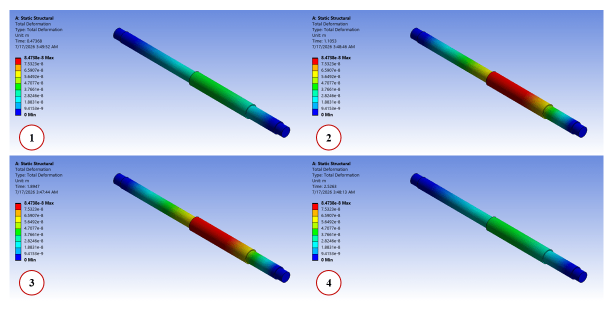
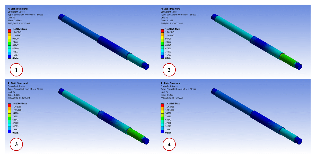
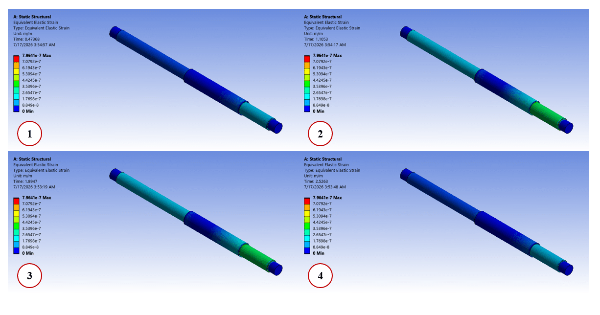
After the calculations, we obtained the contours of total deformation, equivalent strain, and equivalent (von Mises) stress over the shaft body. We studied these deformation and stress distributions over time (from loading to unloading).
The total deformation distribution shows that maximum angular deflection occurs on the loaded middle segment of the shaft, while the two ends stay fixed. Since a torque load is applied at the middle of the shaft body and both ends are held, the shaft twists on both sides of the loaded section. So, this deformation distribution is reasonable and consistent with the behavior of a shaft fixed at both ends and loaded in between.
The stress distribution indicates that the highest stress appears near the fixed supports, where the bending moment is highest.
In addition, the results show that after loading the moment on the shaft, deformation and stress increase; however, after unloading the moment, the increase in deformation and stress stops.
You must be logged in to post a review.
 Talk On WhatsApp
Reviews
There are no reviews yet.