Axial Flow Compressor (Rotor NASA 37) Simulation
$120.00 Student Discount
- The problem numerically simulates Axial Flow Compressor using ANSYS Fluent software.
- We design the 3-D model by the Design Modeler software.
- We Mesh the model by ANSYS Meshing software, and the element number equals 278162.
- We use a Density-Based solver to define the compressible flow.
- We use Frame Motion to define rotational motion around compressor blades.
To Order Your Project or benefit from a CFD consultation, contact our experts via email ([email protected]), online support tab, or WhatsApp at +44 7443 197273.
There are some Free Products to check our service quality.
If you want the training video in another language instead of English, ask it via [email protected] after you buy the product.
Description
Axial Flow Compressor (Rotor NASA 37) CFD Simulation, ANSYS Fluent Training
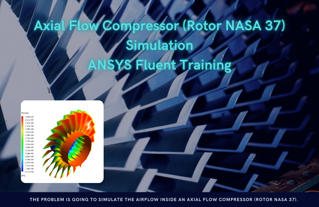
The problem is going to simulate the airflow inside an axial flow compressor (Rotor Nasa 37) by ANSYS Fluent software. We perform this CFD project and investigate it by CFD analysis.
The present model consists of a series of blades for an axial flow compressor connected to the central axis within a cylindrical area. To simplify the simulation model, only one row of rotating blades is drawn on the central rotor of the compressor.
The blades rotate around the central axis at a rotational speed of 14043 rpm. In addition, the mass flow rate of the air passing through the compressor is 33.25 kg/s.
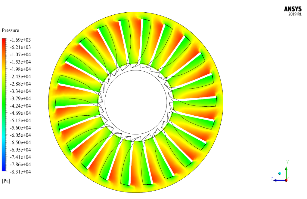
The purpose of this project is to investigate the behavior of airflow and the pressure distribution around the blades after compression by the compressor.
The present 3-D model is drawn using SOLIDWORKS software and then imported into the Design Modeler software. The meshing of the present model has been done using ANSYS Meshing software. The mesh type is unstructured and the element number is 278162.
Compressor Methodology
We have used the density-based solver due to compressibility.
To simulate the present model, the Frame Motion technique with the mentioned rotational speed has been used to simulate the airflow in the space around the compressor blades. So the blades are assumed to be fixed (without rotational speed), and the air around the blades has a rotational speed equal to the rotational speed of the compressor rotor.
Also, for the compressor blade wall, the boundary condition of the moving wall with zero rotational speed has been used compared to the surrounding area.
Compressor Conclusion
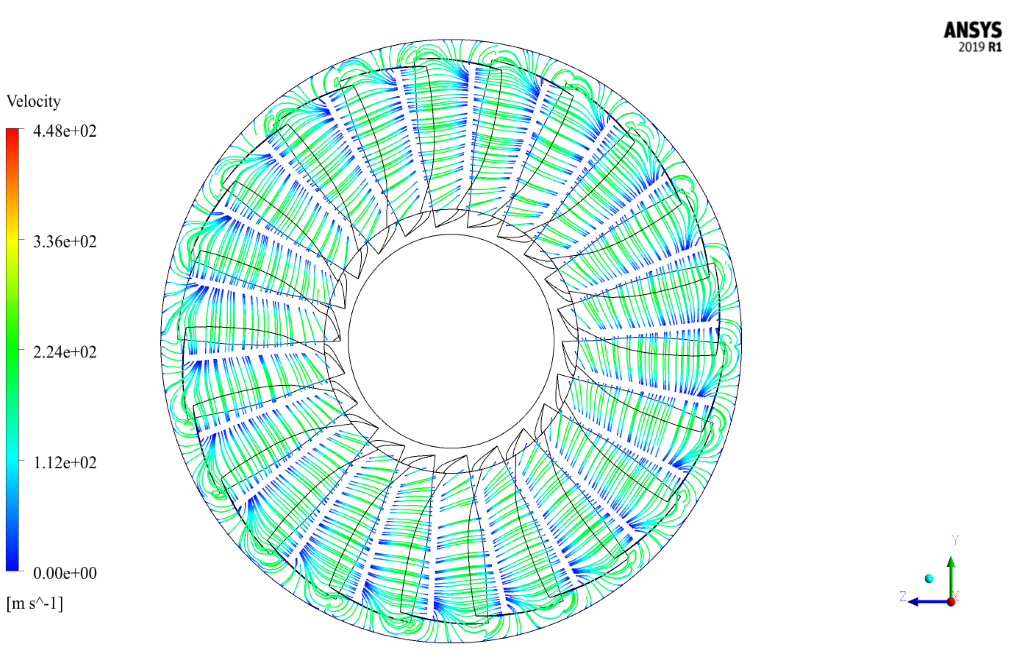
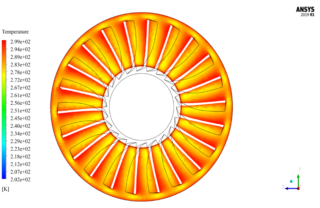
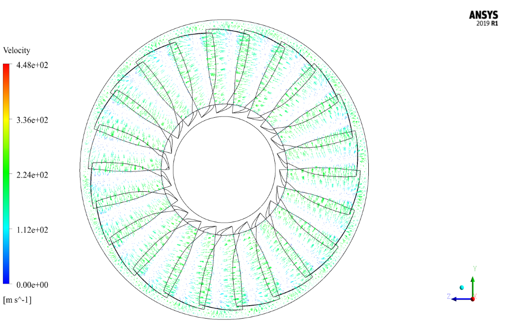
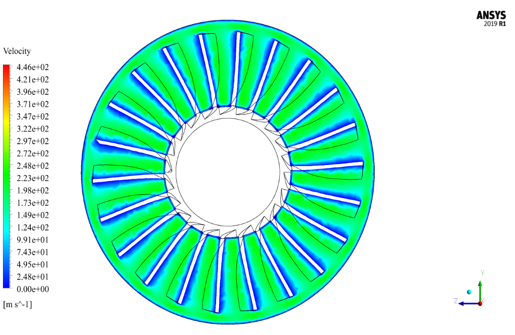
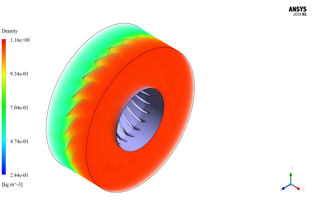
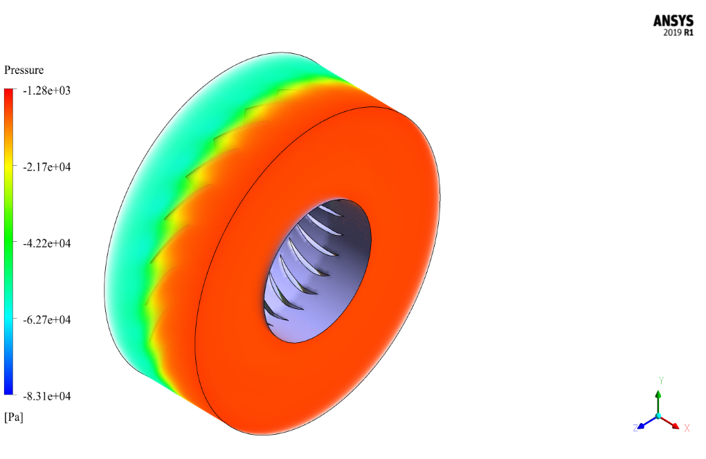
After the solution process, we obtain the two-dimensional and three-dimensional contours related to pressure, temperature, velocity, and density, as well as the two-dimensional and three-dimensional path lines and velocity vectors in the area for airflow around the compressor blades.
We obtain the two-dimensional contours and pathlines in the YZ section perpendicular to the direction of the compressor axis and in the position of the passage passing through the middle of the blades.
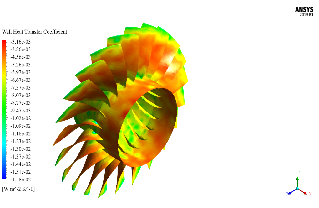
Also, we present pressure, temperature, and heat transfer coefficients on the body of the compressor blades.





Gaylord Daniel –
Excellent expressive power
Joel Lubowitz MD –
What is the main objective of this Axial Flow Compressor Rotor NASA 37 CFD Simulation?
MR CFD Support –
This simulation aims to analyze the performance of the NASA 37 rotor, a model of an axial flow compressor, which is a key component in many turbomachinery applications.
Alexys Konopelski –
Most of the advanced topics are covered in this project, and the person who prepares this course can be helpful to her.
Miss Janie Pacocha PhD –
This modeling of the axial flow compressor with the Rotor Nasa 37 looks impressive! The detail on the airflow dynamics and pressure distribution would be extremely helpful for understanding compressor behavior in realistic conditions.
MR CFD Support –
Thank you so much for your kind words! We’re delighted to hear that you find the detail on airflow dynamics and pressure distribution in our Rotor NASA 37 compressor simulation impressive and useful. Our goal is to provide comprehensive CFD simulations that aid in understanding complex behaviors in various engineering scenarios. If you have any more feedback or need further assistance, don’t hesitate to reach out!
Danyka Macejkovic Sr. –
This axial flow compressor simulation appears exhaustive. Was the tip clearance between the rotor blades and the compressor casing modeled in this simulation, and if so, what effect did it have on performance metrics like efficiency and stall characteristics?
MR CFD Support –
In our axial flow compressor CFD simulation, we included a detailed representation of the rotor-stator interaction, which also addresses the tip clearance effects. The tip clearance plays a significant role in the overall performance, leakage losses, efficiency and can also affect stall characteristics. Our analysis includes the consequences of these clearances, which are visible in the performance metrics extracted from our simulations.
Emelia Spencer III –
This course seems comprehensive! Can you provide information on how the temperature and compressibility effects are taken into account in the simulation?
MR CFD Support –
For this simulation of the axial flow compressor, the temperature and compressibility effects are taken into account using the density-based solver in ANSYS Fluent. This type of solver is well-suited for high-speed flows where density variations are significant due to changes in pressure and temperature. The complete Navier-Stokes equations are solved, ensuring that variations in temperature and pressure are captured accurately, which affects the density and behavior of the airflow around the compressor blades.
Dr. Clara Steuber –
The simulation work on the Axial Flow Compressor (Rotor NASA 37) seems incredibly detailed! Really appreciate how the methodology captures the physics of airflow and the pressure distribution, giving us a solid theoretical foundation to improve design. The clear visualization of contours and pathlines in the analysis also highlights the elegance of professional CFD. Great job to the MR CFD team!
MR CFD Support –
Thank you so much for your encouraging feedback! We are thrilled to hear that our detailed simulation and comprehensive methodology were helpful. It is always motivating for our team to receive such positive responses from our users. We strive to provide high-quality and accurate simulations to assist with design and analysis work. If there’s anything else you’d be interested in or need further assistance with, feel free to reach out. Looking forward to helping you with more projects in the future!
Prof. Tomasa Stoltenberg –
I just completed the Axial Flow Compressor CFD Simulation course and it blew me away! I’m very impressed by the detailed analysis and comprehensive training material that made complex concepts easier to understand. It was amazing to see the simulation results match so closely with theoretical predictions. The visualizations of airflow parameters were particularly enlightening. Great work on this training module!
MR CFD Support –
Thank you for your kind words and positive feedback! We’re thrilled to hear that you found the Axial Flow Compressor CFD Simulation course enlightening and that it helped you understand complex concepts more clearly. It’s always rewarding to hear that our efforts to provide detailed and comprehensive training materials have paid off. We appreciate your review and are glad that you’re impressed with the simulation results and visualizations. If you have any further questions or need more training, please feel free to reach out.
Ashly Moen –
I’m impressed with the sophisticated simulation of the axial flow compressor! How is the airflow ensured to maintain its mass flow rate during the simulation?
MR CFD Support –
Thank you for your positive feedback! Regarding your question, in the simulation, we ensure constant mass flow rate by applying boundary conditions that set the mass flow rate as an input parameter. In ANSYS Fluent, this can be done using the ‘mass flow inlet’ or similar boundary conditions defining the specific mass flow rate that the simulation must adhere to throughout the process.
Ms. Estella Kirlin –
Great detail in the workflow. Does this training course provide any supplementary materials such as tutorials for setting up my own simulations with different geometries?
MR CFD Support –
Thank you for your positive feedback! The training course focuses on guiding you through setting up the simulation for this particular compressor geometry. It includes comprehensive tutorials for using ANSYS Fluent, which should equip you with the necessary skills to set up your simulations involving different geometries. You can apply the concepts you learned to other relevant scenarios.
Prof. Hermann Schmidt –
This is an impressive evaluation of airflow within a compressor. I hope the simulation provides an accurate visualization of the pressure distribution which could be highly beneficial for design optimization in future development. Kudos for using high R.P.Msc which allows for comprehensive analysis.
MR CFD Support –
Thank you for your positive feedback! We strive to provide precise simulations that match practical scenarios as closely as possible, so your remarks on the evaluation of airflow and pressure distribution in our axial flow compressor simulation using ANSYS Fluent are much appreciated. We definitely hope our simulation contributes effectively to the optimization of compressor designs. If you require any further information or assistance, please feel free to reach out.
Alanna Shields DVM –
I’m very impressed with the detail level in the axial flow compressor simulation you’ve described. Do the derived heat transfer coefficients on the blades take into account any temperature gradients or cooling systems within the compressor structure?
MR CFD Support –
Thank you for your kind words and for showing interest in our product! The heat transfer coefficients obtained in our simulation take into account the temperature gradients resulting from the interaction between the airflow and the compressor blades. However, for the sake of the simulation, it doesn’t include specific internal cooling systems within the compressor structure, as those would be based on additional complexities requiring an advanced setup within the CFD model.
Arnoldo Gulgowski –
I’ve been through a lot of CFD cases, and this compressor simulation stands out with its complex dynamics. Nicely done! I’m curious—has drag analysis been included in the report to estimate efficiency losses due to blade design?
Alan Lynch –
I’m blown away by the level of detail in the simulation of the NASA 37 Rotor! The visualization of air patterns must be impressive. Was it challenging calibrating the solver settings to achieve accurate results?
MR CFD Support –
Thank you for your compliment! Calibrating the solver settings is indeed a critical step in ensuring the accuracy of CFD simulations. Our team takes great care in adjusting and validating these settings to capture the complex flow characteristics accurately. We’re pleased to hear you appreciate our attention to detail.
Heber Monahan –
I was amazed by the clarity of your results in showing airflow behavior around the compressor blades. The pressure and temperature variations are particularly well-presented. It was also educational to see the impact of the rotating blades on the flow field, aiding in the understanding of compressor operations. Your training made the complex concepts very accessible. Great work!
MR CFD Support –
Thank you so much for your positive feedback. We are thrilled to hear that our CFD simulation on the Axial Flow Compressor (Rotor NASA 37) was able to provide you with clear and comprehensible results, and that our training helped enhance your understanding of compressors. If you have any more questions or need further information, please don’t hesitate to reach out. We always strive to assist enthusiasts like you in grasping complex engineering concepts.
Dr. Isabel Bogisich II –
The training for the Axial Flow Compressor simulation looks super detailed and comprehensive! I can see how the use of a density-based solver and Frame Motion technique for air with adjusted rotational speed would provide highly accurate data regarding airflow behaviors. The point on achieving realistic pressure, temperature, velocity, and density contours and vector fields demonstrates the high-quality level of simulation that ANSYS Fluent facilitates. Great job!
MR CFD Support –
Thank you for your wonderful feedback! We’re thrilled that you recognize the detail and depth of the Axial Flow Compressor CFD simulation training. Our goal is to provide realistic and comprehensive analyses that can really aid understanding of complex fluid dynamics, and it’s fantastic to hear that you appreciate the effort put into using accurate methodologies and techniques. If you have any further questions or need more information, feel free to ask!
Prof. Johnpaul Huels Jr. –
I recently completed a project using your Axial Flow Compressor CFD Simulation and found the process very enlightening. The visualization of pressure and temperature distribution on the compressor blades was particularly impressive and helped me understand the effectiveness of my design. The mesh quality was top-notch. Excellent work!
MR CFD Support –
Thank you for your positive feedback! We’re delighted to hear that our CFD simulation of the Axial Flow Compressor was enlightening and beneficial for your project. It’s great to know that the visualization capabilities helped in understanding the design’s effectiveness. We always aim to provide high-quality meshes and simulations to assist our customers in their analysis. If you have any more inquiries or need further assistance with future projects, do not hesitate to reach out to us. Thank you for choosing MR CFD for your simulation needs!
Dillan Weimann IV –
The training material on Axial Flow Compressor (Rotor NASA 37) was exhaustive and explicit. Visualizing the pressure distribution and airflow behavior post-compression offered insightful understanding of the complex dynamics involved. Superb delineation of methodology and results!
MR CFD Support –
Thank you for your positive feedback! We’re delighted to know the simulation and accompanying information met your needs and provided clear insights into the axial flow compressor dynamics. If you have any further questions or interest in other simulations, please feel free to reach out.
Jolie DuBuque –
I’m impressed by the detailed analysis of airflow in the NASA 37 rotor axial flow compressor simulation. Great job in explaining the methodology and the results obtained.
MR CFD Support –
Thank you for your kind words! We’re delighted to help expand CFD knowledge and understanding. Your appreciation means a lot to us, and we’re pleased that our detailed analysis met your expectations.
Prof. Dewayne Hahn I –
This simulation sounds very technical! Could you clarify if any additional physical models, like turbulence modeling, were applied and, if so, which models?
MR CFD Support –
Yes, turbulence models play a crucial role in accurately simulating airflow behavior around compressor blades. In this particular simulation, a turbulence model was implemented to resolve the complexities of the turbulent airflow. By analyzing various turbulence models available, we selected a suitable one that matches the physics of the compressible airflow over the blades to ensure the simulation results reflect the real-world performance of the axial flow compressor effectively.
Prof. Jamaal Kuhn –
It was good; I think that was enough I could use.
Cullen McClure –
The simulation results seem in-depth! I’m curious though, how are heat transfer coefficients calculated for air flows in the compressor blades?
MR CFD Support –
Hello! The heat transfer coefficients in airflow around compressor blades are typically determined by calculating the local convective heat transfer between the air and the blade surface. This involves using numerical methods incorporated in ANSYS Fluent software to solve the heat transfer equations, considering factors such as airflow velocity, temperature gradients, and blade material properties. The software applies energy conservation equations in conjugation with fluid flow equations to compute the heat transfer coefficients with high precision in various regions of the compressor blades.
Daphney Bashirian –
The tutorial for the Axial Flow Compressor simulation was great! The step-by-step guidance made it clear how to set up and solve such a complex flow problem. The detailed insight into pressure and temperature distribution was really valuable for understanding compressor blade performance. Nicely done!
MR CFD Support –
Thank you for your compliment and I’m glad to hear that our Axial Flow Compressor simulation tutorial met your expectations! If you have any further questions or need more information on similar projects, please do not hesitate to reach out. We’re here to help!
Prof. Lelah VonRueden Jr. –
The training looked extremely informative! I’ve really understood better how to use Frame Motion and the results I can obtain with density-based solvers because of it.
MR CFD Support –
Thank you for your positive review! We’re delighted to hear that our training on axial flow compressors using ANSYS Fluent was informative and helped enhance your understanding of Frame Motion and density-based solvers. If you ever have more questions or need further assistance, feel free to reach out. Your success is our success!
Casper Mayert IV –
I am impressed with the detailed analysis of the airflow and pressure distribution around the blades of the NASA 37 Rotor using ANSYS Fluent software. The use of a frame motion technique to simulate the rotating blades is innovative, and obtaining velocity vectors in addition to pressure and temperature contours provides comprehensive and understandable data.
MR CFD Support –
Thank you for your positive feedback! We are glad to hear that our detailed approach and the innovative frame motion technique used for the axial flow compressor simulation provided you with comprehensive results. Your acknowledgment of the quality and clarity of our CFD analysis is highly appreciated. If you have any further questions or require additional information on our products or services, please don’t hesitate to reach out.
Jeromy Donnelly –
The Axial Flow Compressor simulation seems very detailed. Can you tell me what kind of post-processing would help visualize blade loading and stall margins?
MR CFD Support –
For visualizing blade loading and stall margins, pressure distribution plots on the blade surfaces can depict the loading. Additionally, examining parameters such as the streamlines, velocity vectors, and total pressure along different chord locations on the blades can identify the onset of stall. Furthermore, animations depicting the flow field around the blades during operation can help to understand the flow behavior and potential separations leading to stall.
Douglas Littel Sr. –
I’m highly impressed with the detailed simulation of the NASA 37 axial flow compressor. The insights into airflow behavior and pressure distributions provide valuable information for aerospace studies and applications.
MR CFD Support –
Thank you so much for your positive feedback on the NASA 37 axial flow compressor simulation! We’re really pleased to hear that you found the detailed analysis and results valuable for aerospace applications. If you have any further questions or need assistance with other simulations, feel free to reach out.
Layla Daniel –
I found the simulation details fascinating! Could you briefly explain how the airflow behavior differs from the inlet to the outlet of the compressor?
MR CFD Support –
The airflow behavior in an axial flow compressor like Rotor NASA 37 undergoes significant changes from inlet to outlet. As the air passes through the rotating blades of the compressor, it is compressed, gaining pressure and temperature while velocity gradients may develop due to the blades’ aerodynamic design. Outcomes typically include an increase in air density and a staggered pressure distribution around the blades, contributing to the overall compression effect that axial compressors are known for. The detailed simulation results provide insights into these changes, showing how effectively the compressor achieves the compression of airflow along its path.
Sharon Jones II –
The simulations and explanations were extremely clear. Viewing the detailed airflow behavior of the axial flow compressor provided deep insights into design and operation of such machinery.
MR CFD Support –
Thank you for your positive feedback! We’re delighted to hear that our simulation and explanations helped you understand the complex airflow dynamics in an axial flow compressor. If you have any more questions or need further assistance, don’t hesitate to reach out. Your interest and support motivate us to keep providing high-quality simulations and in-depth analysis.
Athena Gislason –
What type of flow simulation was used in the Axial Flow Compressor analysis, and why was it chosen?
MR CFD Support –
A density-based solver was used to perform the simulation because the compressibility effects are essential in a high-speed flow such as the airflow in the axial compressor, particularly at higher Mach numbers near or above 0.3 where the density variations become significant.
Dr. Astrid DuBuque V –
This course marvelousy explains the complexities involved in simulating the airflow in an axial compressor! The in-depth analysis helped clear my concepts on how frame motion technique is applied in such simulations.
MR CFD Support –
Thank you for your positive feedback on our Axial Flow Compressor (Rotor NASA 37) CFD Simulation training. It’s fantastic to hear that the course was able to enhance your understanding of frame motion techniques in CFD! We’re always here to help clarify complex concepts.
Danny Gorczany –
I’m highly impressed by the detailed investigation of airflow and pressure distribution in the Axial Flow Compressor simulation. The utilization of the Frame Motion technique to simplify the model while still delivering realistic results showcases outstanding expertise in employing CFD tools for complicated engineering challenges. Truly commendable work!
MR CFD Support –
Thank you so much for your kind words! We are glad to hear that you appreciate the complexity and the realism of the Axial Flow Compressor simulation. Our team goes to great lengths to ensure that our simulations provide accurate and valuable insights. Your feedback is extremely rewarding. If you have any further questions or need assistance with other products, we’re here to help!
Matt Labadie –
Can this simulation be used to optimize the design of an axial flow compressor rotor?
MR CFD Support –
Absolutely! The results from this simulation can provide valuable insights into the performance of the compressor rotor, which can be used for design optimization.
Fermin Dare III –
After finishing the course, my understanding of simulating rotational flow and mastering the density-based solver got significantly better—the visual representation made grasping complex concepts much easier.
MR CFD Support –
Thank you for your positive feedback! We’re thrilled to hear that our training on the Axial Flow Compressor simulation with ANSYS Fluent has enhanced your understanding of rotational flow and the use of the density-based solver. Your success with mastering these complex concepts is exactly what we aim for with our courses. If you need further assistance or have additional questions in the future, please feel free to reach out.
Mr. Bernard Torp I –
I’m impressed by the detailing in the Axial Flow Compressor CFD Simulation using ANSYS Fluent. The simulation outcomes like extending from pressure to heat transfer coeficients are critical for any aero-engineerinig application. Truly insightful and useful training material!
MR CFD Support –
Thank you for your kind words! We’re delighted the Axial Flow Compressor simulation details met your expectations and that you found the results from our CFD analysis insightful for aerospace engineering application. Your feedback is appreciated and encourages us to maintain our high standards in all our training materials!
Mr. Uriel Bins –
The description of the airflow behavior around the blades was particularly fascinating. Great work on demonstrating the effects of compression!
MR CFD Support –
We’re thrilled that you appreciated the detailed analysis of the airflow behavior around the blades in our Axial Flow Compressor simulation. Thank you for your positive feedback!
Prof. Daphnee Mayert –
The results showcase detailed airflow behavior around the compressor blades, but it’s not mentioned whether the simulation takes into account the tip clearance effect of the blades. Does the model incorporate blade tip clearance, which is a crucial factor in actual compressor performance?
MR CFD Support –
In this simulation, it is not specified if the effects of tip clearance have been taken into account. However, in real-world applications, tip clearance can indeed impact compressor performance significantly by influencing leakage flows and efficiency. For an accurate representation, it’s generally important to model the tip clearance in the simulation.
Judd Walsh II –
I loved droning through the extensive depictions given on airflow dynamics over the NASA 37 rotor. The images vividly captured the acceleration due to blade curvature and boundary layers. It was as if I could feel the rush of compressed air. Thank you MR CFD for a fantastic learning journey!
MR CFD Support –
We’re thrilled to hear that our Axial Flow Compressor (Rotor NASA 37) CFD simulation has provided you with a comprehensive and enjoyable learning experience. Thank you for your appreciation, and we look forward to delivering more educational content that fuels your enthusiasm!
Lawson Ebert –
The step-by-step details of your project make me confident to run similar simulations on my own. Great educational material!
MR CFD Support –
Thank you for your kind words! We are delighted to hear that our project details are helping you feel better prepared for your own simulations. If you have any further questions or need assistance, feel free to reach out!
Johan Hermiston –
The simulation description mentions a ‘density-based solver due to compressibility.’ Could you please clarify the benefits of using the density-based solver for this type of airflow simulation in the compressor?
MR CFD Support –
Absolutely, the density-based solver is utilized because it’s capable of handling compressible flows where density changes are significant—like in an axial flow compressor where air undergoes compression. The solver works well with high-speed flows and ensures accurate capture of shockwaves, offering clear benefits in terms of fidelity for pressure, temperature, and density predictions in compressible flow scenarios.
Brain Moore MD –
I found the detailed explanation of the airflow analysis around the compressor blades quite insightful. The CFD simulation results must be very accurate with such a well-defined model and methodology. Could you possibly share some highlights from the pressure distribution results?
MR CFD Support –
Thank you for your positive feedback on our Axial Flow Compressor CFD Simulation. We’re pleased to hear that you found the methodology thorough and insightful. Highlights from the pressure distribution results show a consistent increase in pressure across the blades, indicating efficient compression. The flow visualization also reveals a smooth transition of airflow with minimal turbulence, suggesting that the compressor’s design effectively manages the kinetic energies involved.
Lucas Satterfield MD –
The training seemed very comprehensive, but could you explain if a transient analysis was used too, or if it was only steady-state?
MR CFD Support –
The simulation of the NASA 37 axial flow compressor appears to have been conducted using a steady-state analysis rather than a transient one. The rotation of the blades and the airflow are accounted for under steady conditioning, focusing primarily on consistent results to understand the behavior of airflow and the pressure distribution around the blades. The project utilized a frame of reference motion to simulate the rotary effect of the blades.
Gregory Morar –
This simulation seems very complex. Are the effects of tip clearance and blade vibration analyzed in this simulation?
MR CFD Support –
No. The simulation focuses on the airflow behavior and pressure distribution caused by the axial flow compressor and does not consider tip clearance effects or blade vibration analysis which would further complicate the model.
Payton Dooley –
I just completed the Axial Flow Compressor (Rotor NASA 37) CFD Simulation using ANSYS Fluent, and I’m absolutely pleased with the training material. It was incredibly detailed, and the illustrations really helped me understand the behavior of airflow around the compressor blades. The contours and path lines were particularly enlightening. Fantastic learning resource!
MR CFD Support –
Thank you for your kind words! We’re thrilled to hear that you found the Axial Flow Compressor (Rotor NASA 37) CFD Simulation materials comprehensive and helpful. Your positive feedback on the illustrations and detailed explanations reinforces our commitment to providing quality educational content. If you have any further questions or require additional learning materials, please don’t hesitate to reach out.
Kyler Kihn –
I’m really happy with how the Axial Flow Compressor simulation training went. The step-by-step guidance through the compressor’s airflow simulation has been incredibly insightful. The pressure distribution analysis post-compression has offered great clarity on the overall performance of the compressor. Useful for both academic and professional development!
MR CFD Support –
Thank you for your wonderful feedback! We’re thrilled to hear you found the training insightful and helpful for your development. If there’s anything further we can assist you with, or if you’d like to explore more simulation topics, feel free to reach out again. Your success is our priority!
Jermain Turner –
The training presented the simulation very clearly! I was especially impressed by the detailed analysis of pressure and temperature distribution which provided a deeper understanding of the airflow dynamics within the compressor.
MR CFD Support –
Thank you for your positive review! We’re thrilled to hear that our detailed analysis and presentation have contributed to your understanding of the complex airflow dynamics in the axial flow compressor simulation. If you have any more questions or need further assistance, feel free to reach out!
Prof. Nestor Johns I –
Your explanation of airflow and pressure around the blades in the axial flow compressor simulation is fascinating. Would you be able to provide further details on turbulence modeling? How is it addressed in the simulation of the airflow within the compressor?
MR CFD Support –
In the simulation, we’ve used advanced turbulence models to accurately predict the behavior of turbulent flows within the compressor. We specifically make use of ANSYS Fluent’s robust turbulence models, which may include k-epsilon or k-omega models, depending on the flow regime—which hinges upon factors such as the Reynolds number and the level of near-wall treatment needed for accurate simulation results. These models allow us to capture the complex interactions of the rotating blades with the airflow and predict performance parameters effectively.
Marcel Walter –
What results from the simulation especially helped in understanding the efficiency of the compressor design?
MR CFD Support –
The results that contributed to understanding the efficiency of the compressor design include the pressure and temperature contours after compression by the compressor. These results give insight into how effectively the compressor raises the pressure and temperature of the airflow that passes through it. Additionally, the heat transfer coefficients on the blade surfaces provide information on the thermal performance of the compressor. The distribution of pressure and temperature along the blade surfaces and within the flow path provides valuable data to assess the aerodynamic efficiency and potential loss regions within the compressor.
Osvaldo Schmidt –
The attention to detail in the methodology for simulating the airflow in the Axial Flow Compressor is remarkable. The use of Frame Motion to attribute the rotational speed to the air while maintaining fixed blades simplifies the modeling process while yielding insightful results. It must have required careful setup and expertise to accurately capture the aerodynamics at play. The focus on obtaining comprehensive pressure, temperature, and velocity data on and around the blade surfaces speaks to the depth of analysis possible with ANSYS Fluent. Truly impressive work by MR CFD Company on this CFD project.
MR CFD Support –
Thank you so much for your kind words! Here at MR CFD, we take pride in the precision and attention to detail our team invests in every project. We’re elated that you appreciate the depth and clarity our simulations are able to provide, especially with complex models like the Axial Flow Compressor. Your feedback is valuable, and we’re glad that our product could contribute valuably to your understanding of CFD analysis.
Prof. Adonis Tillman –
I found the simulation setup particularly interesting! What kind of challenges did you face when setting up the rotating blades’ motion and how did it influence the overall results?
MR CFD Support –
Thank you for your kind words! In terms of challenges, accurately setting up the rotating frame of reference with the correct angular velocity to simulate the motion of the blades is critical. It’s essential to ensure that the relative motion between the air and the blades is faithfully represented in the simulation for the results to be physically accurate, specially calculating the interaction of rotating blades with the surrounding air. This affects various results, including pressure distribution, temperature, and airflow characteristics in the compressor. Achieving the right balance is key to obtaining reliable CFD results.
Prof. Kellie Gerlach V –
This axial flow compressor simulation seems comprehensive. Could you explain how the mass flow rate was determined for the simulation?
MR CFD Support –
The mass flow rate in this simulation, 33.25 kg/s, is likely specified based on the physical properties and performance characteristics of the actual axial flow compressor being modeled. This value might be deduced from experimental data or design requirements to ensure that the simulation reflects realistic operating conditions for which the compressor is intended.