, Ansys Fluent Cfd Simulation Tutorial 1")
Facade CFD Simulation Considering Radiation (HVAC), ANSYS Fluent CFD Simulation Tutorial
$120.00 Internship
- The present problem simulates the ventilation applying the double façade of the building by ANSYS Fluent software
- The geometry of the present model is three-dimensional and is drawn using Design Modeler software.
- The meshing of the present model has been done using ANSYS Meshing software. The element number is 4264442.
- The DO solar Radiation model is applied.
To Order Your Project or benefit from a CFD consultation, contact our experts via email (info@mr-cfd.com), online support tab, or WhatsApp at +44 7443 197273.
There are some Free Products to check our service quality.
If you want the training video in another language instead of English, ask it via info@mr-cfd.com after you buy the product.
Description
Facade Project Description
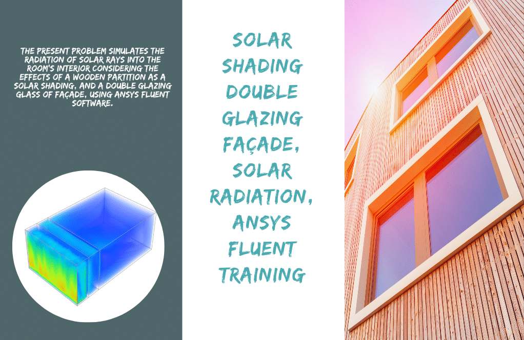
The Facade CFD simulates the airflow through the space between the two walls of the double façade of the building by ANSYS Fluent software applying a steady state, and Pressure-based solver, considering the gravity effect.
The geometry of the Facade CFD is three-dimensional and is drawn using Design Modeler software. The geometry consists of a rectangular cube chamber and several rows of shutter-like plates called shading.
The compartment has dimensions of 3 meters, 1.5 meters, and 0.2 meters. Shading plates also have a thin thickness with a slope of 45 degrees and are located in 120 rows. The meshing of the present model has been done using ANSYS Meshing software. The mesh type is unstructured and the element number is 4264442.
It is also assumed that the ambient airflow around the shells has a temperature of 300 K and a heat transfer coefficient of 10 W.m-2.K-1. Also, in the space between these two walls, a shutter-shaped shading is used, which helps the ventilation process in the system.
The purpose of this study is to investigate the behavior of fluid flow in an upward motion and heat transfer in space between two shells and between shading plates.
Methodology
The Energy equation is On to capture the temperature, and the Viscous is set as the Standard k-epsilon model.
To move the airflow upwards in this space based on the density changes caused by the pressure and temperature changes, the boundary condition of the pressure equal to the atmospheric pressure at the inlet and outlet of this space has been used.
The main cause of temperature changes is the presence of solar energy on the plates of these shells; therefore, the radiation energy model of Discrete Ordinates (DO) and the solar ray tracing model have been used.
Facade Results
At the end of the Facade CFD solution process, two-dimensional and three-dimensional contours related to pressure and velocity, and temperature, as well as two-dimensional and three-dimensional pathlines were obtained. The two-dimensional contours are drawn in the XY section and in the middle of the space between the two shells.
The diagram of the velocity distribution in the XZ section of the model is plotted at a height of 2 m from the floor of the model in the line passing through the center of the geometry and in line with the x-axis between -0.1 and +0.1. The geometric model has an angle of 45 degrees.
, Ansys Fluent Cfd Simulation Tutorial 9")
You can obtain Geometry & Mesh file, and a comprehensive Training Movie that presents how to solve the problem and extract all desired results.
1 review for Facade CFD Simulation Considering Radiation (HVAC), ANSYS Fluent CFD Simulation Tutorial
You must be logged in to post a review.
Related products
-
Sale

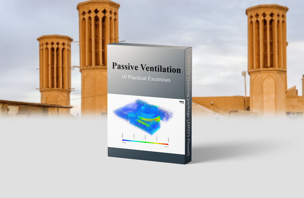
Passive Ventilation CFD Simulation Training Package, 10 Projects by ANSYS Fluent
Original price was: $980.00.$299.00Current price is: $299.00. Internship
Jordyn Kunde –
Can you explain more about the phenomena you’re simulating in the Facade HVAC CFD Simulation?
MR CFD Support –
Certainly! This simulation models the airflow and temperature distribution in a building with facade HVAC. It allows us to study and optimize the HVAC system’s performance and the building’s energy efficiency.
Madeline Kozakowski –
Clear walkthrough and helpful starting mesh. This has helped me decide to use another, more expensive guide.
Lorena Heller –
The facade CFD tutorial was insightful. I was particularly impressed with how the solar ray tracing model contributed to understanding the temperature changes on the shading plates. Great job!
MR CFD Support –
Thank you for your positive feedback! We’re glad to hear that our tutorial on facade CFD simulation was helpful and that you found the solar ray tracing model aspect insightful. Your understanding of temperature variations is crucial for optimizing HVAC designs. We appreciate your compliment and are here to provide further assistance if needed.
Nelda VonRueden –
I’m really impressed with how comprehensive this CFD project seems. Investigating the airflow and heat transfer in a facade system is no small task, and utilizing solar ray tracing is a crucial feature for real-world applications. Looking forward to seeing how simulations like this one can optimize building design for energy efficiency.
MR CFD Support –
Thank you for your positive feedback! We’re glad to hear that our Facade CFD simulation project met your expectations. Our goal is to provide detailed and accurate simulations that can truly aid in optimizing building designs for better energy efficiency. Your insights on the application’s real-world value align perfectly with our objectives. We appreciate your interest and support!
Eldridge Lehner PhD –
I found the use of shading plates in between the facade walls particularly innovative. Their inclination at 45 degrees and involvement in improving ventilation is a clever design choice. This CFD simulation serves as an excellent example of practical application in HVAC systems to enhance energy efficiency.
MR CFD Support –
We are thrilled to hear that our product has met your expectations and provided valuable insights into the design and efficiency of HVAC systems. Thank you for your positive feedback, and we are proud to have contributed to your understanding of fluid dynamics in building design. If you require more information or have further questions about our simulations, feel free to reach out.
Kip Kassulke –
I’m really impressed with the level of detail and precision this simulation has. It captures the intricacies of fluid flow within a complex structure like a double facade with utmost care. The inclusion of solar ray tracing to model the radiation effect is also remarkable.
MR CFD Support –
Thank you for the positive review! We’re glad to hear that the detail and precision of the simulation met your expectations, and that you found the inclusion of solar ray tracing to model radiation effects to be a significant feature. We strive to provide comprehensive and realistic CFD simulations. Your feedback is appreciated!
Benedict Von –
The tutorial on facade CFD simulation was truly informative. I now have a much better grasp on how to set up the double facade with proper solar radiation considerations for my HVAC studies. The inclusion of shading in the model was particularly clever. After going through the materials, I feel confident in setting up my own simulations. A top-notch learning tool for sure!
MR CFD Support –
Thank you for your kind words! We’re thrilled to hear that our Facade CFD Simulation tutorial has been helpful for your studies and that you now feel more confident in setting up your own simulations. It’s always satisfying to know that our customers can utilize our learning products effectively. We appreciate your feedback and are here to support you in your ongoing learning journey. Thank you for choosing MR CFD!
Cristal Hansen Sr. –
The tutorial sounds very detailed! It’s impressive that it includes solar radiation effects and airflow simulations. A great learning tool for understanding the complex interactions in façade designs.
MR CFD Support –
Thank you for your kind words! We’re delighted to hear that you find the tutorial on façade CFD simulation considering radiation effects valuable. It’s our aim to deliver comprehensive and practical learning content to help users understand and apply advanced simulations within ANSYS Fluent. Your feedback is very much appreciated!
Pearlie Hagenes –
The Facade HVAC CFD Simulation on your website is incredibly detailed. Excellent job!
Ms. Maud Stoltenberg –
I’ve been fascinated with how CFD can predict complex interactions in structures and was blown away by the quality of the facade CFD simulation package! The details about DO and solar ray tracing really explain the temperature distribution well. Awesome job showing the fluid behaviour and heat transfer!
MR CFD Support –
Thank you for your kind words! We’re delighted to hear that our facade CFD simulation tutorial met your expectations and helped clarify the thermal interactions and fluid behaviour in double façade structures. Your feedback is greatly appreciated, and we’re thrilled to have been a part of your learning journey. If you have any more questions or need further assistance, feel free to reach out!
Mr. Ward Hodkiewicz DVM –
I am thoroughly impressed with the detail and clarity offered in the Façade CFD simulation tutorial. It addresses key aspects essential in HVAC systems design, blending theoretical principles with practical application seamlessly. The tutorial not only provided substantial insights but also dealt with a real-world problem which is incredibly beneficial for learning. The inclusion of radiation considerations and solar tracing adds great value. Hats off to the team for this meticulous work!
MR CFD Support –
Thank you so much for your kind words and the positive feedback! We’re delighted to hear that our tutorial on Façade CFD simulation has been instrumental in enhancing your understanding of HVAC systems design. Our team strives to ensure that our simulations are as informative and applicable to real-world scenarios as possible. We are pleased that the intricacies incorporated, especially concerning radiation and solar energy modeling, resonated well with you. Your appreciation is a great encouragement for us to continue delivering high-quality training material. Thank you again for choosing our products for your learning journey!
Dr. Bonnie Parisian –
Great tutorial! Everything was explained so clearly that I had no trouble running the simulation and understanding how the airflow and temperature distribution can be influenced by proper shading and ventilation design.
MR CFD Support –
Thank you for your positive feedback! We’re thrilled to hear our tutorial has been helpful for you to understand the complex interaction between airflow, temperature, and shading in building design. We strive to provide clear and comprehensible CFD training and are glad you found everything to be clear and straightforward. If you have any further questions or need assistance with more simulations, please feel free to reach out to us.
Nikki Beahan –
The use of shading plates in this simulation seems quite innovative. One can see its utility in the presentation of the velocity and temperature contours. Well done on the detailed work!
MR CFD Support –
Thank you for your compliment! We’re glad to hear that you recognize the innovation in our simulation approach. If you have any further questions or need assistance understanding our simulation process, please don’t hesitate to ask.
Miss Kaylin Macejkovic II –
This tutorial was exactly what I needed for understanding thermal behavior in double-skin facades. The step-by-step approach complemented my studies as an architectural engineer, and I appreciate the comprehensive training material included.
MR CFD Support –
Thank you so much for your kind words. We’re thrilled to hear our tutorial on facade CFD simulation was helpful for your studies. Your feedback is greatly appreciated, and if you need further assistance or more resources, feel free to reach out to us!
Ervin Weimann –
I’m impressed by the level of detail in the Facade CFD Simulation tutorial. It was a great learning experience to see how the Discrete Ordinates (DO) and solar ray tracing models were applied. The results provided a clear understanding of temperature distribution and airflow dynamics across the facade.
MR CFD Support –
Thank you for your positive feedback! We’re thrilled to hear that the tutorial was informative and met your expectations. It’s always great to know when our customers find the learning material valuable and the outcomes of the simulation clear. If you have any further questions or need more insights into our simulation approaches, feel free to reach out.