Wind Tower with Qanat, ANSYS Fluent CFD Simulation Training
$80.00 Student Discount
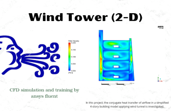
- The present CFD Project simulates a Wind Tower with Qanat via ANSYS Fluent software.
- We modeled the geometry using ANSYS Design modeler software and created the mesh using ANSYS meshing software.
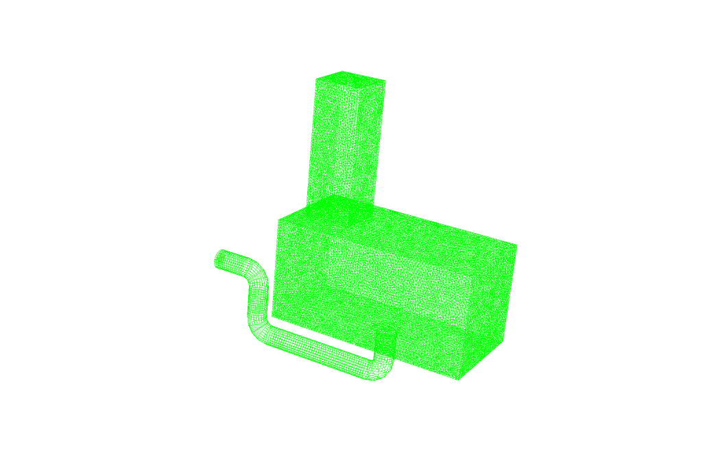
- The total number of elements is 402,198.
- Incompressible Ideal Gas has been used to define density changes.
To Order Your Project or benefit from a CFD consultation, contact our experts via email ([email protected]), online support tab, or WhatsApp at +44 7443 197273.
There are some Free Products to check our service quality.
If you want the training video in another language instead of English, ask it via [email protected] after you buy the product.
Description
Introduction
This project is related to a simulation of a wind tower system with qanat using ANSYS Fluent software. We perform this CFD project and investigate it by CFD analysis.
This system is included in the category of passive ventilation methods. In passive ventilation systems, no mechanical device is involved.
Generally, passive ventilation systems are included in two groups, which are wind-driven and buoyancy-driven. In the wind-driven method, the pressure difference is the factor of air circulation, and in the buoyancy-driven method, the density difference leads to natural convection heat transfer.
The wind tower ventilation system with qanat is placed in the hybrid passive ventilation group (a combination of two groups).
The wind tower system with qanat is one of the traditional ventilation systems based on the architecture of old buildings. This system was very popular in dry and hot areas.
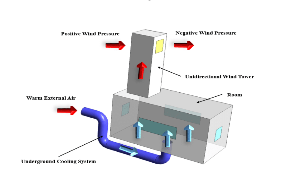
In this system, a tall wind tower is placed on top of the building, and an underground cooling system is considered. In this project, we are using qanat as an example of a common underground cooling system.
When a large structure faces the wind flow, a significant pressure difference appears on its two sides. In front of the structure is a high pressure, and behind it is a pressure vacuum, which leads to air suction caused by the pressure difference.
On the other hand, inside the cooling system or qanat channel, cold water is up to a certain level. The free wind flow enters the channel, and after hitting the water surface, it cools and moistens. This cool air enters the interior of the building from the floor and performs the air conditioning process.
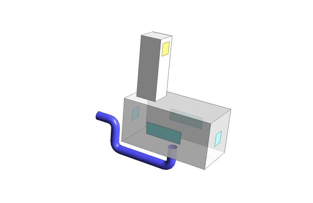
In this problem, the free hot air flow enters the cooling channel with a velocity of 0.2 m/s and a temperature of 300 K. To simplify the problem; we avoided modeling the water level inside the channel and used the constant temperature boundary condition. We assumed that the wall of the underground channel has a constant temperature of 278 K.
We have also modeled some windows on the walls of the room. These windows are exposed to sunlight and in contact with the hot air of the outside environment. So we have assumed that the glass windows have a constant temperature of 298K.
We designed the geometry of the model using Design Modeler software. The current model includes three parts: room, tower and underground channel.
Then we meshed the model using ANSYS Meshing software. The meshing is unstructured, and the number of created cells equals 402198.
Wind Tower Methodology
Using ANSYS Fluent software, we numerically simulated this model according to computational fluid dynamics (CFD). This problem is independent of time and steady state, and the solution is based on the pressure-based solver.
As we said, natural convection heat transfer also happens in this problem. Natural convection is created based on the buoyancy effect. This means that changes in temperature cause changes in density. Warm air is lighter and less dense and rises upwards.
Therefore, the current system is useful for the exit of hot air. The entry of cool air from the floor of the room and the air suction from the exit panel of the tower helps the exit of hot air.
We do not consider the air density constant to apply the buoyancy effect. The relation between density, pressure, and temperature according to the ideal gas law is used in the incompressible ideal gas model. Note that the density is dependent on the operating pressure and is independent of the local relative pressure. So assuming constant pressure, density becomes a function of temperature.
Wind Tower Conclusion
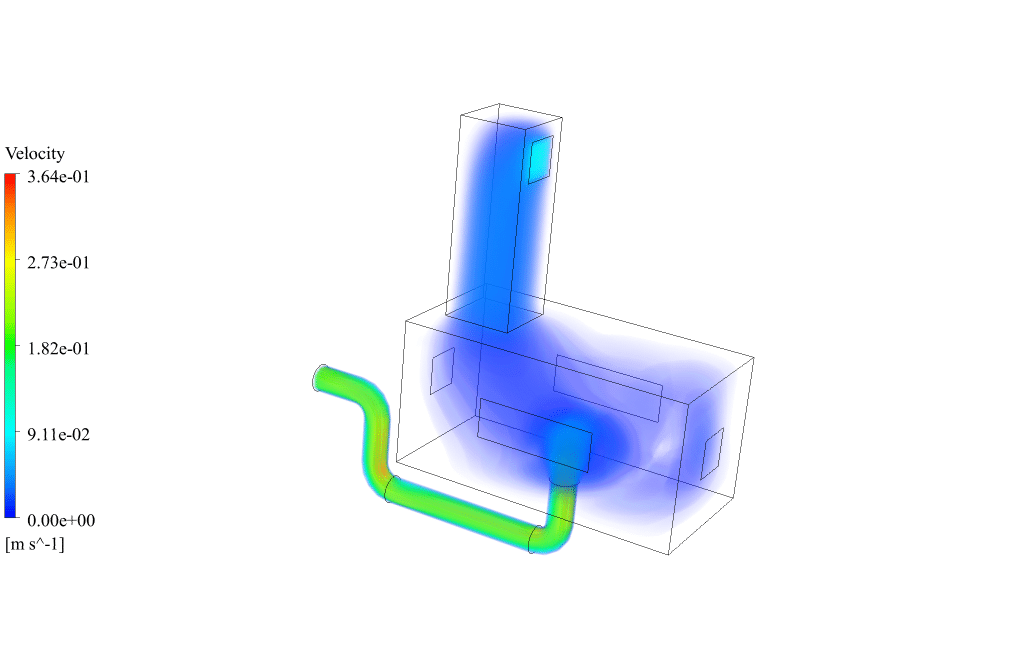
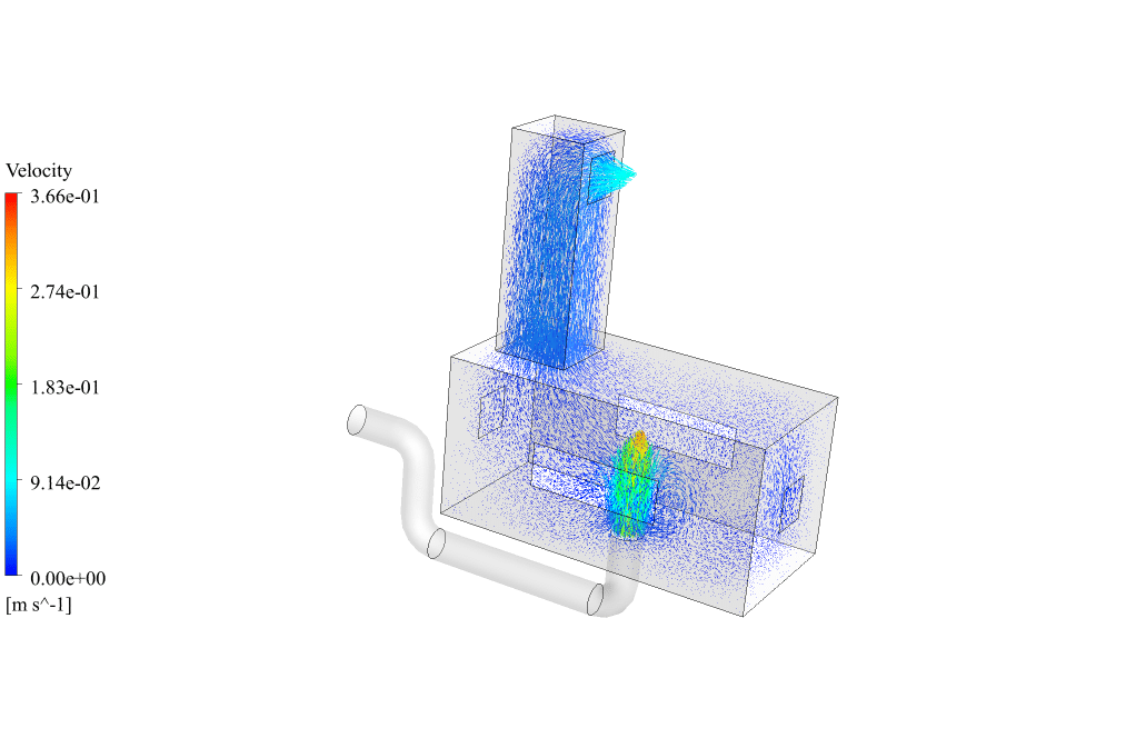
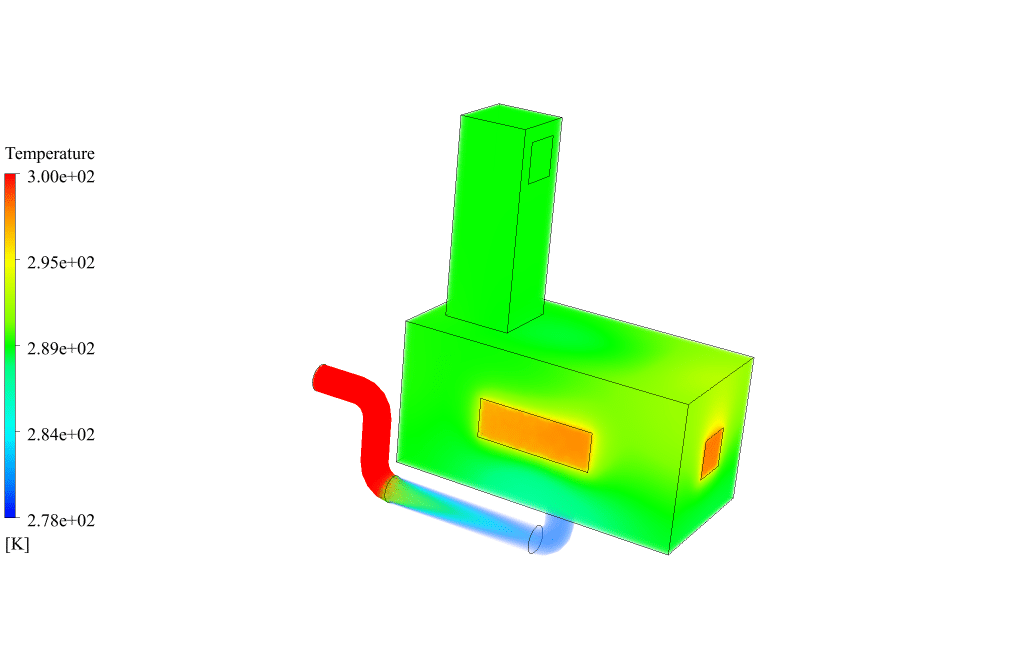
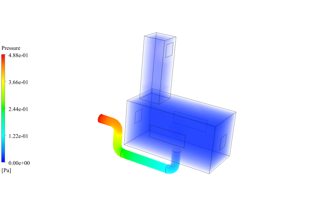
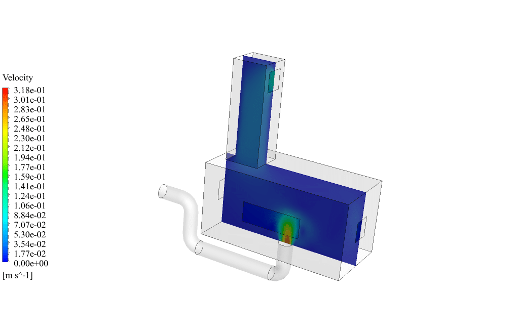
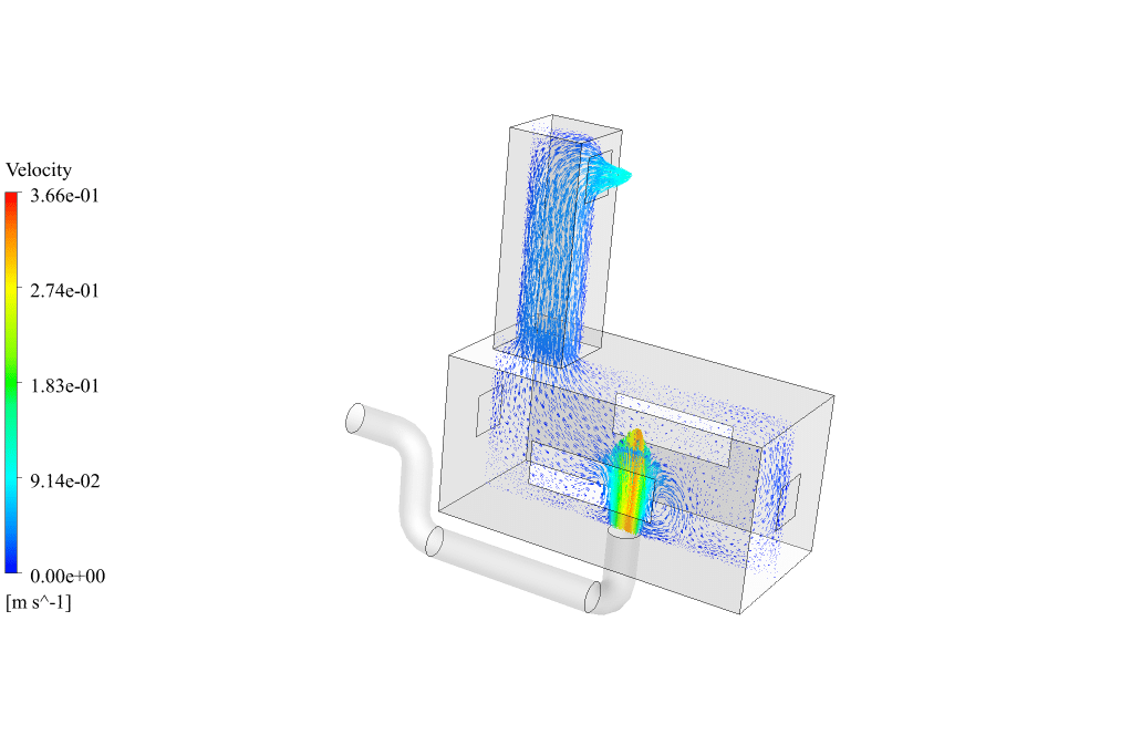
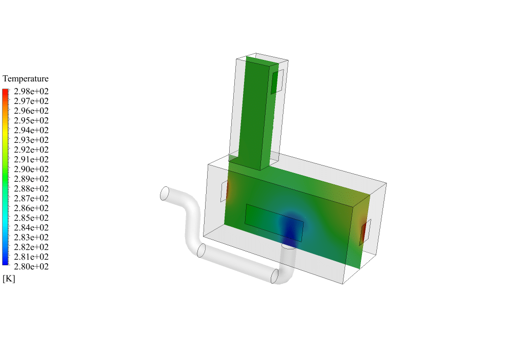
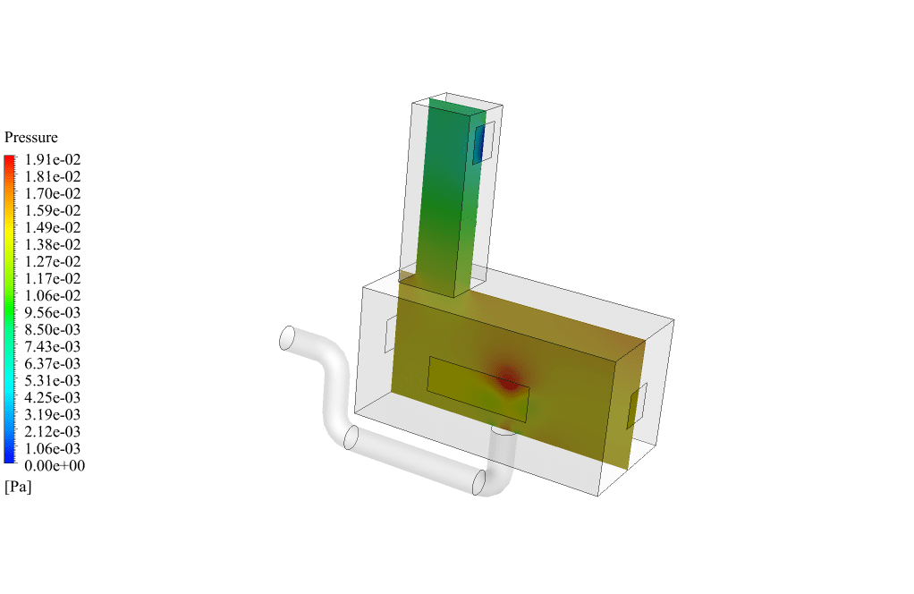
After the simulation, we obtained 2D and 3D temperature, pressure and velocity contours. We also obtained 2D and 3D velocity vectors.
The temperature contour shows well the cooling process inside the room. Cool air enters the underground channel, and hot air exits from the tower panel.
The pressure contour also shows the pressure difference well. The high pressure of the external air and the low pressure inside the room and tower cause hot air to be sucked out.
Velocity vectors show the direction of air movement inside the room and tower well. Cool air enters the room at high speed from the floor, and after full circulation in the room and air conditioning, it leaves through the tower.
So we conclude that we perform the simulation correctly. The passive ventilation system of the wind tower and qanat perform the air conditioning operation correctly.

Prof. Hope Block III –
I really appreciated the thermal management concept in the simulation. Could you explain more on how the cooling effect within the qanat enhances the overall system’s efficiency?
MR CFD Support –
Certainly! The qanat acts as an underground channel that provides a cool surface through its constant temperature walls. As the hot wind enters the tower and reaches the qanat, it interacts with this cooler surface and transfers heat to it, thereby reducing the air temperature due to the heat exchange process. As this cooler air then moves into the interior of the building, it helps in lowering the overall temperature. The efficiency of the system is tied to the temperature difference between the ambient hot air and the cooler surfaces of the qanat, and the capacity of the qanat to maintain this temperature gradient despite the continuous air supply. Essentially, the qanat’s ability to consistently present a cooler boundary to the incoming warmer air is what enhances the system’s efficiency in terms of passive cooling.
Urban Reichel –
Wonderful training course! The way the wind tower with qanat simulation integrates traditional methods with modern CFD analysis is fascinating. It was very insightful to see how passive ventilation systems work in detail.
MR CFD Support –
Thank you for your kind words! We’re delighted to hear that you found our simulation training on the wind tower with qanat insightful and that it helped you understand the functionality of passive ventilation systems. It’s great to see traditional systems coming to life through modern analysis. Your feedback is greatly appreciated!
Hallie Kemmer I –
I really appreciate the innovative approach of combining traditional architecture with modern simulation techniques to enhance passive cooling systems. The commitment to sustainability and the utilization of natural resources is certainly commendable.
MR CFD Support –
Thank you so much for your kind words. We’re thrilled to know that our approach to blending heritage with cutting-edge technology could earn your enthusiasm. It’s always our goal to provide valuable insights while promoting sustainability.
Ms. Melisa Fadel DDS –
I’m very impressed with how the old architectural concepts are integrated with modern simulation tools. The use of passive cooling in this CFD simulation is fascinating. Great job on providing details on how the wind tower with qanat works and explaining the effectiveness through simulation results.
MR CFD Support –
Thank you for your positive feedback! We’re glad you appreciated the integration of traditional architecture with contemporary simulation technology in the Wind Tower with Qanat project. It’s always rewarding to know that our efforts to provide detailed and comprehensive simulations are valued by our customers. If you have any more questions or need further information, please don’t hesitate to ask.
Raina Goyette Jr. –
The 3D models of temperature, pressure, and velocity were very insightful. They aptly demonstrated the effectiveness of traditional architecture in natural ventilation.
MR CFD Support –
Thank you for your positive feedback regarding the 3D contour models in our wind tower with qanat CFD simulation! We’re glad to hear that the results resonated with you and provided valuable insights into traditional passive ventilation systems. We appreciate your appreciation of the detailed analysis provided in the training.
Winifred Russel –
I greatly appreciated learning about the traditional wind tower and qanat systems through the ANSYS Fluent simulation dataset. It’s fascinating to observe how modern computational tools can model these intricate ancient solutions, effectively showing the temperature, pressure, and velocity changes within the environment. Simultaneously analyzing the steady-state physical phenomena and examining the contours as it illustrates a cool breeze meandering through the tower is simply impressive. The detailed CFD analysis contributes significantly to understanding building behavior in various climatic conditions.
MR CFD Support –
Thank you so much for your positive feedback! We’re really glad to hear that our simulation product on the wind tower with qanat in ANSYS Fluent has provided valuable insights for you. Understanding traditional systems with cutting-edge CFD tools is indeed exhilarating and offers in-depth knowledge not only historically but practically for modern applications. It’s rewarding to know that the product was informative and enjoyable for you.
Mr. Freeman Kihn –
What a refreshing insight into traditional architecture paired with modern technology! The methodic approach in analyzing the hybrid passive ventilation system showcases the potential of underutilized natural cooling. The marriage of a wind tower and qanat with CFD proved both practical and effective, an example of sustainable practices catching up with computational insight.
MR CFD Support –
Thank you so much for your positive review! We’re delighted to hear that the CFD simulation of the traditional wind tower with qanat met your standards and provided valuable insights. It’s always inspiring to know that our customers recognize the importance of integrating sustainable architectural practices with cutting-edge technology. If you have any more questions or need further assistance, please do not hesitate to let us know.
Annabell Abshire V –
I am impressed by the detailed passive cooling system you have presented in the wind tower and qanat simulation. The application of historical methods in modern architecture using simulation tools is very exciting. Well done on capturing such intricate environmental interactions!
MR CFD Support –
Thank you for your kind words! We’re thrilled to hear that you found the wind tower and qanat simulation interesting and that you appreciate the integration of historical cooling methods with modern simulations. It’s always encouraging to know that our efforts to blend traditional wisdom with contemporary technology are well-received. If you have any further inquiries or need assistance with similar projects, please don’t hesitate to contact us!
Queen Blanda –
The inclusion of the wind tower with qanat in the passive ventilation systems is pretty intriguing! Great job on how detailed the simulation dynamics are displayed.
MR CFD Support –
Thank you for your positive feedback! We’re glad to hear that the details of the wind tower with qanat simulation were helpful and informative. Our aim is to provide accurate and comprehensive simulations to enhance understanding of passive ventilation systems.
Myrtie Lebsack –
The simulation of a wind tower with qanat in ANSYS Fluent seems fascinating! How effective is this traditional system compared with modern air conditioning in terms of energy efficiency?
MR CFD Support –
Thank you for your interest in the wind tower with qanat simulation. Traditional systems like the wind tower with qanat are indeed fascinating. In terms of energy efficiency, these systems are highly effective as they use natural forces like wind and thermal buoyancy instead of electrical energy to function. They are passive systems, so their operation cost is significantly lower than that of mechanical air conditioning systems. While they may not always match the cooling capacity of modern air conditioners, they are environmentally friendly and sustainably manage the interior climate, particularly in the regions for which they were designed.
Miss Bailee Murazik Sr. –
I just completed the Wind Tower with Qanat ANSYS Fluent CFD Simulation and the training was impressive! The integration of traditional architecture with modern simulation tools provided me with a unique understanding of passive ventilation systems. I really appreciated how the concept of buoyancy-driven convection was demonstrated and the use of constant temperature boundaries to simplify the underground cooling channel conditions made the concept crystal clear.
MR CFD Support –
We are delighted to hear that you had an impressive learning experience with our Wind Tower with Qanat ANSYS Fluent Simulation training! It’s wonderful to know that the training effectively conveyed the principles of passive ventilation and buoyancy-driven convection. Thank you for appreciating the integration of traditional systems and simulation technologies, and we’re glad that the simplifications helped in your understanding. Your feedback is greatly valued, and we look forward to continuing to support your learning journey.
Kamron Maggio –
This training has been crucial in enhancing my understanding of natural ventilation systems, especially hybrid ones incorporating both wind-driven and buoyancy-driven techniques. The clarity of the explanations regarding temperature contours and velocity vectors in the results facilitated a solid grasp of how air movement and temperature distribution occurs within these systems. A job well done on this comprehensive CFD training package.
MR CFD Support –
Thank you for your positive feedback! We’re thrilled to hear that our training on wind tower and qanat systems in ANSYS Fluent has enriched your knowledge and provided clear insights into natural ventilation systems. Your understanding of the subject matter is a testament to the quality of our educational materials. Should you have any further questions or require more in-depth training, please feel free to reach out to us.
Durward Kunde DDS –
Just wanted to say that the simulation project’s detail and comprehensive analysis is top-notch. The integration of the qanat for cooling is an innovative approach to sustainable architecture, and the 3D temperature visualizations really helped me grasp the effectiveness of this system. Fabulous work, MR CFD!
MR CFD Support –
Thank you very much for your kind words! We’re glad to hear that our detailed analysis and visualizations were helpful to you. It’s fantastic to know that the traditional and sustainable techniques like the wind tower with qanat simulation are of interest and value to our customers. If you have any more thoughts or need further assistance, feel free to reach out. We look forward to providing you with more CFD insights in the future!
Cassandre Gerhold –
I’ve always been fascinated by historical architecture, and the simulation of a wind tower with qanat in ANSYS Fluent sounds impressive! This traditional method, combining natural elements to create a comfortable environment, is innovative yet grounded in heritage. Kudos to MR CFD for harnessing this ancient wisdom and presenting it through modern simulation techniques!
MR CFD Support –
We’re delighted to hear that our simulation of the wind tower with qanat has fascinated you, and you appreciate the connection between traditional methods and modern technology! Thank you for recognizing our efforts to integrate historical architecture with contemporary CFD analysis. Your support inspires us to keep exploring and educating about sustainable practices in innovative ways.
Miss Therese Medhurst –
I’m fascinated by the wind tower and qanat system described. Could you elaborate on how the constants for the temperature of the underground channel walls and the glass windows were determined?
MR CFD Support –
In this simulation, the temperature constants are typically chosen based on average expected conditions or specific design requirements. The constant temperature of the wall of the channel at 278 K represents a typical temperature of soil or underground environments in certain geographical locations. The glass windows having a constant temperature of 298 K could be based on the average temperature observed due to solar heat gain in that local climate. In order to set the boundary conditions appropriately, these constants are chosen in such a way that they best represent the physical system being modeled.
Mallory Kessler –
The description very thoroughly explains how the system functions. The addition of temperature assigned to the glass windows sounds like an intricate detail strengthening the simulation realism. The consideration of buoyancy effects in the simulation appears to also create a more accurate model of natural convection.
MR CFD Support –
Thank you for recognizing the level of detail in our simulation with the Wind Tower and Qanat system. We strive to create the most realistic conditions in our models, including those small but critical aspects like the temperature of the windows which significantly affect the outcome. Your appreciation for the inclusion of buoyancy effects and acknowledgment of their importance in natural convection models confirms our commitment to providing high-quality, comprehensive simulations.
Maria Thiel –
The detailed explanation of the qanat system assimilation of cool air and release through the wind tower is illuminating. It’s fascinating to visualize the transfer from historical architecture into the realm of modern computational analysis. The temperature and pressure contours and 3D modeling really seem to bring this ancient technology to life!
MR CFD Support –
We’re thrilled to hear your positive feedback about our Wind Tower with Qanat CFD simulation training. It’s rewarding to see our efforts to bridge ancient techniques with cutting-edge computational methods resonate with our users. Thank you for taking the time to share your review, and we’re glad you found the visualization helpful.
Dr. Raina Strosin III –
The training and simulation work presented in this review look meticulously prepared and detailed. The incorporation of ancient techniques combined with modern simulation seems particularly intriguing, as it demonstrates a rich blend of historical learning with advanced technology. Overall, these results suggest a valuable educational experience.
MR CFD Support –
Thank you for your positive feedback on our ANSYS Fluent CFD Simulation Training for the Wind Tower with Qanat project. We strive to bring together the best of traditional knowledge and contemporary simulation techniques for an enriching learning experience. We’re pleased to hear that the training made an impact and appreciate your comments.
Alanna Welch –
I’m fascinated by the traditional wisdom behind these structures! Can you share any insights on how well the simulation aligned with the historical data on wind towers and qanats efficiency?
MR CFD Support –
In the MR CFD simulations, we strive to closely replicate historical designs and their operational efficiencies as much as possible. While the simulations are informed by the fundamental principles of the original systems, evaluating how closely the simulation aligns with historical data would typically require direct comparison with empirical data from real-world wind towers and qanats. Since this detail isn’t provided, such a comparison isn’t specified. However, the simulation’s results should provide good insights into the operational efficacy of the modeled structures from a theoretical perspective.
Heidi Pollich –
The results of the simulation sound effective. Was the humidity frontier monitored, given that the air flow first hits the water surface in the system?
MR CFD Support –
In this simulation, the humidity condition is not explicitly monitored as the project simplifies the problem by avoiding the modeling of water levels in the channel. Instead, it assumes a constant temperature of the underground channel’s wall to represent the cooling effect of the qanat. Therefore, the air’s moisture increase after contact with water isn’t part of the analysis.
Ebba Legros –
I’m impressed by how this ancient architecture has been modeled for modern analysis. Is the assumption of the windows having a constant temperature of 298K made for simplicity, and can this be adjusted through parameter studies for more accurate real environmental interaction effects?
MR CFD Support –
Thank you for your interest in our simulation training. Yes, the constant temperature assumption for the window was done to simplify the analysis for a steady-state condition. However, we certainly can adjust and perform parameter studies to take into account the varying environmental conditions and achieve even more accurate representations of real world effects. We can simulate different external temperature scenarios to see how this affects the system performance.