Fuel Injection inside a Chamber 2-D CFD Simulation
$100.00 Student Discount
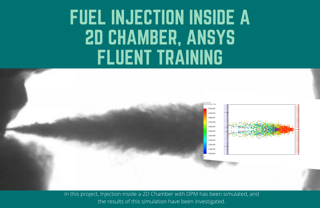
In this project, Injection inside a 2D Chamber with DPM has been simulated, and the results of this simulation have been investigated.
Click on Add To Cart and obtain the Geometry file, Mesh file, and a Comprehensive ANSYS Fluent Training Video.To Order Your Project or benefit from a CFD consultation, contact our experts via email ([email protected]), online support tab, or WhatsApp at +44 7443 197273.
There are some Free Products to check our service quality.
If you want the training video in another language instead of English, ask it via [email protected] after you buy the product.
Description
Fuel Injection inside a Chamber 2-D CFD Simulation, ANSYS Fluent Training
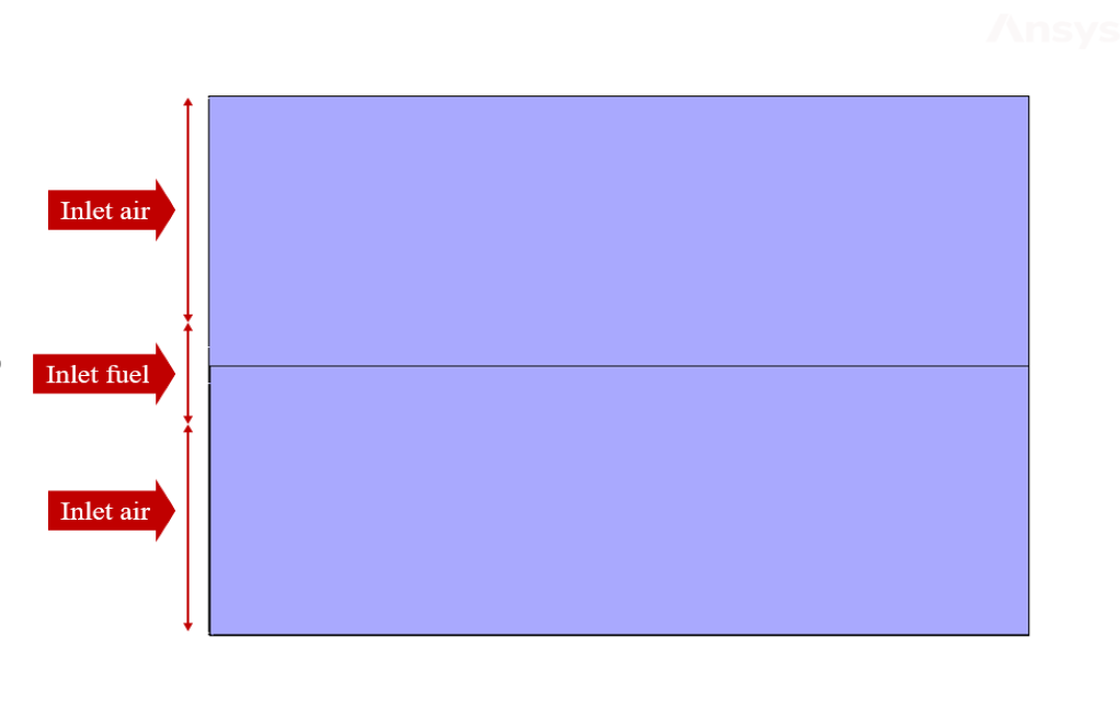
The simulation is about fuel injection in a 2D chamber via ANSYS Fluent. In this project, a two-dimensional cylindrical chamber is designed. Fuel flow from the center and airflow from the outside into the chamber.
A Discrete Phase Model must be used to define fuel injection, and an injection process must be defined from the central part of the chamber. The airflow inside the chamber is continuous, and the fuel flow enters the chamber discretely.
Thus, the solution perspective changes from Eulerian to Lagrangian by creating an interaction between discrete particles and a continuous medium. The fuel material is injected surface type in the form of inert particles and has a velocity of 1 m.s-1 and a diameter of 0.0002 m, injected in 0 s to 1 s.
To define the boundary conditions, the velocity boundary condition for airflow is used; So that air enters the chamber at a speed of 0.2 m.s-1. The modeling is unsteadily (Transient), and the time step is equivalent to 0.002 s.
Geometry & Mesh
The present geometry is designed in a 2D model via Design Modeler. The computational zone is the interior of a chamber that includes an airflow inlet and a fuel inlet.
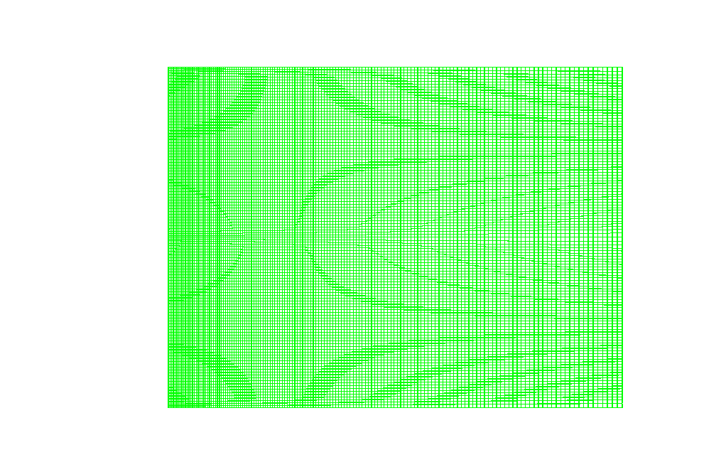
The mesh of the present model has been done via ANSYS Meshing. Mesh is structured, and the number of production cells equals 9211.
Set-up & Solution
Assumptions used in this simulation :
- Pressure-based solver is used.
- The present simulation is unsteady.
- The effect of gravity with a gravitational acceleration of 9.81 m.s-2 has been applied to the model.
| Models | ||
| Viscous | k-omega | |
| k-omega model | standard | |
| Discrete Phase Model | On | |
| number of injections | 1 | |
| injection type | surface | |
| particle type | inert | |
| Boundary conditions | ||
| Inlet (air) | Velocity Inlet | |
| velocity magnitude | 0.2 m.s-1 | |
| discrete phase BC type | escape | |
| Inlet (fuel) | Velocity Inlet | |
| velocity magnitude | 1 m.s-1 | |
| discrete phase BC type | escape | |
| Walls | Wall | |
| wall motion | stationary wall | |
| discrete phase BC type | reflect | |
| Outlet | Pressure Outlet | |
| gauge pressure | 0 pascal | |
| discrete phase BC type | escape | |
| Methods | ||
| Pressure-Velocity Coupling | Coupled | |
| pressure | PRESTO | |
| momentum | second-order upwind | |
| species fraction | second-order upwind | |
| turbulent kinetic energy | first-order upwind | |
| specific dissipation rate | first-order upwind | |
| Initialization | ||
| Initialization methods | standard | |
| gauge pressure | 0 pascal | |
| x-velocity | 0.2 m.s-1 | |
| y-velocity | 0 m.s-1 | |
Fuel Injection inside a 2D Chamber Results
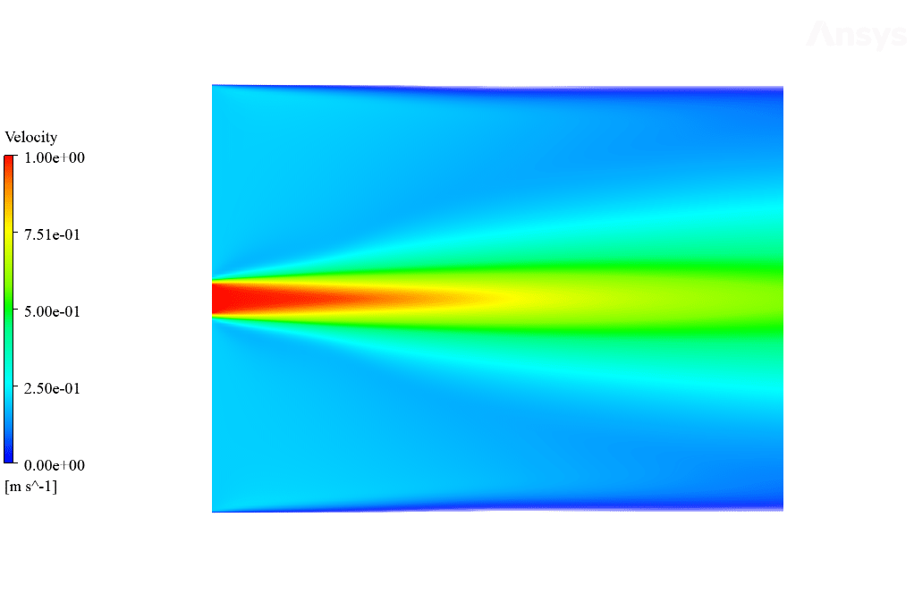
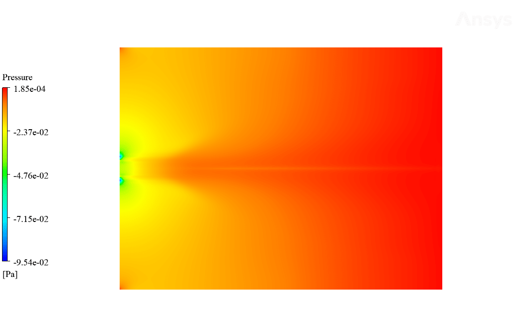
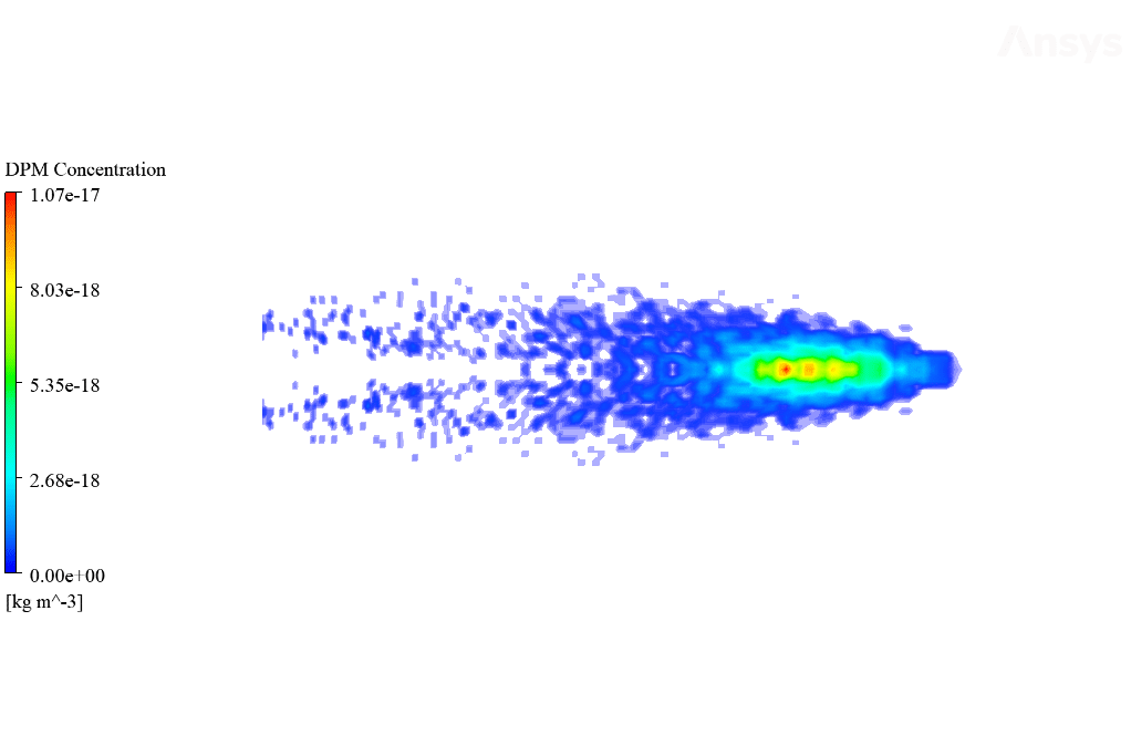
After calculation, 2D contours related to velocity and pressure, and DPM concentration are obtained. The contours show that The velocity and pressure in the fuel inlet section are higher than in other zones because it is injected into the space inside the chamber at a higher speed.
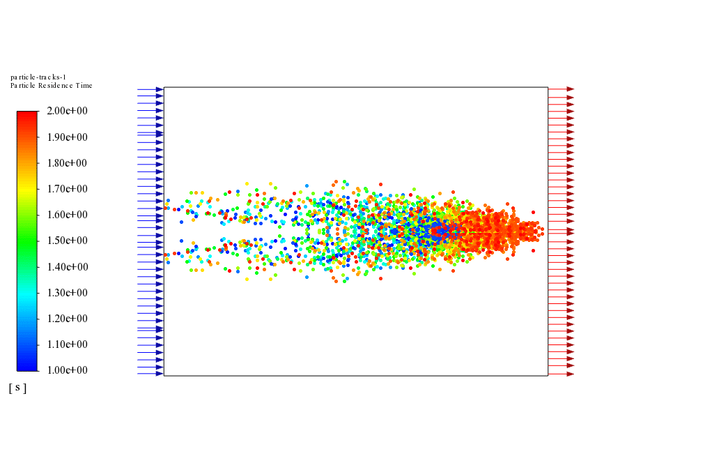
Also, a particle track related to the discrete phase model has been obtained in the chamber’s interior, which shows how the discrete phase is dispersed and its impact from the continuous airflow.
The simulation is performed in 2 s, and the discrete phase propagation process occurs in its initial 1 s. Thus, the discrete phase concentration contour and the discrete particle sequence show that the desired discrete particles are directed to the output port of the chamber over time.

Linda Maggio DVM –
This session was immersive and insightful! The level of detail in demonstrating how both discrete and continuous phases interact within the chamber provided a clear understanding of fuel injection dynamics. Appreciate the comprehensive simulation setup explanations.
MR CFD Support –
Thank you for your positive feedback! We’re thrilled to hear that you found our simulation on fuel injection in a 2-D chamber both immersive and informative. Our goal is always to provide detailed and clear insights into complex fluid dynamics, and we’re glad we met your expectations.
Rebecca Schamberger –
I am truly impressed with the detail of the fuel injection CFD simulation and the clarity of the explanation provided in the product description. The results appear to exactly demonstrate the complexity and behavior of multiphase flows in engineering applications. Great work by MR CFD on this intricate topic!
MR CFD Support –
Thank you very much for your kind feedback! We’re delighted to hear that the Fuel Injection inside a Chamber 2-D CFD Simulation met your expectations. It’s our aim to deliver comprehensive and clear educational materials that help our customers understand complex topics with ease. We appreciate your recognition of our efforts!
Elroy Olson –
The use of a Pressure-Based solver and a Coupled Pressure-Velocity coupling in the fuel injection simulation seems very interesting. Can you explain the reason behind choosing these specific methods for this scenario?
MR CFD Support –
The Pressure-Based solver is suitable for incompressible and mildly compressible flows, frequently encountered in fuel injection simulations. Using a Coupled Pressure-Velocity coupling method is preferred for steady flows as it solves the momentum and pressure equations simultaneously, allowing for faster convergence and more accurate results in reactions like fuel dispersion within the chamber. These methods provide a balanced approach for dealing with the fluid interactions and the continuous-discrete phase coupling inherent in fuel injection scenarios.
Mr. Josh Runolfsdottir Sr. –
I’m truly impressed by the detailed results obtained from the Fuel Injection inside a Chamber 2-D CFD Simulation by MR CFD Company, especially the representation of discrete phase dispersion and its interactions. The clarity on velocity and pressure variations throughout the chamber are particularly useful for analysis. Great work!
MR CFD Support –
Thank you for your positive feedback on our Fuel Injection CFD simulation training! We are thrilled to hear that you found the detailed results and the representations of the discrete phase to be clear and informative. Your satisfaction with the analysis and the learning outcome is very important to us. If you have any further questions or need more insights, feel free to reach out!
Jarred Romaguera –
The explanation of the simulation setup is so comprehensive! Looking forward to applying this knowledge to my project. Great work!
MR CFD Support –
Thank you for your kind words! We’re thrilled to hear you found the simulation setup explanatory and useful. If you have any upcoming projects or need further insights, feel free to reach out. Good luck with your project!
Mr. Danny Bartoletti PhD –
The detailed simulation steps helped me grasp the entire process well. I appreciate the inclusion of pressure and velocity contours and the clear explanation of the particle track results. Kudos on delivering a comprehensive training tool.
MR CFD Support –
We’re thrilled to hear you found the training material comprehensive and useful! It’s great to know that our efforts in providing clear explanations and detailed simulation steps are appreciated. Thank you for taking the time to leave a positive review.
Duncan Lemke –
The training and provided output demonstrate an in-depth simulation process, complemented by comprehensive modeling and thoughtful setup. Superb work on showing the discrete phase propagation seamlessly interacting with the continuous airflow. The visuals for tracking the particles add crucial understanding to the simulation’s effectiveness!
MR CFD Support –
Thank you for your enthusiastic review! We are glad that the detailed simulations and the visualization of the discrete phase interactions provided you with an insightful understanding of the process within the chamber. Your feedback is appreciated and motivates us to continue delivering high-quality training materials.
Alice Franecki –
I found the detailed description of the boundary conditions very helpful in understanding the setup. However, could you explain if the REFLECT boundary condition on the walls affects the distribution of the fuel particles significantly?
MR CFD Support –
Yes, the REFLECT boundary condition on the walls can significantly affect the distribution of the fuel particles. This condition causes the particles to bounce back off the walls, which can impact the overall flow and distribution of the fuel particles within the chamber. The specific effects would depend on various factors such as the velocity of the particles, the angle of incidence at which they hit the wall, and the properties of the wall material in terms of reflectivity.
Danika Bode –
I’m truly fascinated by the approach taken for the interaction of discrete particles with a continuous medium. However, could you please clarify for me if the boundaries for fuel injection and air inflow have different conditions or do they operate under the same principles?
MR CFD Support –
Yes, the fuel injection and air inflow have distinctly differentiated boundary conditions according to their specific roles in the simulation. For the fuel injection, we deploy a ‘Velocity Inlet’ with a velocity magnitude of 1 m/s for the discreetly entering fuel particles. Conversely, for the air inflow, a slower ‘Velocity Inlet’ is applied, with a velocity magnitude of 0.2 m/s, to represent the continuous flow of air into the chamber. The discrete phase boundary conditions reflect this difference, ensuring fuel particles efficiently interact with the air within the simulation environment.
Antonina Daniel –
The explanation of the results from the fuel injection simulation was very informative! It’s fascinating to understand how the discrete particles are influenced by the airflow.
MR CFD Support –
Thank you for your positive feedback! We’re glad to hear the result explanations provided clarity on the intricate interactions within the simulation. Your appreciation truly motivates us to continue delivering detailed and informative content!
Darrel Gottlieb –
The training was excellent. It did a great job of elucidating fuel injection processes, and I could visualize the concepts thanks to the DPM concentration contours. Well-structured mesh and simulation steps made complex theories much easier to grasp!
MR CFD Support –
We’re truly grateful for your positive review. It’s fantastic to hear that the DPM concentration contour visuals were helpful and that the step-by-step guidance made the content accessible. Your comprehension of the fuel injection process is precisely what we aim to achieve. Thank you for choosing our training product!
Olen Walsh Sr. –
This simulation seems incredibly detailed. Could you explain how turbulence is managed within this 2-D chamber scenario?
MR CFD Support –
The turbulence within the 2-D chamber is managed using the k-omega turbulence model. This statistical model handles turbulence by solving two transport equations, one for the turbulence kinetic energy (k) and the other for the specific dissipation rate (omega, ω), to provide a detailed description of the turbulent flow. The interaction of the continuous airflow with the injected fuel particles and any resulting turbulent eddies are accounted for by this model, enabling a realistic simulation of the dispersion of the fuel within the chamber.
Mrs. Minnie Jerde IV –
The tutorial seems comprehensive, but could you explain if the fuel particle sequence is visualized at different time steps, and how can one interpret these visual results?
MR CFD Support –
In the tutorial, the fuel particle track reflecting the Discrete Phase Model is indeed visualized at different time steps, showing the path these discrete particles take as they are influenced by the continuous airflow inside the chamber. To interpret these visual results, you’d analyze how the particles distribute and propagate over time, observing their path-lines and their interactions, such as collisions with the chamber wall or their escape through the outlet, providing insights into the injection efficiency and mixing processes.
Miss Ernestine Daugherty –
I’m amazed at how detailed the results are! Were any particular challenges addressed when modeling the interaction between the discrete particles and continuous phase?
MR CFD Support –
Thank you for your kind feedback! The main challenge in modeling the interaction between the discrete particles and the continuous phase lies in accurately capturing the momentum exchange between them. With computational models like the Discrete Phase Model employed in this simulation, we closely approximate physical behaviors such as drag, turbulence modulation, and heat transfer to reflect real-world reactions. Appropriate numerical techniques, such as proper discretization methods for momentum and precise time-stepping, are critical for capturing such interactions. We strive to refine our models continually to ensure realistic and robust simulation outcomes.
Terrell Reichel –
Great level of detail in your simulation! It demonstrated a sophisticated understanding of CFD principles, especially the use of DPM in a 2D chamber environment. The technical insights from velocity and pressure distributions to DPM concentration have given me deeper insights into fuel injection systems. Thanks for such an enlightening product!
MR CFD Support –
Thank you for your positive feedback! We’re delighted to hear that our Fuel Injection inside a Chamber 2-D CFD Simulation was able to enhance your understanding of CFD applications in fuel systems. If you have any more questions or need further information, please feel free to reach out.
Miss Elvie Luettgen –
I learned a lot about fuel injection CFD simulation with this exceptional training product. The details provided were nuanced, and I appreciate the rigorous setup explained for handling the discrete phase injection and interaction with continuous airflow.
MR CFD Support –
Thank you for your kind words! We are thrilled to hear that you found the Fuel Injection inside a Chamber 2-D CFD Simulation training insightful and helpful. Your success with understanding the complexities of fuel injection using CFD is our top priority. Please don’t hesitate to reach out if you have further questions or need additional information.
Rhiannon Koss –
I’m fascinated by the interplay between the continuous airflow and the fuel’s discrete phase. Can you describe how the discrete phase particles in the chamber evolve over time during the simulation?
MR CFD Support –
In this simulation, particles are initially introduced at a specific velocity and then interact with the continuous airflow in the chamber. Over time, the particles disperse throughout the chamber-track results show the particle paths and how the airflow influences their trajectories. Eventually, the particles are directed towards the outlet of the chamber due to the airflow’s velocity pattern and gravitational forces acting on them. During the simulation, visual results show the dispersion pattern and particle concentration in the chamber at different timestamps, providing insights into the particle’s evolution.
Shirley Bayer –
I really enjoyed the detailed results showing how the fuel particles dispersed throughout the chamber over time. It was fascinating to see how these discrete particles interact with the continuous airflow.
MR CFD Support –
Thank you for taking the time to share your thoughts! We’re delighted to hear that the simulation and the visualization of the fuel dispersion provided you with a comprehensive understanding of the interaction within the chamber. Your feedback is very valuable to us!
Pablo Cummerata –
I am so impressed with the depth of results generated from the 2D fuel injection simulation. The detailed focus on discrete particle tracking alongside continuous airflow interaction has provided an in-depth understanding of the fuel injection process.
MR CFD Support –
Thank you for your kind words! We’re thrilled to hear that our CFD simulation of fuel injection inside a chamber has provided you with a comprehensive insight into the process. Your satisfaction is our top priority, and we are delighted that the results have been so valuable to you.
Mrs. Alanis Runte DVM –
I followed the step-by-step tutorial for setting up a Fuel Injection inside a Chamber 2D CFD Simulation, and I was able to run the simulation without any issues! The particle tracks showed the discrete phase getting directed to the outlet perfectly. Great tutorial!
MR CFD Support –
Thank you for your positive feedback! We’re thrilled to hear that the tutorial was clear and that you were able to successfully run the simulation. If you have any further questions or need more assistance with your simulations, feel free to reach out!
Christophe Mohr –
Brilliant presentation of the dynamic fuel injection process reveals the intricate phenomena exceptionally well. Especially impressed by the DPM concentration gradient—it exemplifies the nuanced interaction between particulates and airflow in such environments.
MR CFD Support –
We greatly appreciate your positive feedback and are delighted to hear that our CFD simulation met your expectations. Your recognition of the detailed presentation and the subtle particle-airflow interactions is very encouraging for our team. If you have any further inquiries or need more assistance, please feel free to reach out.
Prof. Albertha Friesen –
I am blown away by the level of detail in this 2D fuel injection simulation. The use of the Discrete Phase Model dovetails perfectly with the continuous airflow to showcase realistic fuel dispersion!
MR CFD Support –
Thank you for your appreciation! We’re thrilled to hear that our simulation met your expectations and provided the detailed insights you were looking for. If you ever need more information or further assistance with our simulations, feel free to reach out.
Mr. Ralph Tillman Jr. –
The detailing in the simulation output shows remarkable precision! The DPM concentration contours seem to really enhance understanding of particle distribution. Excellent use of meshes and boundary conditions.
MR CFD Support –
Thank you for your positive feedback on the Fuel Injection inside a Chamber 2-D CFD Simulation. We are delighted to hear that our thorough detailing and comprehensive approach to particle distribution helped in your understanding. It’s great to know our efforts in mesh generation and boundary condition implementation were well received! If you have any further questions or need more assistance, feel free to reach out.
Claude Koelpin MD –
This review is absolutely descriptive and provides almost all the information about the simulation setup and the results obtained. Great job on detailing all the key setup features from geometry to boundary conditions and methods used.
MR CFD Support –
Thank you so much for your comprehensive review! We are thrilled to hear that the simulation details provided a clear understanding of the setup and outcome. Your feedback is greatly appreciated, and we look forward to continuing to support your learning journey with our simulations. If you have any more questions or need further assistance, please don’t hesitate to get in touch.