Pollutant Prediction in a Combustion Chamber, ANSYS Fluent CFD Simulation Training
$140.00 Student Discount
- In this project, the pollutant prediction is simulated inside a combustion chamber by ANSYS Fluent.
- This process will also result in different productions, including pollutants like NOx, SOx, Soot, etc.
- The species transport model is used to analyze the combustion process.
- The Finite Rate / Eddy Dissipation method has been used to investigate the chemical-turbulent interaction of combustion reactants, applying a Probability Density Function (PDF).
- The Ideal Gas equation has also been used to determine the density changes due to temperature changes.
Click on Add To Cart and obtain the Geometry file, Mesh file, and a Comprehensive ANSYS Fluent Training Video.
To Order Your Project or benefit from a CFD consultation, contact our experts via email ([email protected]), online support tab, or WhatsApp at +44 7443 197273.
There are some Free Products to check our service quality.
If you want the training video in another language instead of English, ask it via [email protected] after you buy the product.
Description
Introduction
Combustion is the result of a chemical process between combustible material and an oxidizing agent associated with the production of heat and the chemical change of raw materials. Heat can be released by producing light in the form of a flame or a glow. Fossil fuels are usually made of organic compounds in the form of gases, liquids, or solids. As mentioned above, burning is a type of oxidation reaction. However, due to the high speed of the combustion reaction, which leads to the production of a high amount of heat in a short time, and the increase in the ambient temperature, and the creation of light and flame, it falls into a particular category. In this study we are going to investigate the pollutant prediction in a combustion chamber.
Project Description
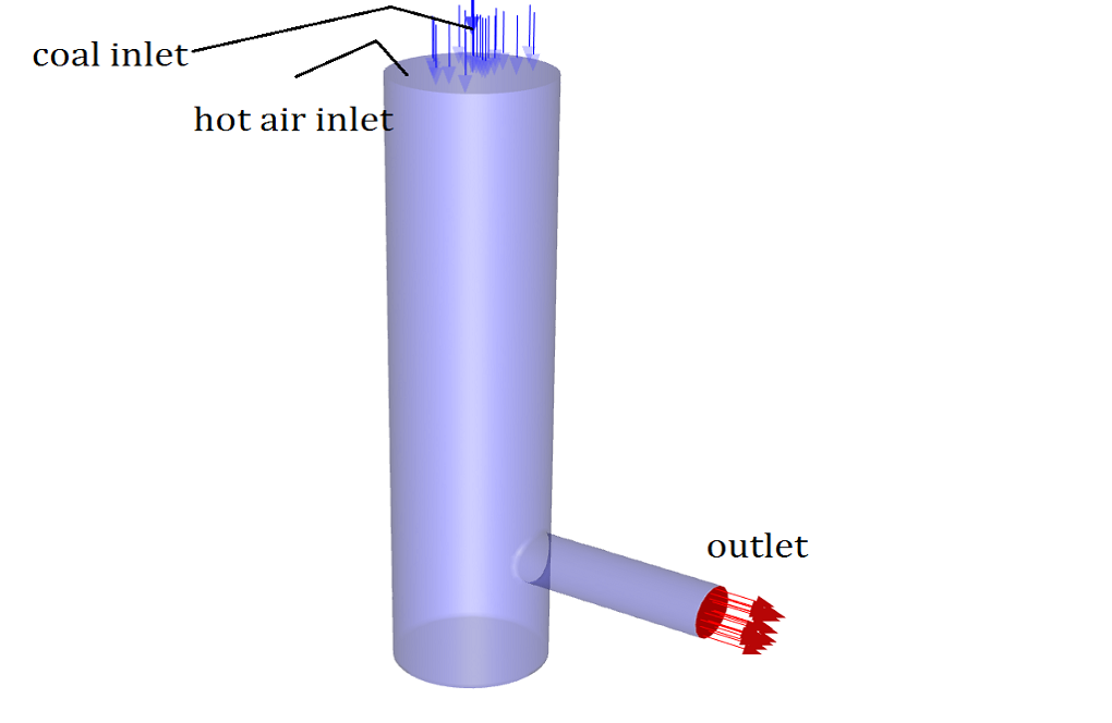
In this project, a combustion reaction is simulated inside a combustion chamber by ANSYS Fluent software. The volatile coal mixture in a gaseous state enters the combustion chamber and mixes with high-temperature airflow (1623 K). As a result, the combustion process takes place. This process will also result in different productions, including pollutants like NOx, SOx, etc., which will be analyzed in this project. The energy equation is activated. K-epsilon Standard viscosity model is used to analyze the mixture’s turbulence, and standard wall function is exploited for the regions near the walls.
The species transport model is used to analyze the combustion process. The finite rate Eddy Dissipation method has been used to investigate the chemical-turbulent interaction of combustion reactants, and NOx, SOx, and soot models are activated, and the algebraic approach is used for Turbulence Interaction mode. The ideal gas equation has also been used to determine the density changes due to temperature changes.
Combustion Chamber Geometry & Mesh
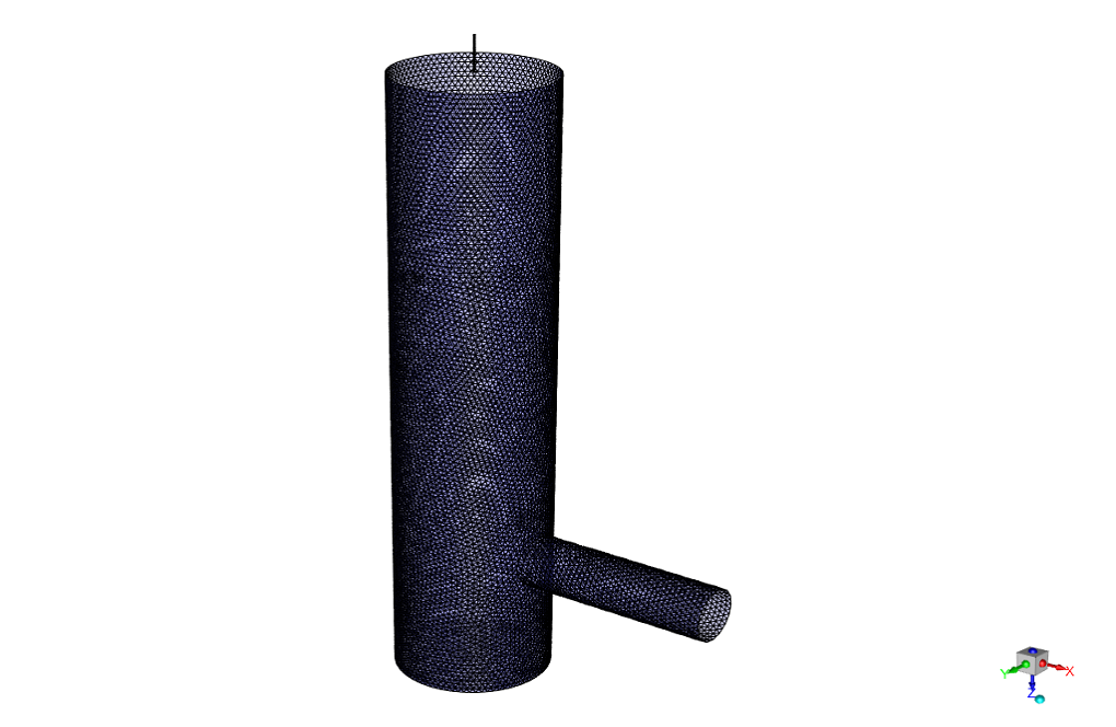
This project’s geometry is designed and meshed inside the ANSYS design modeler and meshed in ANSYS meshing software. The mesh type used for this geometry is unstructured, and the total element number is 508367.

 Pollutant Prediction CFD Simulation Settings
The critical assumptions considered in this project are:
- Simulation is done using a pressure-based solver.
- The present simulation and its results are considered steady and do not change as a function of time.
- The effect of gravity has not been taken into account.
The applied settings are recapitulated in the following table.
| Models | ||
| Viscous model | k-epsilon | |
| k-epsilon model | standard | |
| near-wall treatment | standard wall function | |
| Energy | on | |
| Species | Species transport | |
| Reactions | Volumetric | |
| Chemistry solver | None-explicit source | |
| Option | Diffusion energy source | |
| Mixture material | Coal-volatiles-air | |
| Turbulence chemistry interaction | Finite rate/Eddy-dissipation | |
| NOx mode | on | |
| Pathways | Thermal NOx + Prompt NOx+Fuel NOx+N2O intermediate | |
|
Turbulence interaction mode |
PDF mode | Temperature/species |
| PDF type | beta | |
| Temperature variance | algebraic | |
| Formation model parameters | ||
| thermal | [O] model | equilibrium |
| Prompt | Equivalence ratio | 1 |
| SOx Formation | on | |
|
Turbulence interaction mode |
PDF mode | Temperature/species |
| PDF type | beta | |
| Temperature variance | algebraic | |
| Soot Model | One-step | |
| Boundary conditions | ||
| Inlet | velocity inlet | |
|
Coal inlet |
Velocity magnitude | 30 m/s |
| Thermal | 300 K | |
| Species (mass fraction) | vol à 1 | |
|
Hot air inlet |
Mass flow rate | 0.031944 Kg/s |
| Thermal | 1623 K | |
| Species (mass fraction) | O2 à 0.21 | |
| Outlet | Pressure outlet | |
| Gauge pressure | 0 Pa | |
| Walls | ||
| wall motion | stationary wall | |
| Heat flux | 0 W/m2 | |
| Species (boundary condition) | Zero diffusive flux | |
| Solution Methods | ||
| Pressure-velocity coupling | SIMPLE | |
| Spatial discretization | pressure | standard |
| momentum | first order upwind | |
| energy | second order upwind | |
| turbulent kinetic energy | first order upwind | |
| turbulent dissipation rate | first order upwind | |
| Species | second order upwind | |
| Pollutants | second order upwind | |
| Initialization | ||
| Initialization method | Standard | |
| gauge pressure | 0 Pa | |
| velocity (x,y,z) | (0,0,1.035874) m/s-1 | |
| temperature | 1423 K | |
| Turbulent kinetic energy | 0.000643821 m2/s2 | |
| Turbulent dissipation rate | 0.0001817394 m2/s3 | |
| O2 | 0.21 | |
| Other species | 0 | |
| pollutants | 0 | |
Results & discussion
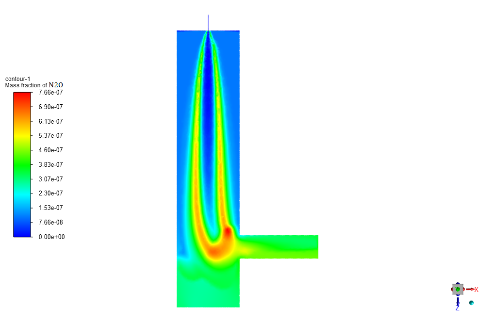
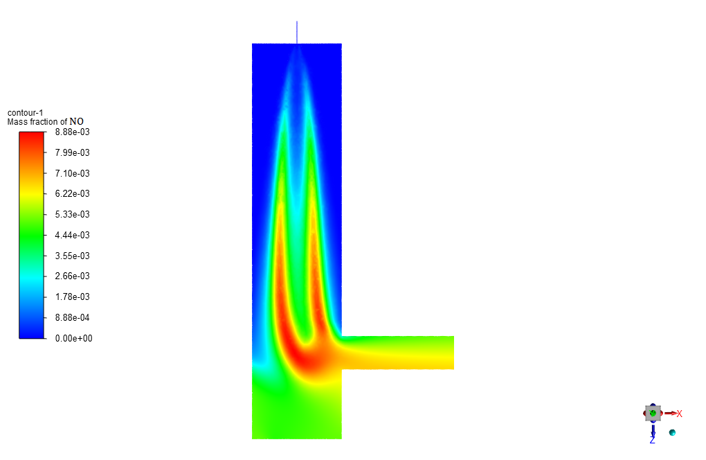
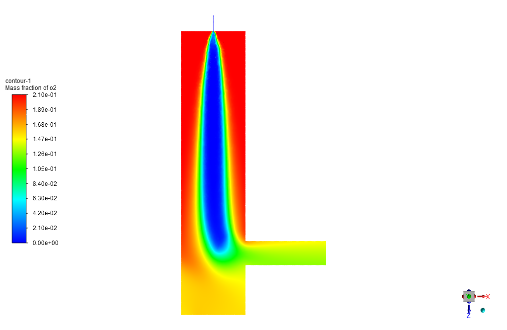
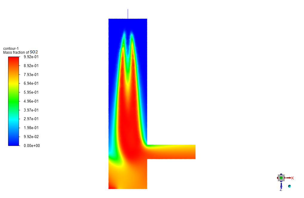
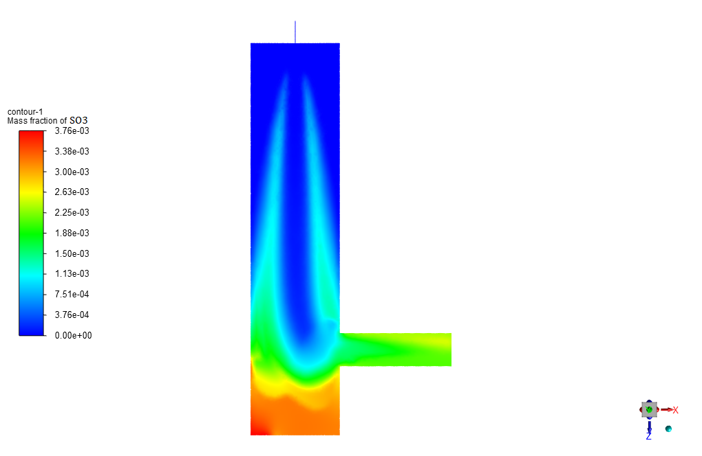
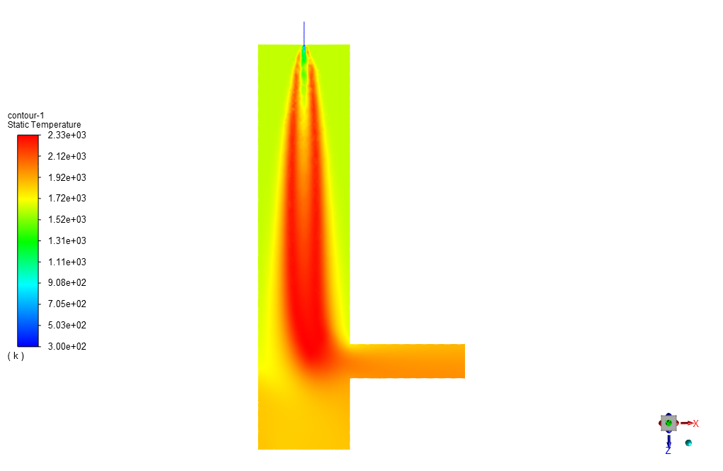
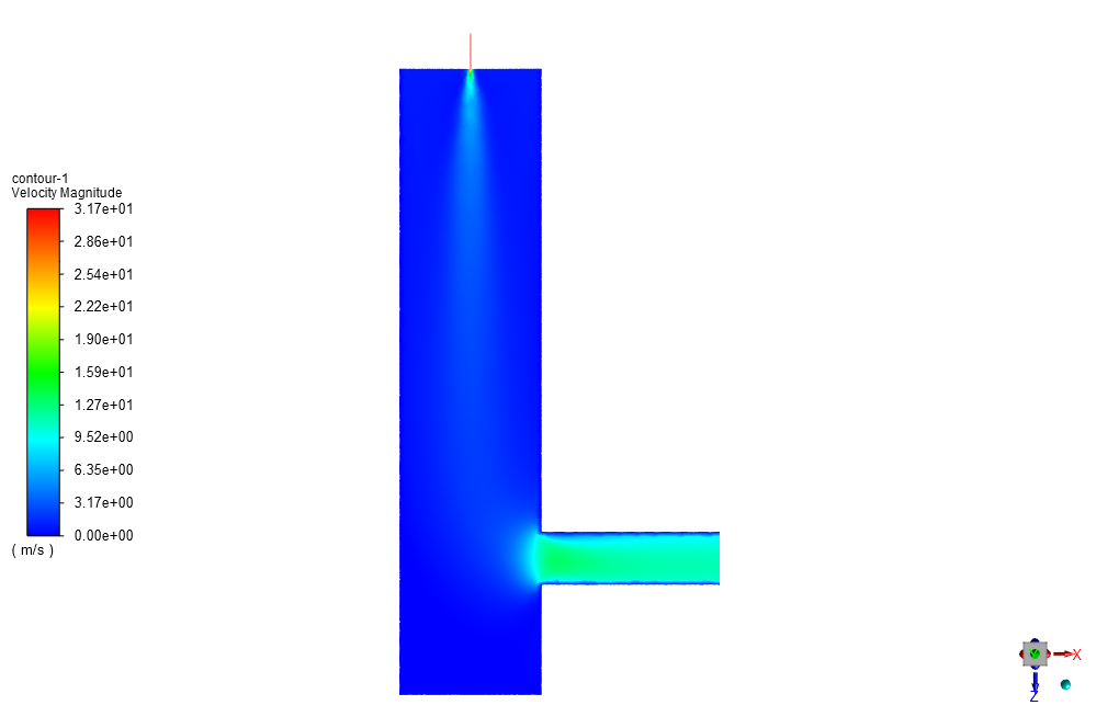
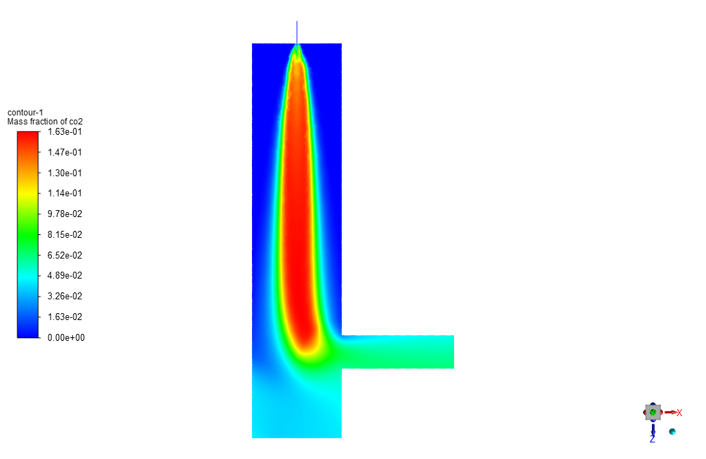
When comparing two contours of temperature and NO mass fraction, it can be easily observed that the NOx pollutant is mostly generated at places where the flame has its highest temperature. One way to reduce the generation of this pollution is to reduce the effective temperature of combustion and flame. However, it should be mentioned that lowering the flame temperature will result in an increased amount of generated soot near the flame’s advancing edges.
You can obtain Geometry & Mesh file, and a comprehensive Training Movie which presents how to solve the problem and extract all desired results.


 Pollutant Prediction CFD Simulation Settings
Isabella Balistreri –
this is a amazing software
Raheem Paucek –
What is the significance of simulating the combustion process in a gas turbine?
MR CFD Support –
Simulating the combustion process in a gas turbine is crucial to optimize fuel efficiency, reduce pollutant emissions, and improve overall performance.
Miss Nelle Haag II –
How do you model the combustion process in these simulations?
MR CFD Support –
We use a combustion model in ANSYS Fluent, which allows us to simulate the chemical reactions occurring in the combustion chamber and predict the temperature, pressure, and species concentration.
Miss Ashley Wyman –
What software do you use for these simulations?
MR CFD Support –
We use ANSYS Fluent software for our CFD simulations. It provides robust and accurate solutions for a wide range of fluid flow and heat transfer problems.
Genesis Roob –
I appreciate the complex analysis provided on NOx formation in the combustion process. It’s amazing how temperature control can reduce pollutants yet have other trade-offs like increased soot production.
MR CFD Support –
Thank you for your insightful comment. We’re glad you recognized the nuanced balance between temperature control and pollutant formation in combustion processes. Understanding these trade-offs is crucial for developing more efficient and cleaner combustion systems.
Jerod Ziemann –
What a comprehensive simulation project! The details on how ANSYS Fluent is used to predict pollutant concentrations in combustion scenarios is highly valuable. The inclusion of how temperature variations affect NOx levels and subsequent soot production offers insightful nuances into the combustion process. Kudos to the MR CFD team for such an elaborate depiction of combustion analysis through CFD simulations.
MR CFD Support –
Thank you for your positive feedback! We’re glad you appreciate the depth and complexity of the combustion simulation training. It’s always our goal to provide informative and valuable content that can assist in understanding the intricacies of CFD analysis. If you have any further inquiries or want to explore more about our simulation training products, please don’t hesitate to reach out.
Margarett Reynolds –
The learning was excellent and provided extensive insight into combustion simulations. What would be the recommended approach to reduce pollutants in this scenario keeping the energy efficiency in check?
MR CFD Support –
Glad to hear you found the training insightful. To reduce pollutants like NOx while maintaining energy efficiency, you could leverage combustion-control technologies like staging the air or fuel supply, or optimizing the burner geometry to maintain a lower peak flame temperature. This would limit NOx formation. Additionally, implementing post-combustion treatments such as selective catalytic reduction (SCR) could further reduce NOx emissions without compromising energy efficiency.
Mr. Baylee Pacocha Jr. –
I am thrilled with the level of detail in the pollutant prediction CFD simulation training. The inclusion of NOx, SOx, and soot models helps to foster a deep understanding of the complexities of real-world combustion scenarios. Learning how to manipulate combustion conditions to reduce pollutants while balancing the resulting trade-offs with soot production was particularly enlightening. The training materials have definitely enhanced my knowledge in combustion simulations. Great job, MR CFD!
MR CFD Support –
Thank you so much for the heartfelt review! We’re very pleased to hear that our simulation training has helped deepen your understanding of combustion processes and pollutant formation. If you ever have any more questions or need further assistance, don’t hesitate to reach out. We wish you all the best with your future combustion simulation projects!
Jannie Fritsch III –
I was truly impressed by the attention to detail for pollutant prediction in this CFD simulation. The balance between combustion efficiency and pollutant control was highlighted well. The advising on temperature control as a method to reduce NOx formation without an overwhelming increase in soot was particularly insightful.
MR CFD Support –
Thank you for your positive feedback on the Combustion Chamber pollutant prediction simulation training. We’re glad you found the content insightful and useful for understanding the complex balance between combustion efficiency and environmental considerations. It’s our aim to provide detailed and practical analysis in our simulations. Your appreciation is highly valued!
Spencer Feeney –
The tutorial mentioned predicting NOx pollution by examining temperature contours. Does the soot model impact NOx production predictions, and if so, how?
MR CFD Support –
The soot model, which predicts the amount of soot generated during combustion, does impact the NOx production predictions indirectly. Soot can influence the radiation heat transfer in the combustion chamber, and since temperature is a crucial factor in the formation of NOx, any change in heat transfer dynamics can affect the NOx production. Moreover, reducing flame temperature to lessen NOx creation can, in turn, elevate soot formation at different zones of the combustion chamber. The interactions between soot, temperature, and NOx formation are complex and all these factors must be considered for accurate predictions.
Carroll Fritsch V –
I found the details on pollutant production very enlightening. It’s good to know that temperature plays a crucial role in NOx generation. Thank you for a fantastic product.
MR CFD Support –
Thank you for your positive feedback! We’re glad that you found the details on pollutant production helpful and insightful. It’s our pleasure to provide quality educational products that contribute to better learning outcomes. If you have any more questions or need further assistance with our products, feel free to reach out. Happy learning!
Brittany Welch –
The balancing act between controlling NOx and soot in the combustion process is fascinating. Is it possible to achieve a reduction in both pollutants concurrently, or does reducing one typically increase the other?
MR CFD Support –
Reducing NOx tends to result in higher soot formation and vice versa, due to the trade-off between flame temperature and available oxygen. Lowering flame temperature can lead to less NOx but more soot formation, while ensuring complete combustion with higher temperatures and enough oxygen can reduce soot at the expense of increasing NOx emissions. Advanced combustion techniques and after-treatment technologies are being developed to reduce both pollutants concurrently.
Prof. Sabryna Boyle I –
The training package seems comprehensive. Are specific methodologies used in the ANSYS Fluent software to predict soot in addition to NOx and SOx pollutants, which is not mentioned in the detail?
MR CFD Support –
Yes, the soot model is part of the pollutant prediction strategies in the simulation. The One-step model for soot formation and oxidation is used in conjunction with NOx and SOx models within the comprehensive pollutant prediction approach in ANSYS Fluent. The software has capabilities for soot modeling that work together with other combustion and emission analyses.
Clarabelle Roob –
The description was quite thorough and educational. One can clearly perceive the comprehensive approach taken to predict pollution within the combustion chamber with precision. The consideration of various NOx pathways, alongside measures like soot modeling, indicates a depth of simulation that could yield actionable insights for pollution control in combustion processes.
MR CFD Support –
Thank you very much for your positive feedback! We’re thrilled to hear you found the simulation details and prediction capabilities for pollution control within a combustion chamber comprehensive and insightful. It’s our goal to provide detailed and actionable data through our CFD simulations. If you ever have any more questions or need further assistance with related simulations, don’t hesitate to reach out to us. Your interest in applying this knowledge for combustion process improvement is exactly what drives us to keep refining our simulation methodologies. Thank you for choosing MR CFD for your learning journey!
Jackson Dare Sr. –
I’m thrilled with the training! The pollutant prediction in a combustion chamber was complicated, but your CFD simulation provided a practical understanding. It’s impressive to see the correlations between temperature and NOx levels. Has this training been beneficial for those in the industry concerned with reducing emissions from combustion processes?
MR CFD Support –
Thank you for your wonderful feedback! We’re delighted to hear that you found our CFD Simulation training on pollutant prediction in a combustion chamber useful. It’s gratifying to know that our program could illustrate the complex relationship between temperature and pollutant generation effectively. Yes, this training is indeed geared towards professionals in the industry looking to reduce emissions. It provides insightful data and methodologies that are invaluable for developing strategies to minimize environmental impact while still achieving efficient combustion. If you have any further questions or need assistance with implementing the strategies outlined in our training, don’t hesitate to reach out.
Alana Waters –
I’m really enthusiastic about the approach used for predicting pollutants in this simulation. I have always been curious – How effective is the Finite Rate/Eddy Dissipation model when compared to other models for this kind of analysis?
MR CFD Support –
We’re glad to hear positive feedback on our approach. The Finite Rate/Eddy Dissipation model effectively couples the turbulent flow field with chemical reaction rates, making it a suitable choice for combustion analysis where turbulence significantly influences reaction rates. Compared to other models, it occupies a middle ground between accuracy and computational efficiency, providing enough detail for many practical combustion scenarios while not being as computationally demanding as more sophisticated models.