Gas Liquid Separator CFD Simulation, ANSYS Fluent Tutorial
$120.00 Student Discount
- The problem numerically simulates a Gas-Liquid Separator using ANSYS Fluent software.
- We design the 3-D model by the Design Modeler software.
- We Mesh the model by ANSYS Meshing software, and the element number equals 356230.
- We use the VOF Multi-phase model to define Hydrogen-sulfide and Oil in the chamber.
To Order Your Project or benefit from a CFD consultation, contact our experts via email ([email protected]), online support tab, or WhatsApp at +44 7443 197273.
There are some Free Products to check our service quality.
If you want the training video in another language instead of English, ask it via [email protected] after you buy the product.
Description
Description
This simulation is about a Gas-Liquid Separator via ANSYS Fluent software. We perform this CFD project and investigate it by CFD analysis. A gas-liquid separator is used in several industrial applications to separate a vapor-liquid mixture. A vapor-liquid separator may be called a flash drum, break-pot, knock-out drum, or knock-out pot.
It is often called a demister when used to remove suspended water droplets from streams of air. Separation is the fluid process in which mixtures of materials in gaseous, liquid, and solid forms are separated. The crude gas entering the refinery usually contains gas, Oil, and solids and must be separated before being subjected to special operations. Oil and gas separators are one of the main gas/liquid separators used in oil/gas wells to separate gas, crude Oil, and water from the stream in the well.
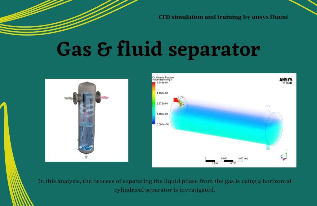
Gas oil separators can be made vertically, horizontally, or spherically, but the most common type is horizontal. In this analysis, the process of separating the liquid phase from the gas using a horizontal cylindrical separator is investigated. The mixture of Oil and gas (with mass flow rates of 3kg/s and 0.15kg/s, respectively) enters the separator, and since the Oil is heavier than the gas, it settles down while the gas phase exits from the top outlet.
The geometry of the present model is drawn by Design Modeler software. The geometry of this model consists of a horizontal cylinder. It has a horizontal inlet for mixture flow and two vertical outlets for separated gas and liquid flows. The model is then meshed by ANSYS Meshing software. The model mesh is unstructured, and 356230 cells have been created.
Gas Liquid Separator Method
This simulation uses the Multi-phase model for modeling two phases of oil and hydrogen sulfide. Since the phase separation boundary is completely distinct, the Volume of Fluid (VOF) model is used.
Hydrogen sulfide is defined as the primary phase, and Oil as the secondary phase. The dispersed type in interface modeling has been used to determine the behavior at the boundary between two phases.
Gas Liquid Separator Result
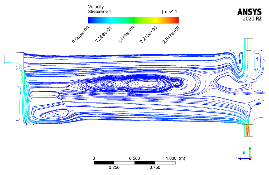
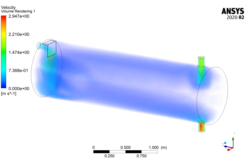
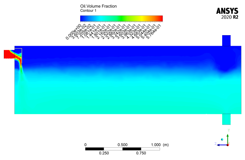
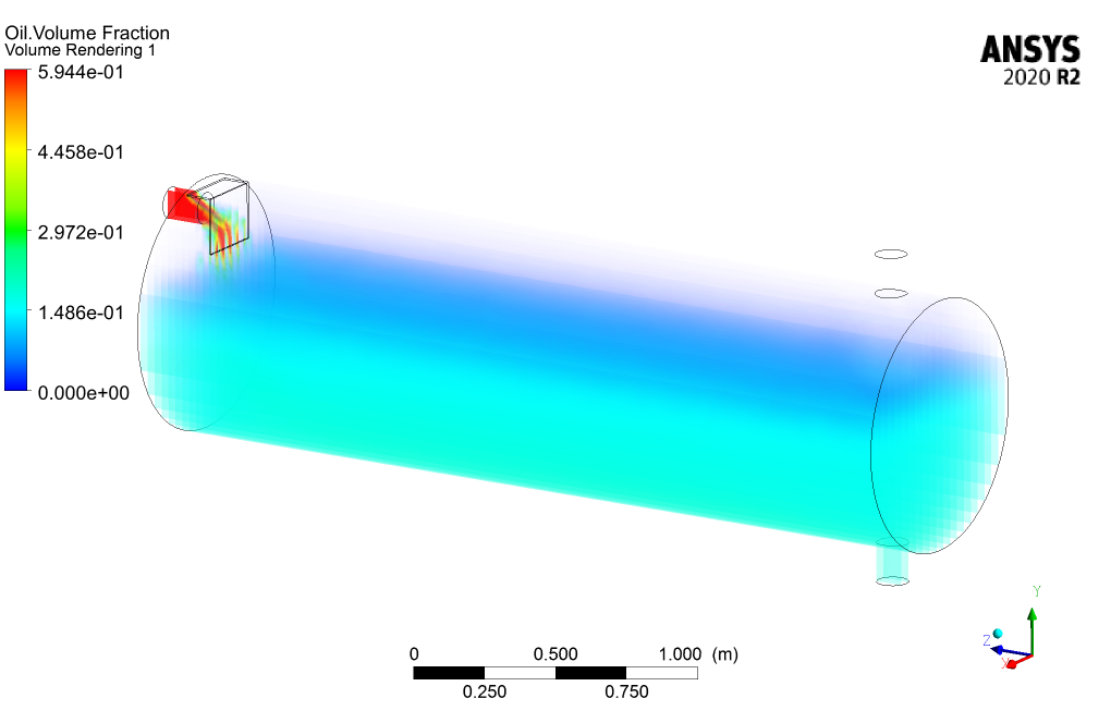
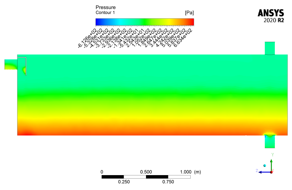
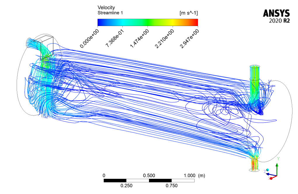
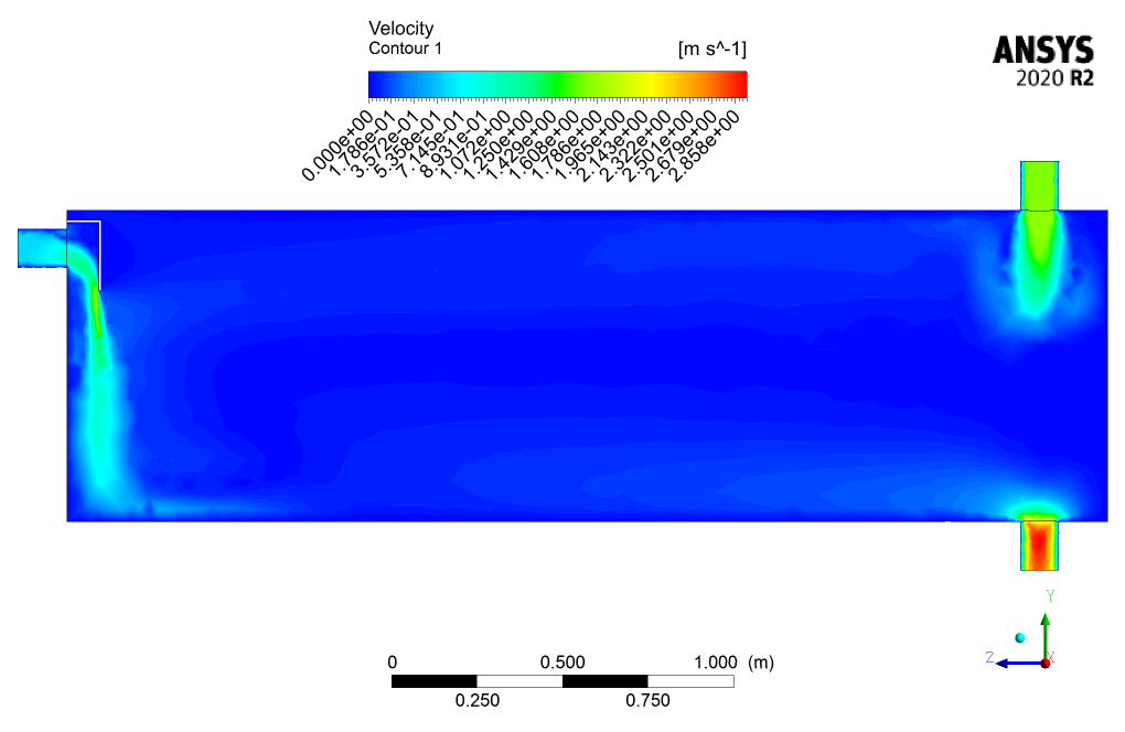
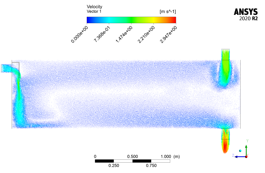
After simulation, 2D and 3D contours of velocity, pressure, and mass fraction of Oil and gas are obtained. Also, the velocity vector and streamline inside the separator are obtained.
The results show that the Oil settles in the lower part of the separator. Oil goes to the bottom of the chamber due to its heaviness, and hydrogen sulfide goes to the top of the chamber due to its lightness. So it can be concluded that this separator system works well and correctly separates oil and gas phases.

Jaclyn Langworth –
The tutorial was really thorough and the results section clearly explained how effective the separator is. Great work on demonstrating the separation process in the simulation!
MR CFD Support –
Thank you for your positive feedback. We’re delighted to hear that you found the tutorial thorough and that the explanation of the results was clear. It’s our goal to provide informative and helpful simulations. We appreciate your support and are glad the simulation was beneficial for you!
Stanton Lang –
Fantastic tutorial for understanding gas-liquid separation processes! I’ve gained practical knowledge for my applications, and the clarity in explaining VOF model application was beneficial.
MR CFD Support –
Thank you for your kind review! We’re thrilled to hear the tutorial was not only informative but also clear and applicable to your work. We always strive to provide valuable insights for our users. If you ever have any more questions or need further assistance, we’re here to help!
Wade Gaylord V –
The simulation looks thorough. I was wondering about post-processing the results; how easy is it to visualize the separate phases in ANSYS Fluent?
MR CFD Support –
In ANSYS Fluent, visualizing separate phases is straightforward using the post-processing tools available. You can utilize contour plots with phase-specific variables or mass fractions to clearly display each phase’s distribution. Additionally, phase volume fraction contours paired with velocity vectors and streamlines illustrate phase separation effectively.
Wilfredo Hirthe –
I appreciate the thoroughness with which the CFD project on the Gas-Liquid Separator was investigated using ANSYS Fluent. The inclusion of 2D and 3D contours for velocity, pressure, mass fractions, and streamlines provided a comprehensive understanding of the separator’s effectiveness. Fantastic teaching aid!
MR CFD Support –
Thank you for your positive feedback! We’re glad to hear that our Gas-Liquid Separator simulation and tutorial met your expectations and provided comprehensive insights. We strive to deliver detailed and useful CFD analyses to help with engaging learning experiences. Your satisfaction with the project is very important to us.
Aniya Wisozk DVM –
I’m grateful to have found such an insightful tutorial on Gas-Liquid Separator simulation. The level of detail brings clarity to the complex concepts of multiphase separation. I especially appreciated the clear outlines of the results which grew my understanding of gas and liquid behavior within the separator.
MR CFD Support –
Thank you for your positive review! We’re delighted to hear the tutorial was able to enhance your understanding of multiphase separation and that you found the detailed results helpful. If you have further inquiries or need additional information on similar topics, please don’t hesitate to reach out to us.
Celestino Bednar III –
Just wanted to say the tutorial for the Gas-Liquid Separator simulation on ANSYS Fluent was so helpful! The steps provided made the process very understandable, and the explanation of the concepts involved was clear. I now feel comfortable setting up and analyzing gas-liquid systems. The visualization of the phase separation in the results was particularly impressive. Keep up the great work!
MR CFD Support –
Thank you so much for your kind words! We’re thrilled to hear that our tutorial was helpful and made you feel comfortable with gas-liquid separation simulations in ANSYS Fluent. We strive to provide clear and concise guidance to help users like you achieve great results. Your feedback is greatly appreciated, and we look forward to bringing you more valuable learning materials. Thanks for choosing our tutorial, and don’t hesitate to reach out if you have any more questions or need further assistance in the future!
Horacio Koepp –
I appreciated the detailed explanation of the system being modeled. Just wondering, did the simulation account for possible turbulence within the gas liquid separator, and if so, how was this modeled in ANSYS Fluent?
MR CFD Support –
Thank you for your compliment and for your interest in the details of the simulation. Yes, the simulation accounted for possible turbulence within the gas liquid separator. In ANSYS Fluent, turbulence is typically modeled using appropriate turbulence models such as the k-epsilon or k-omega models, depending on the flow characteristics. These models help in predicting the eddy viscosity and turbulent kinetic energy which are crucial for capturing the complex flow behavior in such systems. For specifics on which turbulence model was chosen for this particular simulation, please refer to the tutorial documentation where the choice of turbulence model will be thoroughly explained, considering the physics of the situation and the required accuracy.
Ross Mayer –
Which specific interface modeling technique was used for the boundary between the oil and hydrogen sulfide phases, and why was this choice made?
MR CFD Support –
The dispersed type in interface modeling has been used to determine the boundary between the oil and hydrogen sulfide phases within the volume of the fluid (VOF) model. This choice was likely made to accurately capture the behavior where the two fluids interact, especially given their differing densities and the clear boundary that is expected between a liquid and a gas in a gravity-driven separation process.
Delmer Schmidt –
I’ve read about the use of the VOF model for the gas liquid separator. Can you tell me more about when it’s appropriate to use this type of model?
MR CFD Support –
The Volume of Fluid (VOF) model is particularly suitable when the phase interface is sharp, and the topology of the interface between phases is critical for simulation predictions. The VOF model tracks and locates the interface between liquids or between a liquid and a gas, thus it is often used in simulations like separators where distinct phase separation is present and accurate phase interaction modeling is important.
Callie Lynch –
I’m so impressed with the level of detail in the simulation results! It really seems like the MR CFD product for the Gas Liquid Separator CFD Simulation walks you through every step with clarity. The use of ANSYS Fluent is demonstrated very capably for such a complex multiphysics scenario.
MR CFD Support –
Thank you for your positive feedback! We are delighted to hear that you appreciate the depth and clarity of the tutorial. Our goal is always to provide comprehensive and understandable content that aids our users in mastering complex simulations with ANSYS Fluent. Feel free to reach out with any more feedback or queries!
Trystan Goyette –
The tutorial was enlightening! Thanks for the clarity on how gas-liquid separators work. Just one compliment – the visuals were especially helpful in understanding the flow patterns within the separator.
MR CFD Support –
Thank you for your kind words! We are very pleased to hear that our tutorial was able to provide clarity on gas-liquid separator function and that the visual aids were beneficial to your understanding. We strive to deliver comprehensive and intuitive learning materials, and your compliment reinforces our commitment to quality educational content.
Dr. Addie Harvey –
I was impressed with the clarity of the simulation results for phase separation. Can you detail how the volume fraction contours help in understanding the separation efficiency?
MR CFD Support –
The volume fraction contours in the simulation display the distribution of each phase within the separator. High-quality contours allow for a clear distinction between the Oil and gas phases, making it easier to visualize the separation process as heavier Oil settles and lighter gas rises. The contours directly reflect the efficiency of the separator and validate the effectiveness of the design and operation parameters.
Prof. Octavia Schmitt DDS –
I am thoroughly impressed with the level of detail in the Gas Liquid Separator CFD Simulation tutorial. The step-by-step process was easy to follow and the included screenshots made my learning experience very smooth. One thing that stood out to me was how well the separation phenomenon was explained with regards to the density difference between gas and liquid. A great educational resource indeed!
MR CFD Support –
Thank you for your kind words! We are delighted to hear that you found the tutorial easy to follow and educational. We strive to provide clear and comprehensive instructions complemented by visual aids to enhance learning, so we’re glad this was reflected in your experience. If there’s any other aspect of CFD you’re curious about or another product you wish to explore, feel free to reach out or browse our website for more offerings. Thank you for choosing MR CFD Company for your learning journey. We hope to continue supporting your development in CFD.
Libbie Turner –
Is the simulation capable of identifying scenarios where the oil and gas do not separate efficiently, or does the current setup always assume successful separation?
MR CFD Support –
The simulation is designed to assess the separation performance of the gas-liquid separator. It can highlight inefficiencies or the failure to properly separate the two phases by examining the velocity, pressure, and mass fraction results. Discrepancies in the expected behavior can be investigated to understand and mitigate potential separation issues.
Dave Monahan –
Just wanted to say that the tutorial for the Gas-Liquid Separator CFD Simulation was incredibly helpful! The detailed explanation on setting up the Multi-phase model using the VOF method was exactly what I needed for my own project. The inclusion of velocity vectors and streamline results really helped visualize the separation process. Thanks for a great learning resource!
MR CFD Support –
Thank you for taking the time to write such a positive review! We are delighted to hear that our Gas-Liquid Separator tutorial met your expectations and provided you with the detailed information and visualization you needed for your project. If you have any further questions or need more assistance, feel free to reach out. Your success is our greatest reward, and we look forward to supporting your future CFD endeavors.
Ms. Pinkie Ledner III –
Could this CFD simulation be adapted to work for different fluid mixtures other than Oil and hydrogen sulfide, such as water and air?
MR CFD Support –
Yes, the CFD simulation for a Gas-Liquid Separator can be adapted to different fluid mixtures like water and air. The principles behind the separation process are similar, and it would primarily require changing the material properties and possibly the operating conditions to match the characteristics of the new fluid mixture.
Ernestina Rice –
I’m impressed with how the Gas Liquid Separator simulation accounts for the differing densities of Oil and gas to ensure their separation. The detailed analysis of velocity and mass fraction indicates a thorough investigation.
MR CFD Support –
Thank you for your positive feedback! We’re glad that the detailed analysis in the simulation project on the Gas Liquid Separator could clearly demonstrate the effectiveness of separating Oil and gas based on their densities. If you have any more questions or need further information on similar simulations, don’t hesitate to reach out!
Reyna Buckridge –
I thoroughly enjoyed the Gas-Liquid Separator simulation tutorial! It was comprehensive and I now understand how to set up and analyze such a system in ANSYS Fluent. The unstructured mesh guidance was especially helpful!
MR CFD Support –
Thank you for the kind words! We are pleased to hear you found the Gas-Liquid Separator simulation tutorial comprehensive and helpful. If you have any further questions or need additional guidance, don’t hesitate to reach out!