Fuel Injector CFD Simulation, Three-Phase Flow (Mixture Model)
$80.00 $40.00 Student Discount
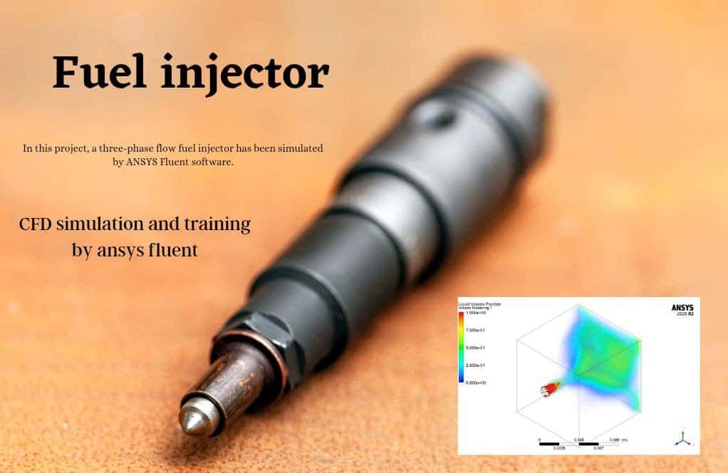
- The problem numerically simulates the Fuel Injector using ANSYS Fluent software.
- We design the 3-D model by the Gambit software.
- We Mesh the model by Gambit software.
- The Mesh type is Structured, and the element number equals 932107.
- We use the Mixture Multi-Phase model to define three phases: air, liquid and vapor.
To Order Your Project or benefit from a CFD consultation, contact our experts via email (info@mr-cfd.com), online support tab, or WhatsApp at +44 7443 197273.
There are some Free Products to check our service quality.
If you want the training video in another language instead of English, ask it via info@mr-cfd.com after you buy the product.
Description
Fuel Injector CFD Simulation, Three-Phase Flow, ANSYS Fluent Tutorial
This simulation is about a Fuel Injector via ANSYS Fluent software. We perform this CFD project and investigate it by CFD analysis.
In general, a fuel injector is a system of ducting and nozzles used to direct the flow of a high-pressure fluid so that a lower-pressure fluid is entrained in the jet and carried through a duct to a region of higher pressure. It is a fluid-dynamic pump with no moving parts except a valve to control inlet flow.
A steam injector is a typical application of the principle used to deliver cold water to a boiler against its pressure, using its own live or exhaust steam, replacing any mechanical pump.
In this project, a three-phase flow fuel injector has been simulated. This mixture consists o liquid, air, and vapor. The liquid will enter the computational zone through the injector at the velocity of 20m/s, and a jet flow has been formed inside.
The geometry of the present model is drawn by Gambit software. The geometry of this model consists of a combustion chamber, including a fuel injector and an air entrance.
The model is then meshed by Gambit software. The model mesh is Structured, and 932107 cells have been created.
Fuel Injector Method
In this simulation, three fluids are used in the computational zone. These three phases include air, liquid, and steam.
Then the multiphase model is used. Since the separation boundary between the phases is unclear, the mixture model is used. In this multiphase model, the phases are completely mixed. Air is defined as the primary phase, and vapor and liquid as the secondary phase.
Fuel Injector Result
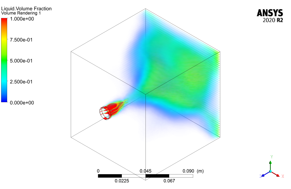
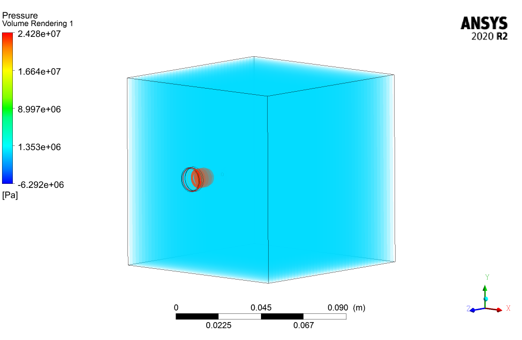
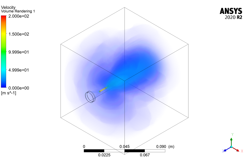
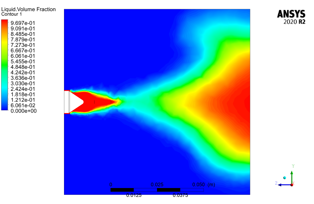
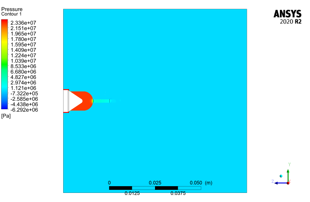
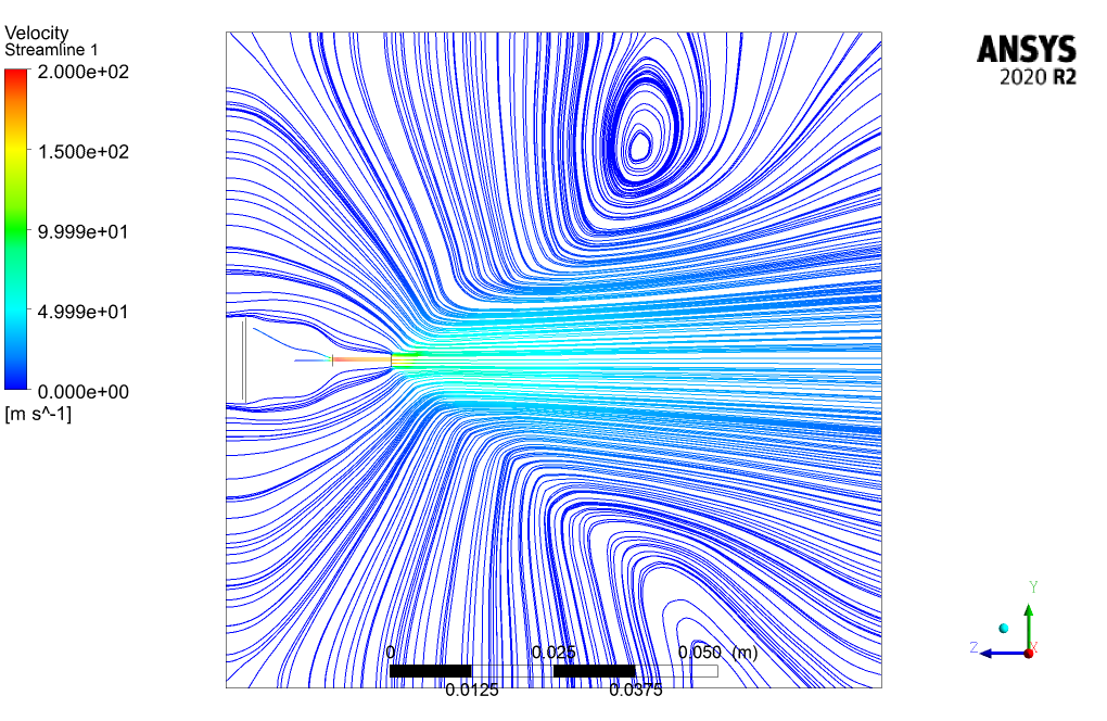
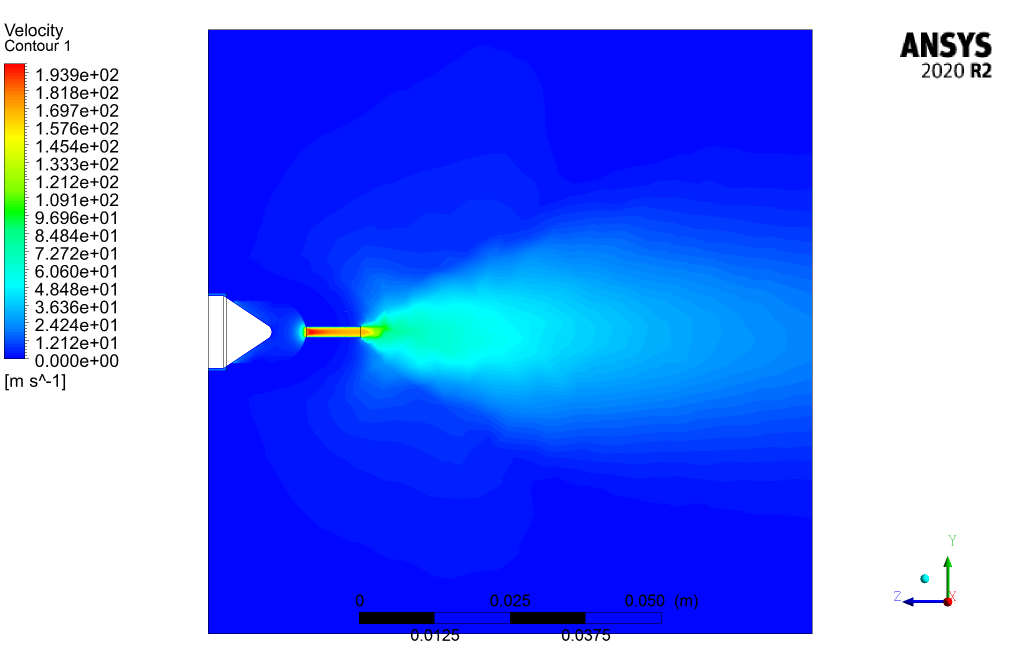
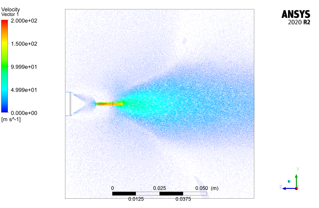
After simulation, the contours of pressure, velocity, and mass fraction of liquid, air, and vapor are obtained. The contours indicate that the liquid flow enters the combustion chamber at high speed and pressure and then spreads completely inside this space.
The contour comparison of each phase of the mixture confirms that the multiphase flow modeling has been performed correctly.

Laurianne Langosh PhD –
The tutorial was incredibly comprehensive. The step-by-step process for the fuel injector simulation gave me a deep understanding of three-phase flow in ANSYS Fluent. The attention to detail was impressive, especially regarding the mixture model and phase interaction!
MR CFD Support –
Thank you so much for your positive feedback! We’re thrilled to hear that our Fuel Injector CFD Simulation tutorial was able to provide you with a thorough understanding of three-phase flow and that our detailed approach met your expectations. Your satisfaction is our top priority, so it’s rewarding to know we hit the mark for you. If you need further assistance or have more questions in the future, please don’t hesitate to reach out.
Johan Reynolds –
I found the tutorial very insightful! I’m curious about how the multiphase mixture model accounts for the interaction between the liquid, air, and vapor. Could you elaborate on that?
MR CFD Support –
In the mixture model used for this Fuel Injector CFD Simulation, interactions between the liquid, air, and vapor are calculated based on shared pressure and velocity fields. The phases are assumed to be fully interpenetrating and the momentum exchange is calculated considering drag forces and turbulent dispersion forces within the mixture. The continuous phase (air) carries the dispersed phases (liquid and vapor), and relative velocities are accounted for to simulate mixing and dispersion adequately.
Taryn Kutch –
I’m really impressed with the results of this simulation! It appears that the different phases interact in a well-defined manner. Can you provide some insights on how the mixing of the liquid, air, and vapor was simulated accurately considering their differences in properties?
MR CFD Support –
We’re thrilled to hear that you’re impressed with our Fuel Injector simulation! The accurate simulation of the mixing process between the liquid, air, and vapor phases was achieved using the mixture model within ANSYS Fluent. This approach allows us to simulate the interaction between phases when their separation boundary isn’t sharply defined. The differing properties of each phase are taken into account through the definition of individual phase properties and interaction laws. This enables an accurate representation of the flow behavior for each phase and their influence on one another as they move through the injector and into the combustion chamber.
Lewis Kuhlman –
I was truly impressed with the detail in the CFD simulation for the Fuel Injector focused on a Three-Phase Flow. The complexity captured in the interplay between liquid, air, and vapor phases is commendable. It’s clear that a significant amount of work and expertise went into creating this accurate representation of a fuel injector system.
MR CFD Support –
Thank you so much for your positive feedback! We’re thrilled to hear that you appreciate the complexity and details of the Fuel Injector Three-Phase Flow simulation. A lot of effort goes into ensuring our analyses are as accurate and useful as possible. Your recognition of this is very encouraging for our team at MR CFD Company. If you have any further questions or need additional information on our products, please don’t hesitate to reach out.
Orion Armstrong –
I’m blown away by the detail included in the Fuel Injector three-phase flow simulation. The ability to see how the liquid, air, and vapor interact within the combustion chamber is invaluable for understanding the efficiency of the injector design. Great work on creating such a thorough and sophisticated simulation!
MR CFD Support –
Thank you for your wonderful review! We’re thrilled to hear that our Fuel Injector CFD Simulation has been valuable in providing detailed insights into the injector’s performance. It’s rewarding to see our efforts in creating an advanced simulation environment appreciated. Your feedback inspires us to keep delivering high-quality simulations for our users.
Mr. Torrey D’Amore –
I’m really impressed with the description of the CFD simulation for the fuel injector. The details on the multiphase flow and the depiction of how the injector works are fascinating. The use of structured meshing is also appreciated for its effectiveness in resolving the flow characteristics within the combustion chamber. Great to see such comprehensive analysis in the study of fluid dynamics; it prompts me to gain deeper insights into injector design and performance.
MR CFD Support –
Thank you for your kind words! We are delighted to know that the simulation met your expectations and provided valuable insights. It’s great to hear that our efforts in explaining the complex workings of the fuel injector and the nuances of three-phase flow have helped enhance your understanding. If you have further interests or need more information about CFD simulations, feel free to reach out to us.