
Solidification and Melting in Fuel Tank ANSYS Fluent CFD Simulation Tutorial
$120.00 Internship
- Solidification & Melting in a gasoline fuel tank is simulated by ANSYS Fluent.
- The geometry of the present model is drawn by Design Modeler software.
- The model is then meshed by ANSYS Meshing software, and the total number of cells is equal to 511821.
- The simulation is Transient.
To Order Your Project or benefit from a CFD consultation, contact our experts via email (info@mr-cfd.com), online support tab, or WhatsApp at +44 7443 197273.
There are some Free Products to check our service quality.
If you want the training video in another language instead of English, ask it via info@mr-cfd.com after you buy the product.
Description
Description
One of the disadvantages of frozen gasoline fuel is that the temperature drops during cold seasons or in cold places. When the gasoline temperature drops, sediments and adhesives are removed first. Then heavy hydrocarbon molecules begin to freeze and mummify as temperatures continue to decrease. To prevent the freezing of gasoline, it is necessary to raise the gasoline temperature in the fuel storage tanks. One way to increase the gasoline temperature in the fuel tank is to use pipes carrying the hot fluid flow. The use of helical tubes in situations where space constraints are due to greater heat transfer in a given space is particularly interesting. We designed the 3-D geometry of the model using Design Modeler software. The model consists of two main parts: a fuel tank and a spiral inner tube for hot water flow. We have used ANSYS Meshing software and unstructured mesh for the present model. The total number of cells is equal to 511,821.
Methodology
The present issue concerns the simulation of a gasoline fuel tank carrying a single-way reciprocating spiral tube passing through the tank. This inner tube carries a flow of water at a temperature higher than the temperature of the gasoline to increase the fuel temperature by creating heat transfer between the diesel and the water, thus preventing freezing inside the tank. Therefore, the present model uses a solidification and melting module for the simulation of the phase change material (PCM). The simulation is transient.
Conclusion
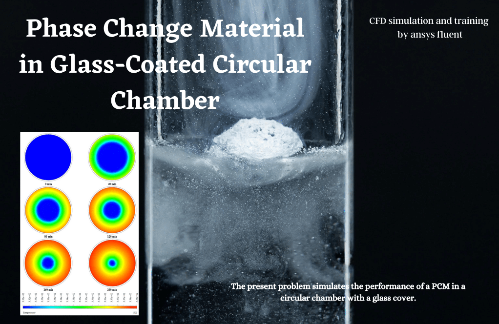
The maximum melting occurs near the helical pipes. So the liquid mass fraction will be increased as the heating process continues. This study is carried out in a limited time, and the results are obtained at the end of the simulation.
Reviews
You must be logged in to post a review.
Hilario Heathcote DDS –
Why do you use Design Modeler and ANSYS Meshing for your simulations?
MR CFD Support –
We chose Design Modeler and ANSYS Meshing because of their advanced capabilities and reliability. These tools allow us to create high-quality models and generate precise meshes, which are crucial for accurate simulations.
Ms. Chanel Wilderman –
It was pretty satisfying.
Odessa Abernathy –
I have a specific simulation in mind. Can you accommodate custom requests?
MR CFD Support –
Absolutely! We are always open to new ideas and would be happy to work on a custom simulation for you. Please feel free to share more details
Selmer Kub –
I found the description of using a spiral tube in the fuel tank to prevent gasoline freezing to be really innovative. The simulation approach is quite intriguing.
MR CFD Support –
Thank you for your positive feedback. We are pleased to hear that you found the simulation approach innovative and it provided valuable insights. We strive to develop simulations that meet real-world engineering challenges effectively.
Prof. Casandra Weissnat –
I’m amazed by this simulation studying solidification and melting! The idea of using helical tubes in a fuel tank is ingenious. Kudos to the MR CFD team for creating a detailed and enlightening tutorial.
MR CFD Support –
Thank you for your positive feedback! We’re thrilled to hear that you found our tutorial both educational and insightful. If you have any further questions or if there’s anything else we can help you with, please don’t hesitate to reach out.
Roberta Cole MD –
I found the concept of using helical tubes to prevent gasoline freezing fascinating. Do you provide the specific parameters for the water flowing through the pipes, such as the temperature and flow rate? This could be very useful for someone looking to replicate or understand the specifics of the process.
MR CFD Support –
Yes, the specific parameters of the water flow, like temperature and flow rate through the helical pipes, are included in the tutorial materials. It ensures a comprehensive understanding of how the simulation replicates the heat transfer necessary to prevent the gasoline from freezing.
Prof. Ricky Herman –
Your simulations are incredibly detailed. Great work!
MR CFD Support –
Thank you! We put a lot of effort into ensuring our simulations are as detailed and accurate as possible.
Mortimer Walsh –
This tutorial sounds very comprehensive. The way the heat transfer between diesel and water is modeled using helical tubes appears very technically innovative. Could you please share more detail on the specific heat transfer mechanisms that were considered in this simulation?
MR CFD Support –
In this CFD simulation, both conduction and convection heat transfer mechanisms are considered. Conduction accounts for the heat transfer within the solid regions of fuel that are experiencing phase change, while forced convection is at play within the helical pipes where the hot water is flowing. The influence of the warm water on the diesel temperature initiates the melting of the solid fuel, which is modeled using the solidification and melting module in ANSYS Fluent software.
Maximus Abshire –
The CFD tutorial on melting in a fuel tank was superb! I now thoroughly understand how to apply the solidification and melting principles in ANSYS Fluent. Above all, the spiral inner tube implementation was a clever approach that saved space while maximizing heat transfer.
MR CFD Support –
Thank you so much for your positive feedback! We strive to provide detailed and thoroughly planned CFD tutorials to help our users understand and apply critical concepts effectively. We’re thrilled to know you found the solidification and melting in a fuel tank simulation helpful, and that the spiral tube implementation in particular resonated with you. Your understanding of the principles and techniques is an excellent indicator that our tutorial has achieved its goal. We appreciate you taking the time to leave a review.
Gerry Dare DVM –
The module by MR CFD was clear and instructive – it simplified the complexity of simulating solidification and melting. I appreciated how it walked me through setting up a helical tube system to prevent fuel freezing. Great educational resource!
MR CFD Support –
Thank you for your kind word we are thrilled you found the Solidification and Melting in Fuel Tank simulation tutorial informative and accessible. At MR CFD, we strive to simplify complex CFD concepts for a broader understanding. We’re glad it was beneficial to your learning experience!