Hydraulic Jump Investigation in Stepped Structures, ANSYS Fluent
$80.00 Student Discount
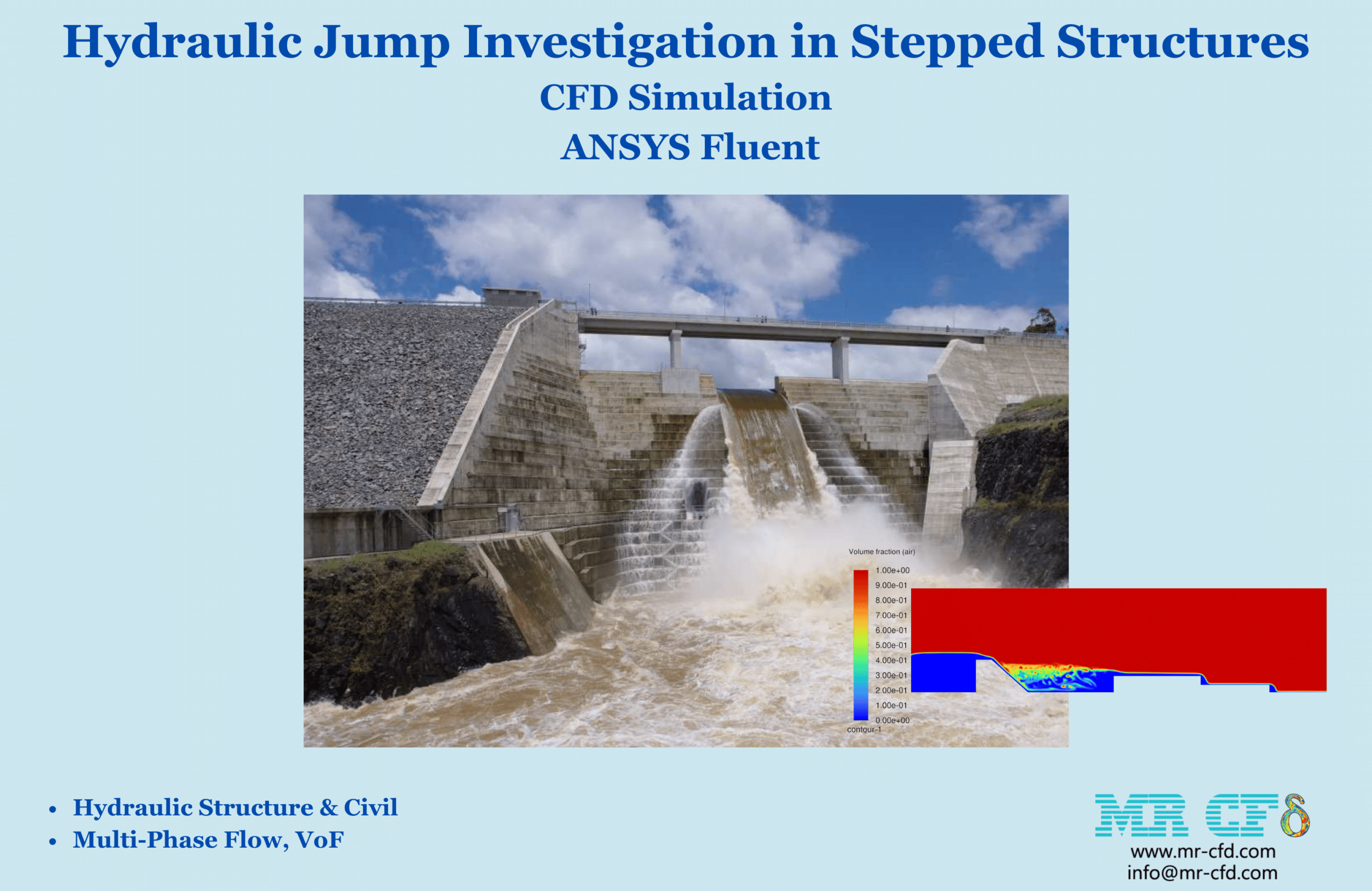
⦁ This problem simulates Hydraulic Jump Investigation in Stepped Structures, using Ansys Fluent software.
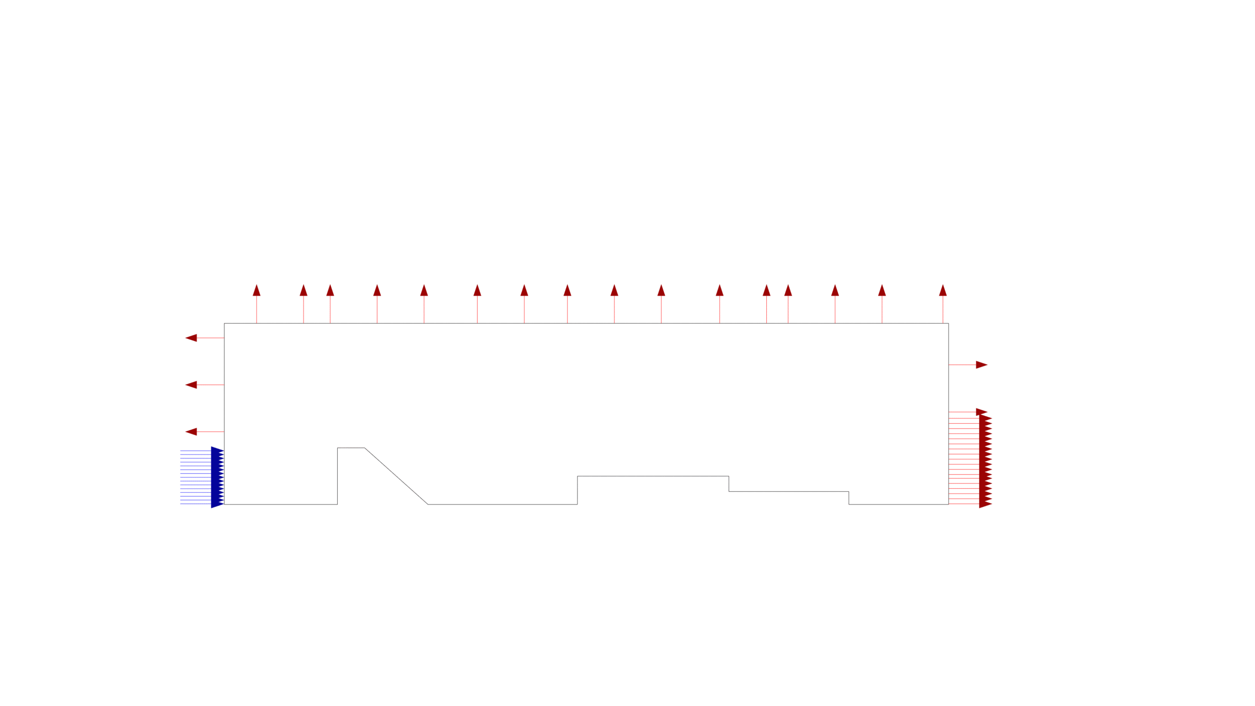
⦁ The 2-D geometry is designed in Design Modeler software.
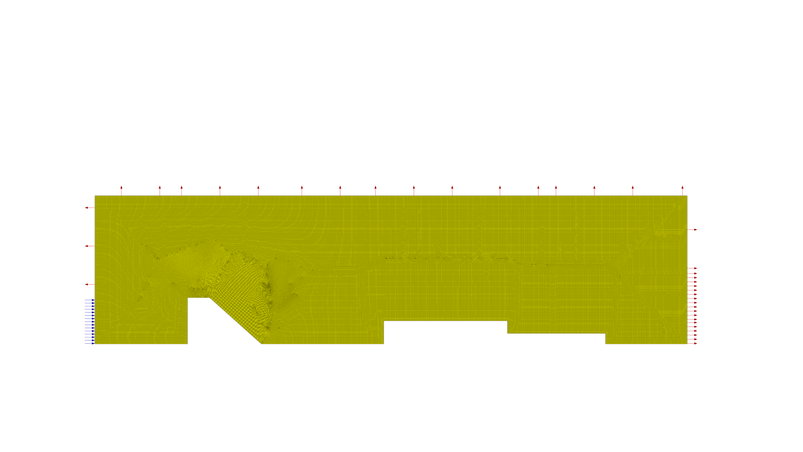
⦁ ANSYS Meshing software is used to generate the mesh; the element number equals 76,048.
⦁ In this project, the Formation of hydraulic jump is simulated using the VoF model.
⦁ Flow energy loss in this project is well modeled.
To Order Your Project or benefit from a CFD consultation, contact our experts via email ([email protected]), online support tab, or WhatsApp at +44 7443 197273.
There are some Free Products to check our service quality.
If you want the training video in another language instead of English, ask it via [email protected] after you buy the product.
Description
Hydraulic Jump Investigation for the flow descends from a weir to stepped structures CFD Simulation, ANSYS Fluent
Description
One of the trickiest phenomena in hydraulic engineering is the hydraulic jump. The current understanding of the phenomenon is far from complete due to its chaotic nature, which involves significant turbulence, severe air entrainment, and significant fluctuations in the pressure and velocity fields. Despite its complexity, the hydraulic jump’s turbulent nature is quite interesting for energy dissipation in several hydraulic works. Specifically, in large dams, stilling basins are the chosen energy dissipation structure. Such constructions use a hydraulic leap to release the surplus energy of the flow, ensuring that the discharge into the river occurs under the right circumstances. A weir is a barrier that requires water to flow over it in an open channel or river. Weirs are used to increase the water level and measure the head over the weir crest and weir geometry to determine flow rates. Ogee crest, sharp crested, and broad-crested weirs are the three primary varieties of weirs. Broad-crested weirs are inexpensive and have a straightforward design. Compared to other designs, such weirs are more frequently utilized for channel flow measurements. In this project, the flow coming down from an Ogee crest weir, the hydraulic jump that forms behind the stepped structures, and the passage of the flow over the stepped structures are investigated and analyzed with the help of computational fluid dynamics (CFD).
Ansys Fluent software provides the VoF model, which is a homogeneous model, for two or multi-phase flows where all phases are continuous and have a defined interface. The main goal of this model is to find this specific interface. The VOF model uses a special discretization to discretize the volume fraction equation, which makes the interface between the phases well modeled. To use this model, it must be observed that the mesh size is very small in the places where we have an interface.
In this 2D simulation, an inlet of 1.2 meters and an outlet of 2 meters are considered for water from the lower level. The inlet water flow speed is considered to be 0.5 m/s. The entire upper surface and the side surfaces that are not water inlets and outlets are considered air outlets. The length of the weir image on the lower surface is considered to be 2 meters. The length of the stepped structures is 3.345, 2.65 and 2.204 meters, respectively. In this project, the flow of water over the structures and the creation of a hydraulic jump have been well modeled.
CFD simulation methodology
In this project, the geometry is generated in Design Modeler With a position to enter the water and meshed in ANSYS Meshing with 76,048 elements. For simulation, VOF multiphase flow model has been used. The project is simulated in two phase and the phases are air and water. For the initial conditions of the simulation, water is considered in the area behind the weir and air in the rest of the domain. It should be noted that the simulation is done transiently. To capture the turbulent structures in this flow, realizable k-epsilon model has been used, taking advantage of the near-wall treatment of the scalable wall function.
Conclusion
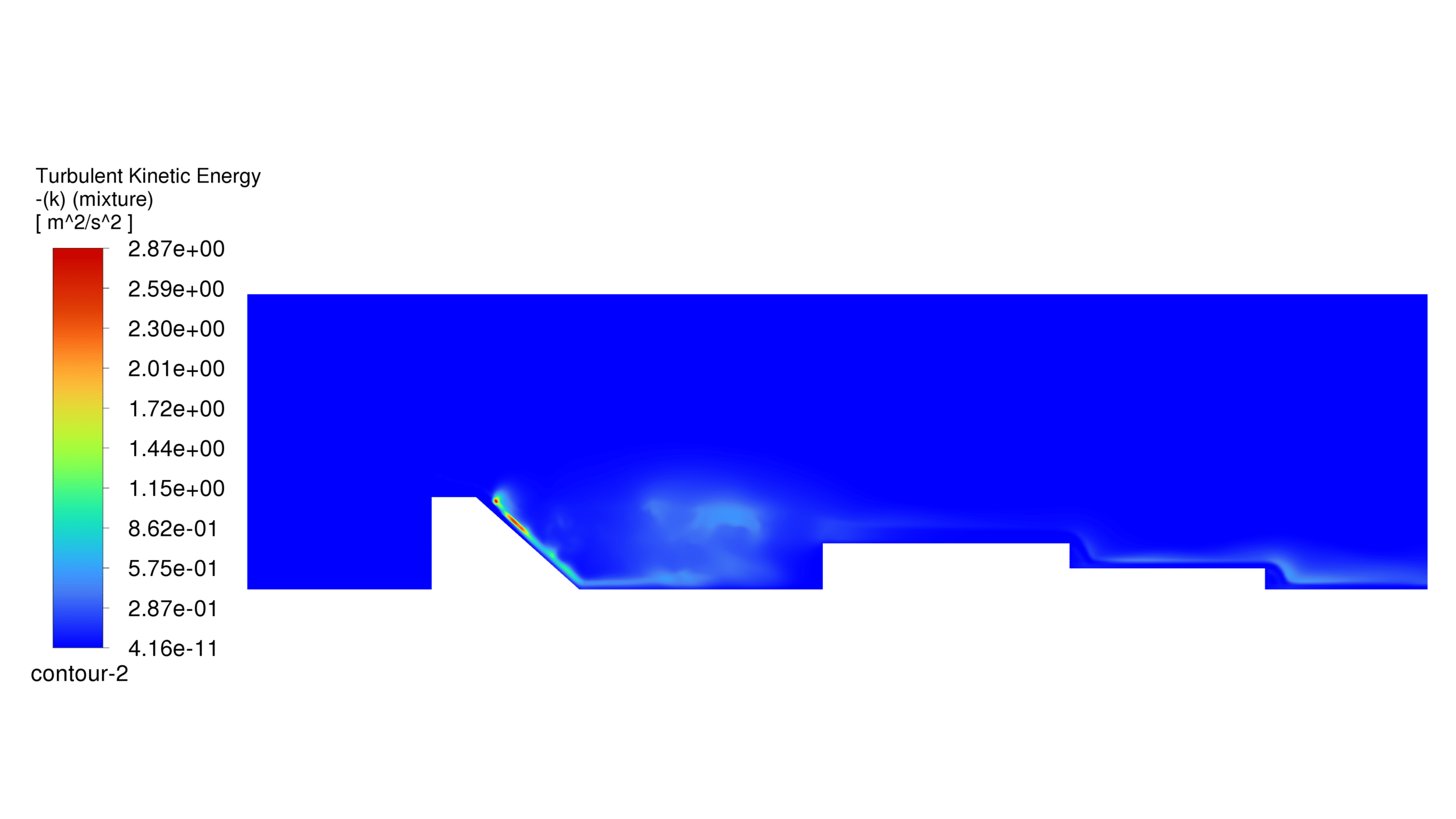
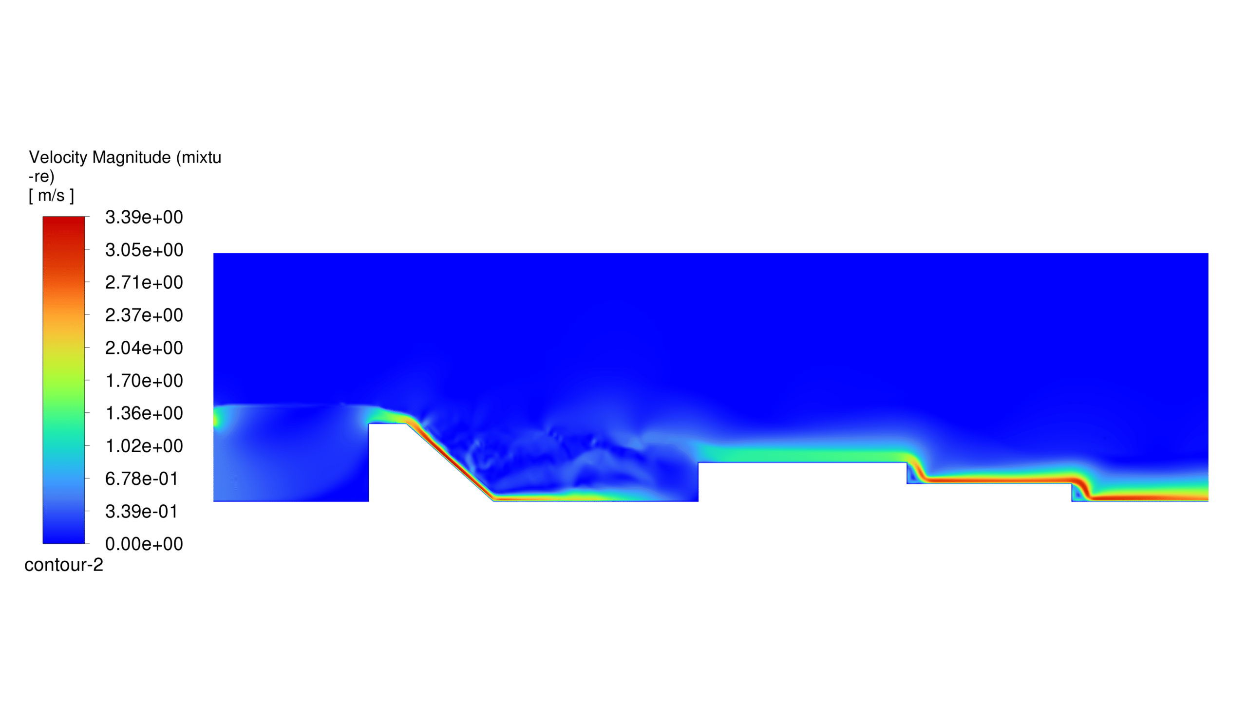
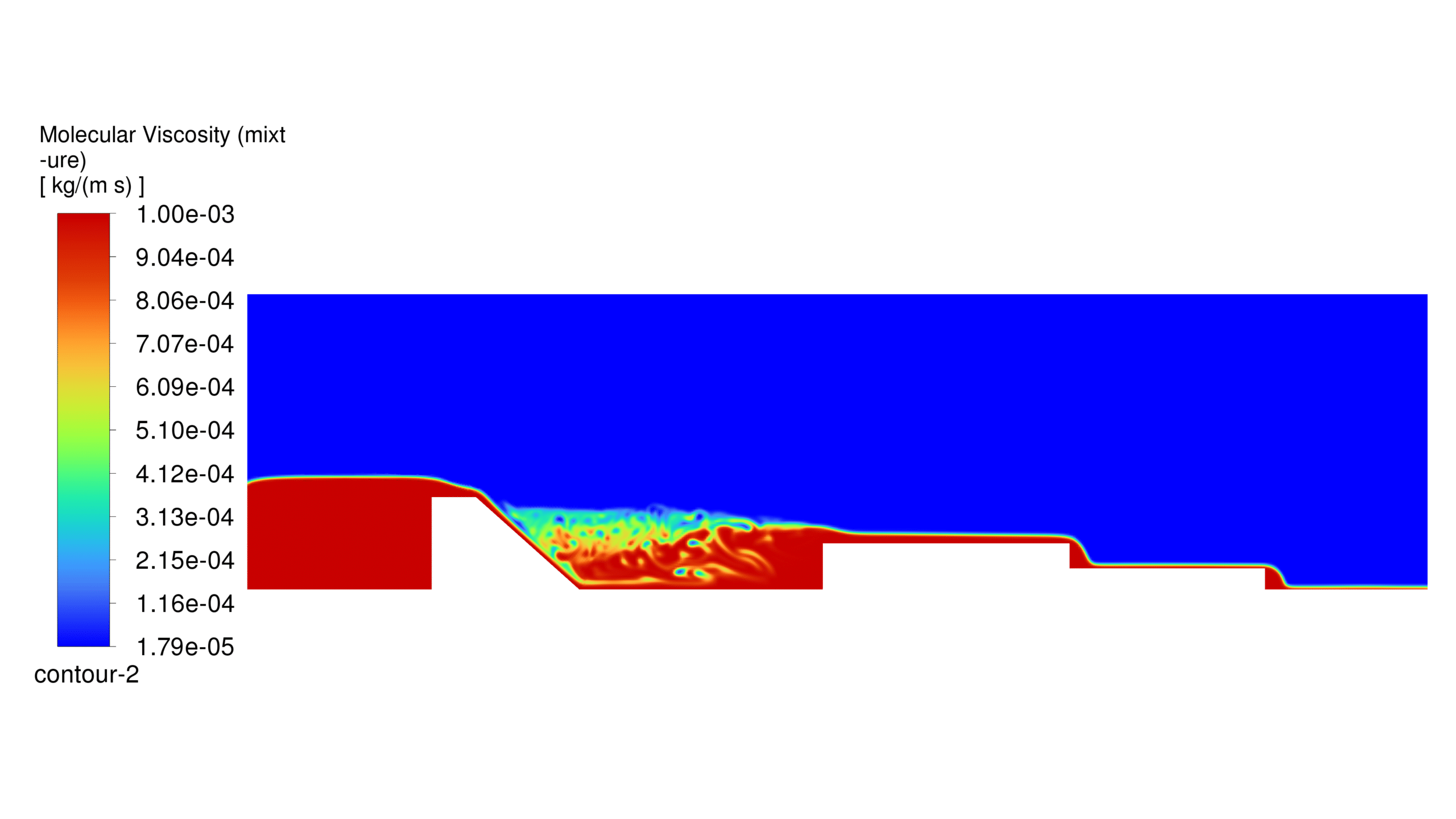
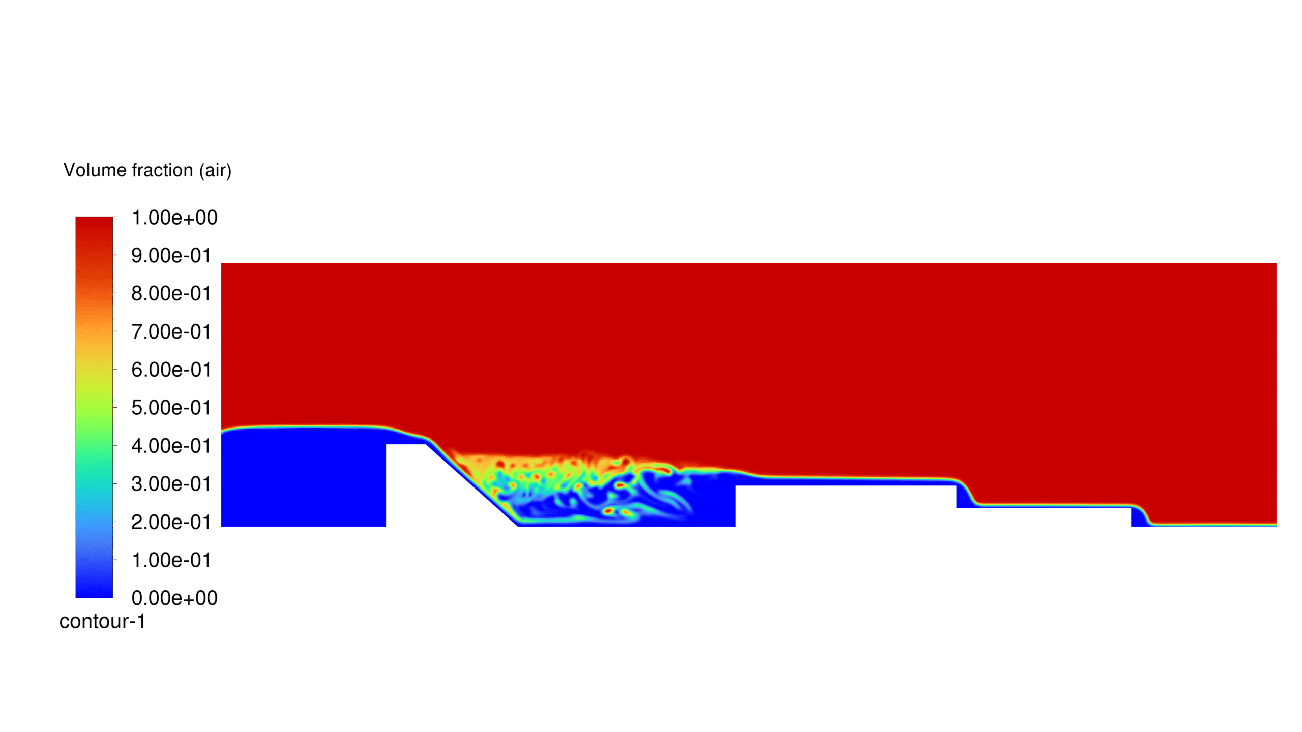
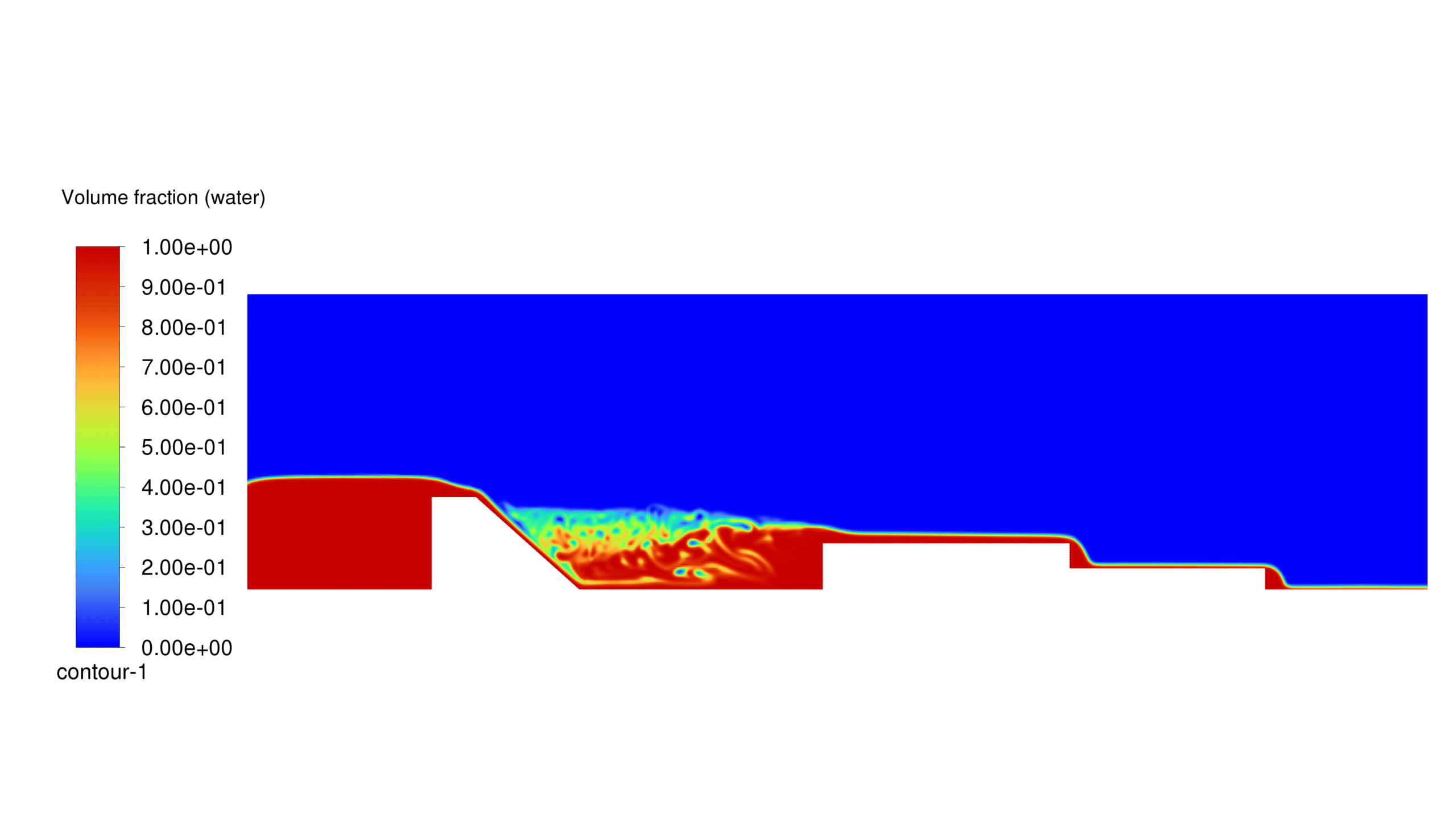
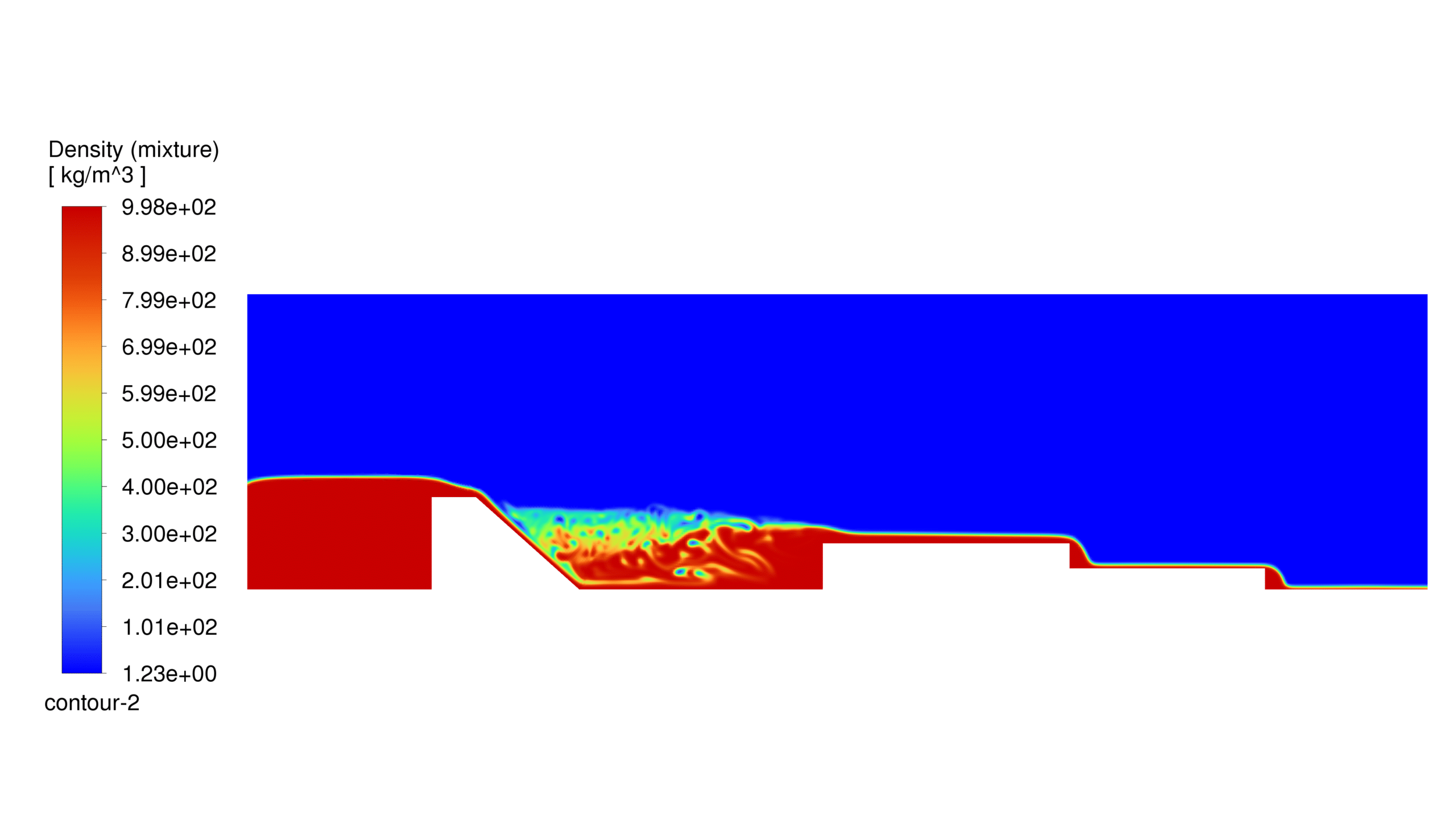
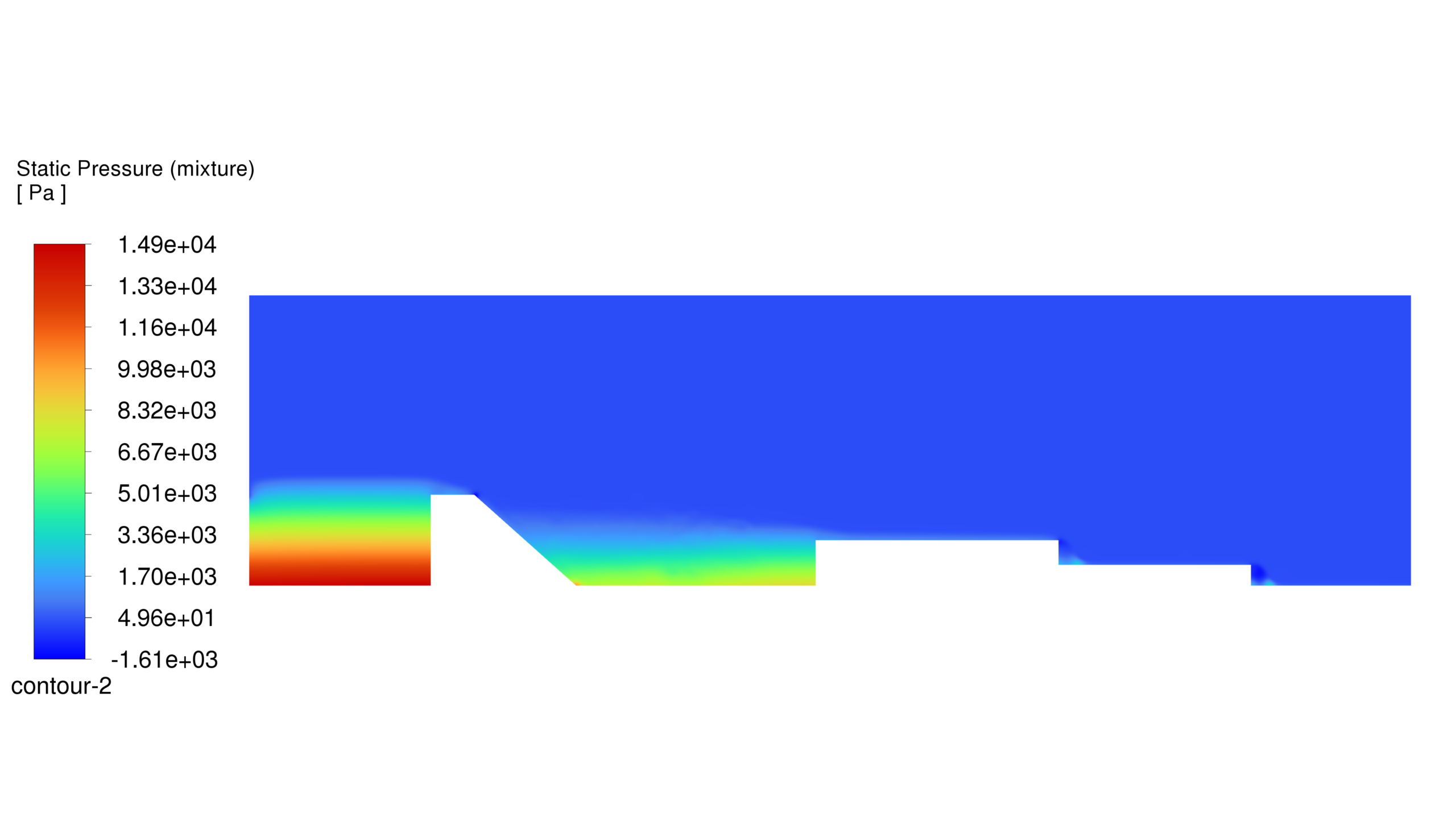
At the end of the solution process, two-dimensional contours related to pressure, velocity, viscosity, density, water volume fraction, air volume fraction and Turbulent Kinetic Energy (k) were obtained. Then the computational area is divided into 6 sub-areas and the velocity of the mixed flow is calculated in each one. This parameter can be considered as a measure of kinetic energy in each sub-region, which can clearly be seen the loss of kinetic energy in the areas of hydraulic jump formation. These flow velocity values are listed in the Table 1 and are also shown in Figure 1 for better understanding. Finally, an animation of the flow of water and the hydraulic jump formed behind the stepped structures has been prepared.


Reviews
There are no reviews yet.