Oscillatory Wave and its Effect on Fin Motion, ANSYS Fluent CFD Training
$220.00 Student Discount
- The problem numerically simulates the Rotational Motion of a Fin under the influence of Oscillatory Wave flow using ANSYS Fluent software.
- We design the 2-D model by the Design Modeler software.
- We Mesh the model by ANSYS Meshing software, and the element number equals 120049.
- We perform this simulation as unsteady (Transient).
- We use the two-phase VOF model to define the flow field containing the water and air.
- We use Dynamics Mesh to define deformation of the grid around the moving wall.
- We determine only one degree of freedom (1-DOF) to rotate the fin.
- We use a UDF to define the reciprocating motion of the wall that causes the wavy flow.
To Order Your Project or benefit from a CFD consultation, contact our experts via email ([email protected]), online support tab, or WhatsApp at +44 7443 197273.
There are some Free Products to check our service quality.
If you want the training video in another language instead of English, ask it via [email protected] after you buy the product.
Description
Description
The present problem simulates the rotational motion of a fin in a two-phase flow field under the influence of the generated Oscillatory Wave flow using ANSYS Fluent software. We perform this CFD project and investigate it by CFD analysis.
We design the 2-D geometry of the present model by Design Modeler software. The model’s geometry is divided into three main areas: structured, unstructured, and stationery.
We carry out the meshing of the present model using ANSYS Meshing software. The element number is equal to 120049. The unstructured mesh is used in the special region created around the blade because it is deformed and subject to a dynamic mesh process.
Therefore, this area must be capable of high flexibility against mesh change (remeshing) while the mesh is structured in other areas of the model.
The present model is unsteady because the model is concerned with simulating the rotational motion of a fin under the influence of a fluid oscillating wave that completely depends on time.
Also, the effect of gravity on the flowing fluid has been taken into account and equals 9.81 m/s2 along the y-axis of the present model because the gravitational force will affect the applied torque exerted on the fin completely.
Oscillatory Wave Methodology
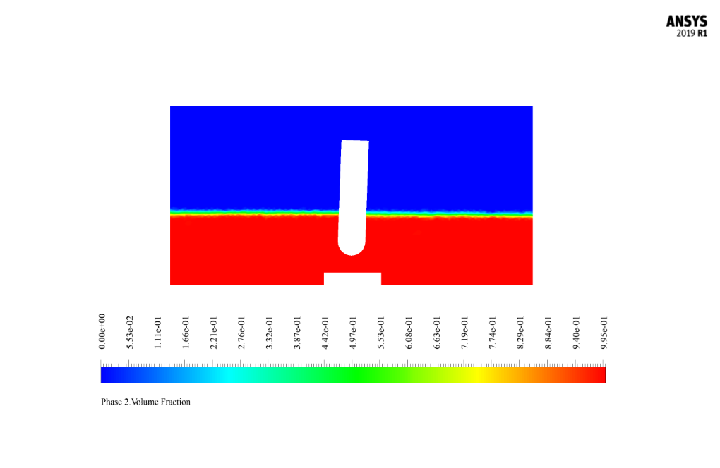
The two-phase flow in this problem is defined by the VOF model and consists of two phases: air as the primary phase and water as the secondary phase, with no interaction or mass transfer between the two phases.
The mixture of air and water flow within the main domain, and the movement of the rigid wall and the walls attached to that moving boundary create a wave of oscillation in the water flow.
This oscillatory wave produced by the flow applies compressive force and shear stress on the fin attached to the floor of the domain. As a result, the water forces acting on the fin cause it to rotate around its vertical axis as a rigid object.
Due to the nature of the problem requiring displacement at the model boundaries, a dynamic mesh technique was used to define the fluid flow.
Also, a UDF (user-defined function) defines the reciprocating motion of the scaffold wall that causes the waveform within the domain. The simulation was performed for 100 seconds, and the time step size was 0.001s.
In the present model, we use the dynamic mesh smoothing method, with a constant coefficient of spring equal to 0.7, the number of iterations equal to 500, and the convergence tolerance criterion of 0.001. We apply the remeshing method and local cell type. The current model does not use the spring mode.
The present model only has one degree of freedom (1-DOF) to rotate around the z-axis and the point of the fin’s rotation, which appears in a reciprocal motion around the center of its rotation due to the collision fluid wave.
In the present model, the moment of inertia applied to the fin is 0.1147 kg.m2, which is equivalent to the moment of inertia applied to the rotary rod around the endpoint of the rod (I = 1 / 3mL2).
Oscillatory Wave Conclusion
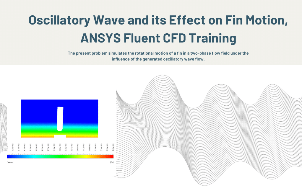
After the solution process, we obtained two-dimensional contours related to pressure, velocity, the volume fraction of liquid and air, and pathlines at t=2s.
Also, by enabling the write motion history option in the six DOF definition section, the fin location in the x and y coordinates and its angular placement at different times are stored as a data set in a text file. The data graph shows the angular changes of the fin position over time in 22.5 seconds.


Kimberly Terry –
What is the main objective of this Oscillatory Wave and its Effect on Fin Motion CFD Simulation?
MR CFD Support –
This simulation aims to analyze the effect of an oscillatory wave on the motion of a fin. It is particularly useful in studying the behavior of marine structures and devices.
Oren Champlin –
How accurate is this simulation?
MR CFD Support –
Our simulations are based on well-established physical principles and mathematical models. We also validate our results against experimental data to ensure accuracy.
Prof. Krista Roberts I –
Could you kindly elaborate on how the dynamic mesh technique was integrated with the UDF to create the oscillatory wave flow condition in the simulation?
MR CFD Support –
Absolutely, the dynamic mesh technique was used alongside a UDF to precisely simulate the oscillating wave. The UDF dictated the reciprocating movement of the boundary wall which in turn generated the oscillatory flow. As the boundary wall moved, the dynamic mesh adapted the grid in the fluid domain to accommodate the changes, ensuring accurate representation of the flow at any given time step.
Rae Kozey –
The training material is impressive! How does the VOF model enable the simulation of the interaction between the air and water phases without considering their mass transfer?
MR CFD Support –
The VOF (Volume of Fluid) model is designed to handle two or more immiscible fluids by tracking the volume fraction of each of the fluids throughout the domain. In this simulation, it captures the interface between the air and water without allowing for mass transfer because it treats the two fluids as separate yet interacting entities. Mass transfer is not considered in this model because the main focus is on the hydrodynamic effects of waves on the fin, which doesn’t necessarily involve the intermingling of the two fluids at a molecular level.
Reid O’Connell –
I am amazed by how realistic the simulation results appear. Great attention to detail in replicability of natural phenomena!
MR CFD Support –
Thank you for your positive feedback! We strive to create realistic simulations to provide valuable insights and we’re happy to hear you appreciated the details in the Oscillatory Wave and Fin Motion analysis.
Prof. Griffin Hahn –
How does the simulation model the effect of the wave on the fin motion?
MR CFD Support –
The simulation uses the dynamic mesh method to model the motion of the fin in response to the oscillatory wave.
Austin Fahey –
How does the simulation model the oscillatory wave?
MR CFD Support –
The oscillatory wave is modeled using the Volume of Fluid (VOF) method in ANSYS Fluent, which can simulate the interface between two or more immiscible fluids.
Mitchel Ziemann –
I am really impressed with how the effects of the oscillatory wave on fin motion were simulated. The details on the applied methodologies like using the dynamic mesh technique and the VOF model for the two-phase flow simulation clearly demonstrate the sophistication of the approach. Excellent work!
MR CFD Support –
Thank you so much for your kind review! We are delighted to hear that you were impressed with the detailed methodologies applied in the ‘Oscillatory Wave and its Effect on Fin Motion’ simulation. It’s always our goal to provide comprehensive educational experiences through our training materials. Your acknowledgment of the complexity and sophistication of our approach is deeply appreciated. If you have any further questions or need assistance with our products, please feel free to reach out. Once again, thank you for your feedback!
Angeline Bednar –
I would like to know more about how the rotational movement of the fin is captured in the simulation. Does the UDF fully define the motion, or are there additional constraints on the fin’s movement?
MR CFD Support –
The rotational movement of the fin is primarily driven by the user-defined function (UDF) which accurately specifies the reciprocating motion of the scaffold wall. However, the fin itself is also set to have one degree of freedom (1-DOF) to rotate around its z-axis at a specific point. This combined approach – the defined UDF motion and this set DOF – allows the fin to exhibit the rotational behavior as intended by the simulation design. There aren’t additional constraints on the fin’s movement beyond this specification; it freely rotates in response to the oscillatory wave forces.
Dr. Joana Osinski MD –
The project summary mentions a UDF for reciprocating motion. Is this UDF included in your training materials, or do I need to write it myself?
MR CFD Support –
The UDF (user-defined function) required for reciprocating motion is indeed part of the training materials. It ensures that you can replicate the oscillatory wave motion exactly as in this project and understand how such functions are implemented and used within ANSYS Fluent simulations.