Water Turbine (Horizontal Axis), ANSYS Fluent CFD Simulation Training
$160.00 Student Discount
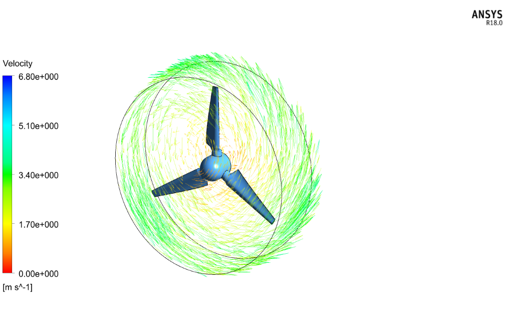
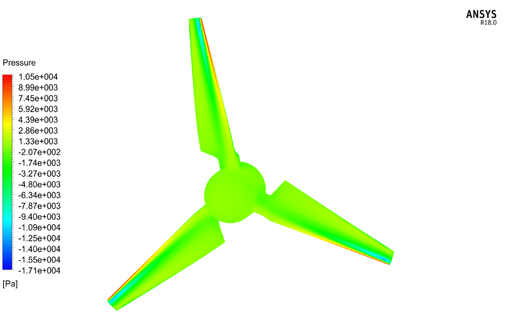
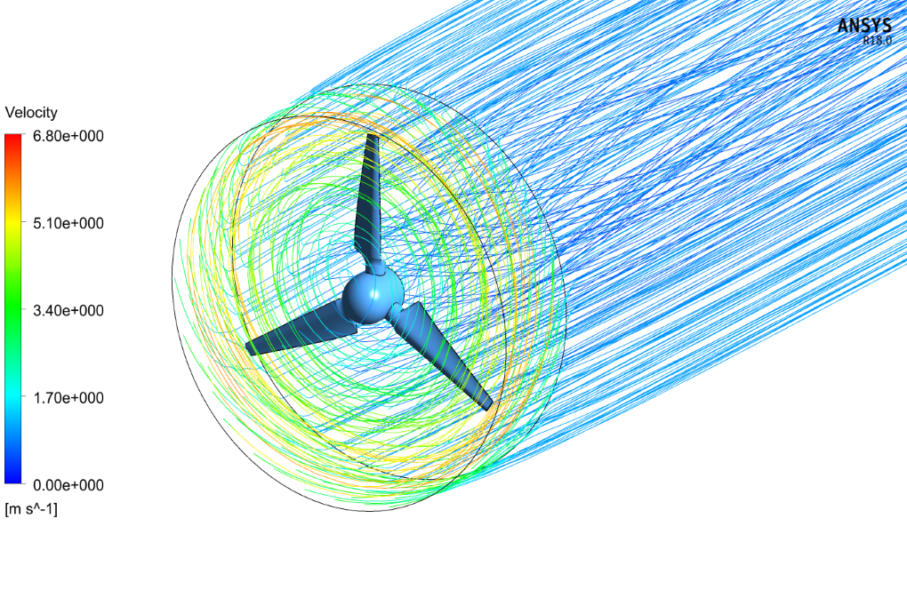
The present study investigates the water flow on the horizontal axis water turbine blades so that the purpose of the problem is to investigate the distribution of velocity and pressure on the blade’s wall.
Click on Add To Cart and obtain the Geometry file, Mesh file, and a Comprehensive ANSYS Fluent Training Video.
To Order Your Project or benefit from a CFD consultation, contact our experts via email ([email protected]), online support tab, or WhatsApp at +44 7443 197273.
There are some Free Products to check our service quality.
If you want the training video in another language instead of English, ask it via [email protected] after you buy the product.
Description
Water Turbine Problem Description
The present study investigates the water flow on the horizontal axis water turbine (HAWT) blades so that the purpose of the problem is to investigate the distribution of velocity and pressure on the wall of the blade by ANSYS Fluent software. There are two areas around the blades, including a cylindrical area just around the blades and a large area around the cylinder. The flow of water in the large outer space behaves as a normal flow, while in the cylindrical region around the blades, the rotational flow is caused by the rotational motion of the blades.
CFD Assumption
To simulate the present problem, several assumptions are considered:
The simulation is Steady State. Because the present turbine is of horizontal axis type and therefore time will not affect drag and lift forces.
The solver is Pressure-Based.
The Gravity Force is ignored.
Geometry and Mesh of the Water Turbine
The present model is designed in 3-D form so that the section of the turbine blades is a S814-type airfoil whose coordinates are obtained from the Airfoil Tools website and output in the form of a notepad file. Since the airfoil cross section of the blades decreases or increases with different scales at a given scale, excel is used to define the coordinates of the blades at different points. Each airfoil section is then plotted in SOLIDWORKS software at appropriate angles and coordinates and then inserted into the Design Modeler software to design the blades and axis of the turbine. In the Design Modeler software, we create a rotational water flow around the turbine blades and a large space designed as a normal water flow space.
An Unstructured mesh was performed using ANSYS Meshing software. To increase the accuracy of the modeling, the boundary layer mesh on the surfaces of the turbine blades was used and the number of cells produced was 4270222.
Water Turbine CFD Simulation
Here is a summary of the steps in the table to define and solve the problem:
| Models | |||
| k-omega | Viscous model | ||
| SST | k-omega model | ||
| Boundry conditions | |||
| Velocity inlet | Inlet type | ||
| 1 m.s-1 | velocity | ||
| Pressure outlet | Outlet type | ||
| 0 Pa | gauge pressure | ||
| wall | Walls type | ||
| stationary wall | all walls | ||
| Solution Methods (water turbine) | |||
| Simple | Pressure-velocity coupling | ||
| Second-order upwind | pressure | Spatial discretization | |
| Second-order upwind | momentum | ||
| Second-order upwind | turbulent kinetic energy | ||
| Second-order upwind | turbulent dissipation rate | ||
| Initialization (water turbine) | |||
| Standard | Initialization method | ||
| -1 m.s-1 | velocity (z) | ||
Frame Motion Method
The purpose of the present simulation is to investigate the effect of water flow on turbine blades. In this case, the turbine blades rotate at a rotational speed of 191 rpm and the water in the area surrounding the blades is stationary. Using the above method, the blades can be assumed to be constant and the flow of water around the blades is assumed to be a rotating zone with the same rotational speed of 191 rpm around the Z axis. Also, since the simulation is Steady State, the Mesh Motion option is disabled because it is used when the time effect must be applied to the problem solving and the purpose of the problem is to define the rotational speed for the blade.




Maybelle Stracke –
How can this simulation help in the CFD course project that I have taken in university this term?
MR CFD Support –
This simulation can provide valuable insights into the performance of a 3-blade horizontal axis water turbine, helping you optimize its design and operation for maximum efficiency.
Olen D’Amore –
Hi, it was good training, the teacher is clear in his expression, good vital points are also said.
Alessandra Conn –
I am working on using mesh motion, can preparing this project help me?
MR CFD Support –
Yes, you can do your project according to the tips mentioned. Although, this simulation applies a Steady-State solver while using the Mesh Motion Method needs a Transient solver. But the CFD simulation procedure is the same in more than 90% of the content.
Ernest Schroeder –
How does the simulation model the interaction between the water and the turbine blades?
MR CFD Support –
The simulation models the interaction between the water and the turbine blades using the sliding mesh model in ANSYS Fluent, which allows for accurate prediction of the fluid-structure interaction.
Marilou Feest –
How is the power output of the turbine calculated in the simulation?
MR CFD Support –
The power output of the turbine is calculated based on the torque exerted on the turbine blades and the rotational speed of the turbine.
Gabriel D’Amore –
Can you customize this simulation to fit my specific needs?
MR CFD Support –
Yes, at MR-CFD, we are open to contributions and can accommodate your desired simulations. Please feel free to reach out to us with your specific requirements.
Prof. Sid Bashirian DDS –
The description definitely highlights intricate modeling and analysis! Can I know more about how turbulence is considered in the simulation since you’re using the k-omega SST model?
MR CFD Support –
In this simulation, turbulence is represented via the Shear-Stress Transport (SST) k-omega model. This model combines both the standard k-omega model at the near-wall regions for more accurate boundary layer predictions and switches to the k-epsilon model in the free stream to accurately capture the turbulence away from walls. Turbulent kinetic energy (k) and specific rate of dissipation (omega) are calculated at every iteration to ensure the behavior of the water flow around the HAWT blades is well predicted by the CFD simulation.
Albin Reilly DDS –
The CFD training was immensely helpful! I could understand the complexity behind the simulation of water flow over turbine blades, and how rotational speeds influence performance. The detailed settings for boundary conditions, solving methods, and turbulence models were particularly useful for learning how to set up my own simulations for similar applications.
MR CFD Support –
Thank you for your positive feedback! We’re thrilled to hear that you found our CFD simulation training so informative and that it helped you understand the water turbine simulation in depth. If you ever need further assistance or have more questions, do not hesitate to contact us!
Sydnie Abbott –
I thoroughly enjoyed the clean presentation and detailed steps for the Water Turbine CFD Simulation Training. It really feels like such complex information was made accessible and I gained valuable insights into the effects of water flow on turbine blades. Great work!
MR CFD Support –
Thank you very much for taking the time to leave us a review! We are delighted to hear that our training on Water Turbine CFD Simulation using ANSYS Fluent provided you with valuable insights and clarity on the subject. We strive to present complex concepts in an accessible manner, so we’re thrilled that it resonated with you. Stay tuned for more educational content!
Katharina Becker –
The training was superb! The explanation of water kinetic energy capture using the HAWT and the detailed setup of the simulation including meshing, boundary conditions, and solver setup were very easy to follow.
MR CFD Support –
We’re thrilled to hear our training on the Water Turbine (Horizontal Axis) CFD Simulation met your expectations and provided you with a clear understanding of the entire process. Thank you for your positive feedback!
Janessa Hirthe –
I’ve gone through the CFD simulation of the HAWT in ANSYS Fluent, and it’s truly impressive! The details on the airfoil design and adaptive mesh refinements ensure that the results are very accurate. Particularly, the application of the SST k-omega model certainly provides a clear insight into turbulence effects on the blades. Outstanding work!
MR CFD Support –
Thank you for your kind words! We are delighted to hear that you find our simulation and analysis impressive. It’s great to see that you understand the importance of an accurate airfoil design and appreciate the complexities of the SST k-omega turbulence model in predicting the performance of water turbine blades. Your satisfaction with our CFD simulation training reinforces our commitment to high-quality educational content. If you have any more feedback or need further assistance, please let us know.
Efrain Cassin V –
The training content is very detailed and walks you through step by step. The inclusion of a frame motion method is particularly impressive. I successfully replicated the results using your guidance, which helped me get a solid understanding of the interaction between water flow and turbine blades.
MR CFD Support –
Thank you for your positive feedback! We’re delighted to hear that our training was helpful and clear, allowing you to simulate the water turbine accurately. It’s great to know that the detailed steps and the frame motion method provided you with a solid understanding of the CFD application. If you have any further questions or need more guidance on similar projects, feel free to reach out to us.
Prof. Shane Brekke I –
I’m truly fascinated by the process described for this water turbine simulation. It’s amazing to see how modern tools like ANSYS Fluent can model complex fluid dynamics. Great job illustrating the transition from airfoil data coordination using Excel to blade modeling in SOLIDWORKS, followed by the final stage of it all being brought together in the Design Modeler. This has provided a profound insight into the practical application of CFD in optimizing turbine blade designs for energy efficiency.
MR CFD Support –
Thank you for taking the time to share your positive experience with our Water Turbine CFD Simulation Training. We are thrilled to hear that you found the transition from initial data processing to the final modeling in ANSYS Fluent to be a highlight. Ensuring that complex fluid dynamics are accessible and comprehendible is a goal for us, and your appreciation motivates us to continue in this mission. If you’re interested in further studies or have any other questions, please feel free to reach out. Thank you for your review!
Mikel Howe Jr. –
I am thoroughly impressed with how the simulation managed to capture the effects of water on the HAWT blades! The detailed setup really shows in the quality of the results produced. Can the simulations be adapted to test variances in blade design, or is it specific to the S814-type airfoil shape?
MR CFD Support –
Thank you for your kind words! Yes, the simulation setup can be adapted to test different blade designs and airfoil shapes. By altering the geometry in the initial model and executing the CFD process likewise, you can analyze how various designs influence the turbine’s performance. The modifications include adjusting the airfoil coordinates and scales, corresponding to a new design in the simulation process.
Jermaine Runolfsson –
Fantastic learning tool! The detailed setup for the water turbine CFD simulation provided a clear insight into the computational fluid dynamics involved. I’m impressed with the intricacies of designing the geometry and the precision in meshing for accurate results. The step-by-step breakdown in setting up the problem, the selection of turbulence models, boundary conditions, as well as the simulation type made it particularly useful for understanding the dynamics of horizontal axis water turbines.
MR CFD Support –
We’re thrilled to hear that you found our Water Turbine CFD Simulation training module to be so valuable! Your feedback is much appreciated. It’s great to know that the details provided clear insight and helped you understand the fluid dynamics of water turbines effectively. Thank you for taking the time to recognize the effort put into ensuring precision in the setup and for your kind words. Keep an eye out for more useful training modules!
Dr. Gussie Heaney I –
I was truly impressed by the clarity provided in the simulation on the distribution of velocity and pressure on the blade surfaces and the intricate details that were accommodated in the mesh to facilitate precise computations. The choice of the k-omega SST model seems optimal for capturing the turbulent flow characteristic of HAWT blade applications.
MR CFD Support –
Thank you for your positive feedback on our Water Turbine simulation training. We are delighted to hear that you found the simulation to be clear and informative, and appreciate your acknowledgement of the meshing details and our turbulence model choice. Your satisfaction with the precision of our computational study is of great importance to us. If you have any further insights after applying this simulation to your projects, please feel free to share!
Prof. Ayla Mertz –
I am impressed by the detailed approach and high accuracy of meshing in the water turbine simulation. It is evident that great care was taken in modeling the challenging aspects of the rotating blades and the airfoil cross-sections. The use of the SST k-omega model seems particularly well-suited for capturing the flow characteristics in this scenario. Well done on executing such a complex simulation with precision!
MR CFD Support –
Thank you for your positive feedback. We appreciate your recognition of the meticulousness and accuracy we put into our CFD simulations using ANSYS Fluent. It’s great to hear that the effort we invested in the meshing and choice of the SST k-omega model has resulted in a level of detail and precision that did not go unnoticed. Your kind words are very encouraging for our team! If you ever have any questions or need more insight into our simulation processes, please do not hesitate to ask.
Ashlynn Thiel –
I used the product for my project, and I was blown away by the attention to detail in modeling water flow around turbine blades. The results helped me understand pressure distribution effectively.
MR CFD Support –
Thank you so much for sharing your feedback! We are thrilled to hear that our training on the water turbine CFD simulation in ANSYS Fluent was instrumental for your project and helped you achieve a deeper understanding of the pressure distribution phenomena. If you have any more insights or projects you’d like to explore, don’t hesitate to reach out.