Manometer of Venturimeter CFD Simulation by Ansys Fluent, Training
$80.00 Student Discount
In this project, a monometer has been simulated, and the results of this simulation have been investigated.
Click on Add To Cart and obtain the Geometry file, Mesh file, and a Comprehensive ANSYS Fluent Training Video.To Order Your Project or benefit from a CFD consultation, contact our experts via email ([email protected]), online support tab, or WhatsApp at +44 7443 197273.
There are some Free Products to check our service quality.
If you want the training video in another language instead of English, ask it via [email protected] after you buy the product.
Description
Description
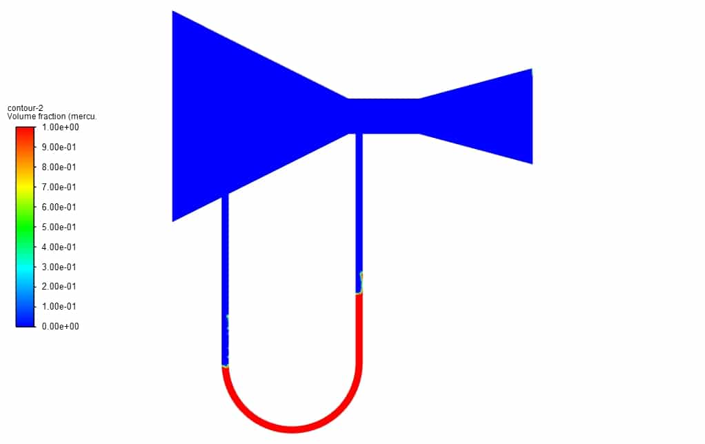
In this project, we study a Manometer of Venturimeter CFD Simulation by Ansys Fluent, and it has been shown how there is variation in U-tube manometric fluid column. The multiphase VOF model has been used. A convergent and divergent nozzle has been used to create a pressure difference. One end of the manometer is attached at the throat, and the other at the converging section. There is a rise in the liquid column in the U- tube manometer at the low-pressure region.
Monometer of Venturimeter CFD Simulation by Ansys Fluent
Venturimeters are pressure measurement devices that are commonly used in everyday life. For example, pressures in piping systems are constantly monitored using these devices. The U-tube manometer is a special manometer that gets its name from its U-shaped tube. The straight portions of this U are commonly referred to as the manometer’s arms, limbs, or ends. The manometer is typically filled with a dense, colored fluid called the manometer fluid, which is used to visualize the pressure difference between the two ends of the tube. As the pressure at one of its ends increases, the manometer fluid inside the tube is pushed downward at that end.
This causes the manometer fluid to rise at the other end of the device. The difference in the fluid levels between the two ends is then used to measure the pressure difference. When used properly, the manometer, one of the earliest pressure-measuring instruments, is very accurate. The manometer has no moving parts subject to wear, age, or fatigue. Manometers operate on the Hydrostatic Balance Principle: a liquid column of known height will exert a known pressure when the weight per unit volume of the liquid is known.
Geometry & Mesh
The 2-D geometry of the present model is generated using Design Modeler software.
The meshing of the present model has been done using Ansys Meshing software. The mesh type is unstructured in all of the computational domains, and the element number is equal to 42,413.
CFD Simulation
To simulate the present model, we consider several assumptions:
- The solver is pressure-based.
- The current simulation is unsteady in terms of time.
- The gravity effect is equivalent to -9.81 m.s-1.
Here is a summary of the steps for defining the problem and its solution in the following table:
|
Models
|
|||
|
Multiphase
|
|||
|
|
Homogeneous model | Volume of fluid | |
|
|
Number of Eulerian phases | 2(air& mercury) | |
|
|
Interface modeling | Sharp | |
|
|
Formulation | explicit | |
|
|
Body force formulation | Implicit body force | |
|
Viscous model
|
k-epsilon | ||
|
Material Properties
|
|||
|
Air
|
|||
|
|
Density | 1.225 | |
|
|
viscosity | 1.7894e-05 | |
|
mercury
|
|||
|
|
Density | 13529 | |
|
|
viscosity | 0.001523 | |
| Boundary conditions | |||
| Inlet air
|
Velocity inlet | ||
| volume fraction
|
1 | ||
|
|
velocity magnitude | 1.8 m.s-1 | |
| Outlet | Pressure outlet | ||
|
gauge pressure
|
0 Pascal |
||
|
|
air backflow volume fraction
|
0 |
|
| Solution Method | |||
|
Pressure-velocity coupling
|
Piso |
||
|
Spatial discretization
|
pressure |
presto |
|
|
momentum |
first-order upwind
|
||
|
|
Volume fraction
|
Geo reconstruct |
|
|
|
Turbulent kinetic energy |
First-order upwind |
|
|
|
Turbulent dissipation rate
|
First-order upwind |
|
| Initialization | |||
|
Initialization method
|
Standard |
||
|
Patch
|
Phase |
air |
|
|
|
Variable
|
Volume Fraction |
|
|
|
Registers to patch |
region_0 |
|
|
|
Value
|
0 |
|
| Run calculation | |||
| Time step size |
0.001 |
||
| Max iterations/time step |
10 |
||
|
Number of time steps |
1200 |
||
Monometer Results
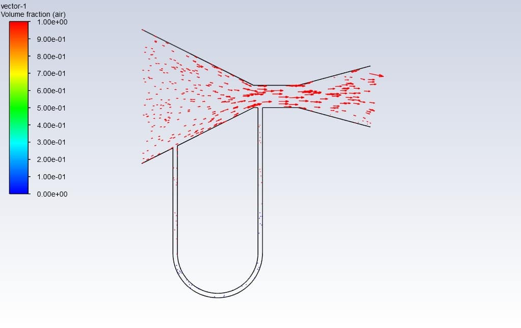
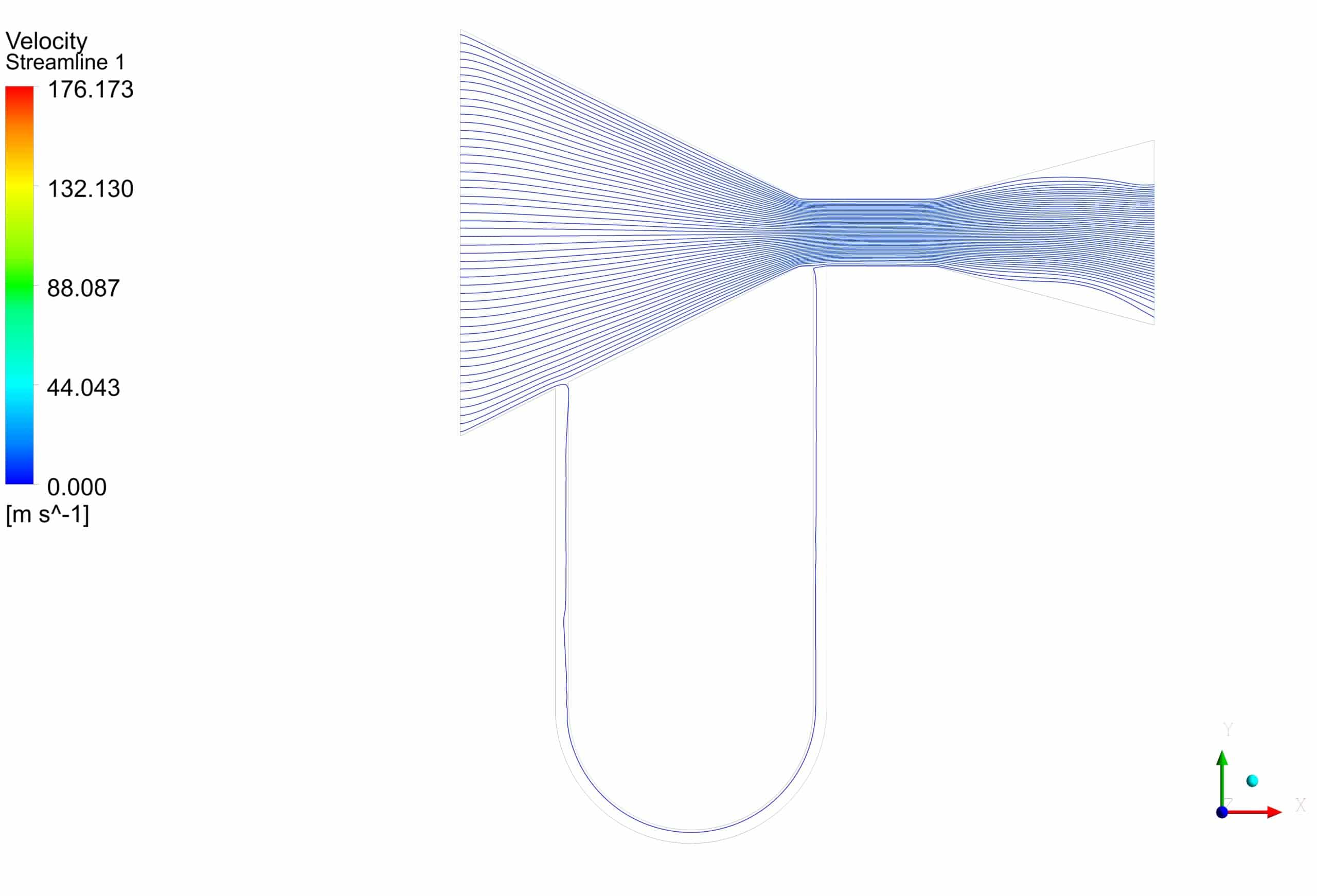
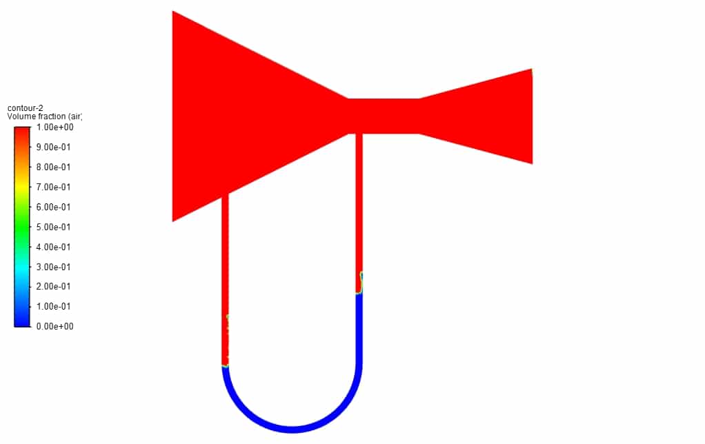
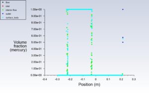
First, a volume fraction diagram was drawn in different positions in this simulation. Then two-dimensional contours related to density, streamline, air volume fraction and mercury volume fraction were obtained. The images show that Initially, the height of the liquid column is equal on both sides. But as the gas enters the manometer, the height of the mercury column changes.


Vada Beatty –
The training materials look quite comprehensive! After going through the simulation, I found the visuals for the liquid column movement particularly helpful in understanding the pressure changes within the Manometer setup.
MR CFD Support –
Thank you for your feedback! We are thrilled to hear that the simulation visuals were helpful for you to understand the concept of pressure changes in the Manometer. We strive to provide clear and instructive materials, and we’re glad it made a difference in your learning experience.
Calista Cruickshank –
Can you provide more insight on how the initial conditions of air and mercury volume fractions were set up for this simulation?
MR CFD Support –
In this simulation, the initial conditions for air and mercury volume fractions were set to represent the beginning state of the manometer. At the start, the mercury column is at the same level on both sides of the U-tube. Standard initialization was used with the patch method to specify that the region representing the manometer’s limb has 0 volume fraction for air, meaning it was fully occupied by mercury initially.
Hal Beahan –
The training on Monometer CFD Simulation was comprehensive and illuminating. The setup details were systematically explained, and understanding the application of the VOF model in Ansys Fluent within the context of a U-tube manometer made it easier to grasp the concept of pressure measurement in fluids. The step-by-step guide on setting up boundary conditions and initial parameters further aided in solidifying the knowledge. Excellent material for anyone looking to enhance their skill in computational fluid dynamics!
MR CFD Support –
Thank you for your positive feedback! We’re thrilled to hear that our training module on Monometer CFD Simulation using Ansys Fluent met your expectations and proved helpful. It’s always rewarding to know that our content is assisting customers in improving their CFD skills. If you have any more questions or need further assistance, feel free to reach out. Keep learning and happy simulating!
Donavon Mohr –
This training was illuminating! The level of detail provided in setting up the conditions for the U-tube monometer simulation really helps to understand the underlying principles of the mechanics involved. Seeing the progression of the mercury column as the pressure difference changes is fascinating!
MR CFD Support –
Thank you for your positive review! We’re thrilled to hear you found the monometer simulation details and the demonstration of principles through ANSYS Fluent enriching. Insights into fluid mechanics can indeed be fascinating, and we’re glad our training could illuminate this area for you. Should you have any questions or need further assistance in your learning journey, don’t hesitate to reach out!
Prof. Marilou Hoeger DDS –
I just completed the Monometer CFD Simulation by Ansys Fluent training, and I must say I’m quite impressed with how comprehensively it covered the U-tube manometric fluid column variation. The detailed geometry and precise meshing instructions facilitated a clear understanding of pressure calculations using a simple yet effective device. Following along with the simulation steps and observing the real-time changes in fluid volume fraction provided a hands-on learning experience that reinforced theoretical knowledge flawlessly.
MR CFD Support –
Thank you for your positive feedback! We’re delighted to hear that the training provided you with a thorough understanding and practical experience in managing the Monometer CFD Simulation. It’s fantastic to know that our approach to teaching complex fluid dynamics principles via hands-on simulation was effective for your learning. If you have any more questions or need further assistance, feel free to reach out!
Dr. Nayeli O’Kon III –
I enjoyed learning with the Monometer CFD Simulation training by Ansys Fluent. The clear step-by-step process and detailed assumptions made it easy to follow. The way the tutorial progresses from creating the geometry to running the calculations was practical and engaging.
MR CFD Support –
Thank you for your positive feedback! We’re delighted to know that our Monometer CFD Simulation training module helped you understand the process clearly and was engaging for you. Your satisfaction is our priority, and we’re pleased that we could provide an informative and enjoyable learning experience.