
Multi-Stage Axial Gas Turbine CFD Simulation
$180.00 Internship
- The problem numerically simulates a Multi-Stage Axial Gas Turbine using ANSYS Fluent software.
- We design the 3-D model with the ANSYS Blade Gen.
- The meshing of the present model has been generated by TurboGrid software and the total cell number is 12,182 elements.
- The compressor motion has been modeled with the MRF method.
- The Turbo Workflow module was used to model the turbine.
To Order Your Project or benefit from a CFD consultation, contact our experts via email (info@mr-cfd.com), online support tab, or WhatsApp at +44 7443 197273.
There are some Free Products to check our service quality.
If you want the training video in another language instead of English, ask it via info@mr-cfd.com after you buy the product.
Description
Multi-Stage Axial Gas Turbine Simulation, ANSYS Fluent CFD Training
Description
An axial turbine is a turbine in which the flow of the working fluid is parallel to the shaft, as opposed to radial turbines, where the fluid runs around a shaft, as in a watermill. An axial turbine has a similar construction as an axial compressor, but it operates in the reverse, converting the flow of the fluid into rotating mechanical energy.
A set of static guide vanes or nozzle vanes accelerates and adds swirl to the fluid and directs it to the next row of turbine blades mounted on a turbine rotor. Axial-flow turbines are the most widely employed turbines using a compressible fluid. The development of the steam turbine preceded the gas turbine by many years.
Thus, the axial-flow turbine used in gas turbines is an outgrowth of steam turbine technology. In recent years, the trend in high turbine inlet temperatures in gas turbines has required various cooling schemes. Axial-flow turbines are now designed with a high work factor to obtain lower fuel consumption and reduce the noise from the turbine.
There have been great strides in the cooling of turbine blades and vanes, from cooling with air and steam to the development of new blade structures. The new advanced gas turbine blades operating at very high temperatures are designed to eliminate both transverse and linear grain boundaries.
In this case, the compressor was modeled as 4 stages (2 rotors, 2 stators) with a 130 blade in each stage to observe a high-performance and high-pressure compressor in its working condition.
The present model in the 3-D domain of this simulation has been designed in ANSYS Blade Gen. The domain contains a mass flow inlet and pressure outlet.
The meshing of the present model has been generated by TurboGrid software. The mesh grid is unstructured; The total cell number is 12,182 elements.
Methodology: Multi-Stage Axial Gas Turbine CFD Simulation
In this simulation, the pressure-based solver has been used. For modeling turbulence, the k-omega SST model was used, which simulates the compressor at the operational point with a mass flow rate of 520 kg/s.
The compressor motion has been modeled with the MRF method, each stage rotates at the speed of 6000 rpm. Also, the Turbo Workflow module was used to model the turbine.
Conclusion
In the simulation results, according to the Mach number contour, it is clear how to flow speed changes through passages and increases in each stage, and according to the pressure counter, the pressure drops after each stage to give the system a P-ratio of 0.8.
The speed triangles created because of rotating rotors are visible and the pressure contour on the blades are showing that how the flow stagnated and also separated through the system. The efficiency of the system is calculated by using a software workflow scheme and resulted in a value of 18% for the turbine.
You must be logged in to post a review.
Related products
-
Sale

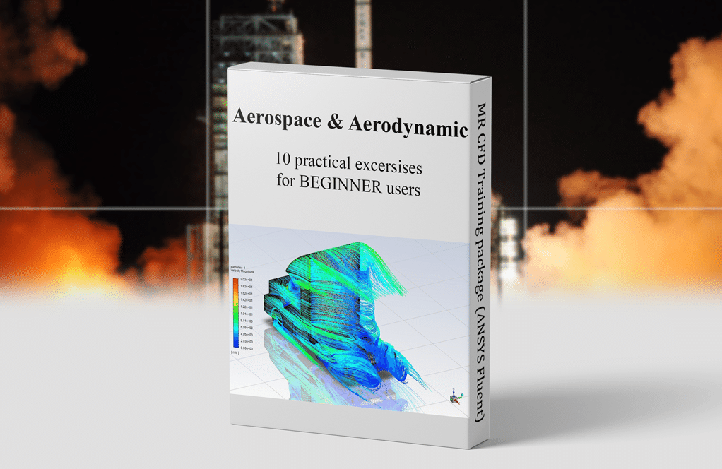
Aerodynamic and Aerospace Training Package for Beginners, 10 Learning Products
Original price was: $840.00.$299.00Current price is: $299.00. Internship
Reviews
There are no reviews yet.