Plate Silencer and Sound Absorption CFD Simulation
$100.00 Student Discount
The present problem simulates the sound pressure waves a plate silencer absorbs using ANSYS Fluent software.
Click on Add To Cart and obtain the Geometry file, Mesh file, and a Comprehensive ANSYS Fluent Training Video.To Order Your Project or benefit from a CFD consultation, contact our experts via email ([email protected]), online support tab, or WhatsApp at +44 7443 197273.
There are some Free Products to check our service quality.
If you want the training video in another language instead of English, ask it via [email protected] after you buy the product.
Description
Plate Silencer and Sound Absorption CFD Simulation (Acoustic), ANSYS Fluent Training
The present problem simulates the sound pressure waves a plate silencer absorbs using ANSYS Fluent software. An acoustic model has been used in the software to simulate and analyze sound or acoustic waves. In general, mechanical waves within a fluid are caused by the vibrations and reciprocating motions of the fluid layers. For example, when a layer of air moves forward in a specific direction, the next layer of fluid pushes itself forward, and the layer returns to its original position. These reciprocating movements of the air layers must continue until the energy within the airflow is depleted.
Now if this number of reciprocating movements reaches more than 16 times per second, the sound is produced. When we hit the surface of a solid object with our hand, the layers of air between our hand and the surface begin to move back and forth; if the number of these round trips is more than 16 times per second, the sound is produced by our hand hitting a solid surface. But, one of the problems in various industries is the production of very loud and abnormal sounds due to the propagation of sound waves. Therefore, in such cases, the use of silencers seems imperative.
The basis of the working mechanism of these mufflers is that by receiving sound waves from the environment, the silencer starts vibration. Finally, the sound wave and the silencer components (plate silencer) mode shapes equalize, and this causes the ambient sound waves to be absorbed by the muffler. To perform such steps, the plate silencer has some plates inside itself. The plates absorb the sound by adapting their mode shapes due to the vibration caused by the sound waves. These mufflers are used in various industries such as metallurgy, power, mining, subway tunnels, automotive, and interior architecture.
The material and type of design of the silencers are such that they can absorb the sounds produced with different frequencies, and in the range of human hearing from 63 to 800 Hz, they can provide the conditions of environmental comfort in terms of sound. Simulation and analysis of these silencers are of great importance; Because if designed incorrectly, the muffler will not only not be able to absorb sound but also increase the sound problems. In the present project, a plate silencer is modeled with a symmetrical structure with a sinusoidal or wavy plate in the middle of its body.
In this simulation, it is assumed that the desired pressure waves have already been created inside this muffler, and our work aims to investigate the behavior of these waves in the longitudinal direction of this muffler and also the plate silencer efficiency. To define the acoustic model in the present simulation, the Ffowcs-Williams & Hawkings model is used. Definitive density is equivalent to air density, ie 1.225 kg / m3, sound speed is equivalent to sound speed in the air, i.e., 340 m / s, and reference acoustic pressure is equal to 0.00002 pascals. Acoustic sources are also defined near the airflow inlet boundary.
In this modeling, airflow enters the muffler at a speed of 1.461 m.s-1 and a temperature of 403.15 K and exits at a pressure equal to the ambient pressure. The plate of the silencer system consists of three parts, which are smooth in the initial and final parts of the system and have a structure with wavy geometry in the middle part of the system that shows a specific vibration mode shape. These plates of are made of aluminum and have a heat transfer coefficient of 20 W.m-2.K-1. Also, the surrounding environment with a free stream temperature equals 298.15 K.
Geometry & Mesh
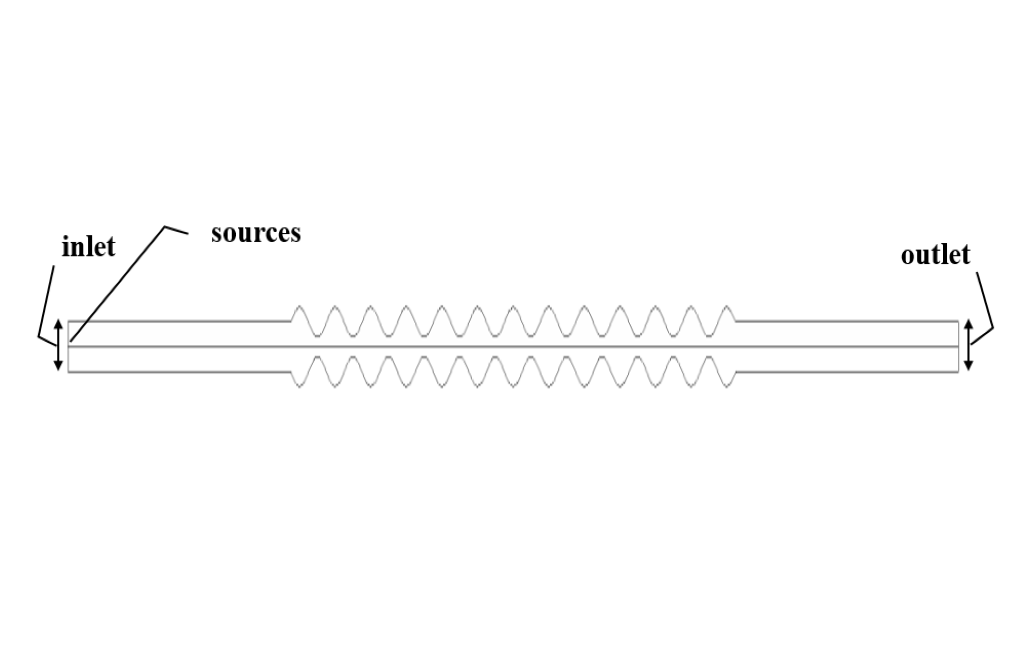
The present model is designed in two dimensions using Design Modeler software. The model has a symmetrical structure whose middle wall has a sinusoidal and wavy structure. Adjacent to the airflow inlet boundary, a section is defined as the source of sound wave propagation. The wavy plate is drawn in such a way that it has a wave amplitude of 0.015 m.
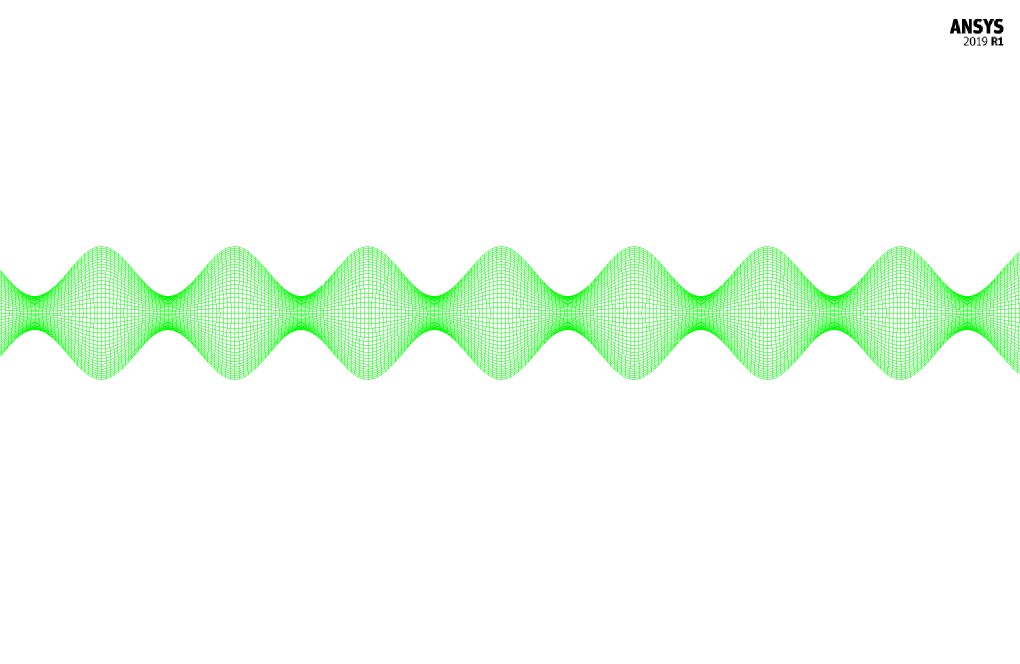
The meshing of the model has been done using ANSYS Meshing software and the mesh type is structured. The element number is 17000. The following figure shows the mesh.
CFD Simulation
To simulate the present model, several assumptions are considered:
- We perform a pressure-based solver.
- The simulation is unsteady because the purpose of this simulation is to investigate the behavior of acoustic waves over time.
- We ignore the gravity effect on the fluid.
The following table represents a summary of the defining steps of the problem and its solution:
| Models | ||
| Viscous | k-epsilon | |
| k-epsilon model | realizable | |
| near wall treatment | enhanced wall treatment | |
| Acoustics Model | Ffowcs-Williams & Hawkings | |
| far-field density | 1.225 kg.m-3 | |
| far-field sound speed | 340 m.s-1 | |
| Reference acoustic pressure | 0.00002 pascal | |
| Energy | On | |
| Boundary conditions | ||
| Inlet | Velocity Inlet | |
| velocity magnitude | 1.461 m.s-1 | |
| temperature | 403.15 K | |
| Outlet | Pressure Outlet | |
| gauge pressure | 0 pascal | |
| Wave Walls | Wall | |
| wall motion | stationary wall | |
| free stream temperature | 298.15 K | |
| heat transfer coefficient | 20 W.m-2.K-1 | |
| Methods | ||
| Pressure-Velocity Coupling | SIMPLE | |
| Pressure | second order | |
| momentum | second-order upwind | |
| turbulent kinetic energy | second-order upwind | |
| turbulent dissipation rate | second-order upwind | |
| energy | second-order upwind | |
| Initialization | ||
| Initialization methods | Standard | |
| gauge pressure | 0 pascal | |
| axial velocity | 1.461 m.s-1 | |
| radial velocity | 0 m.s-1 | |
| temperature | 403.15 K | |
Results
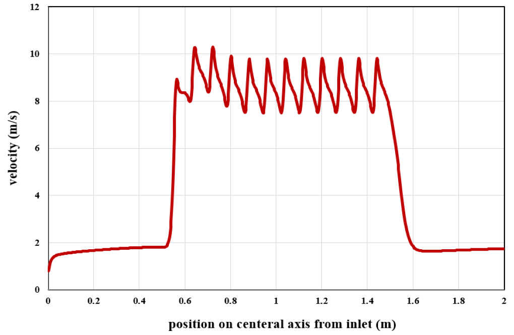
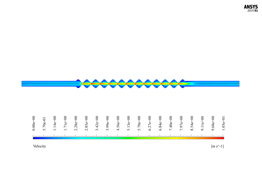
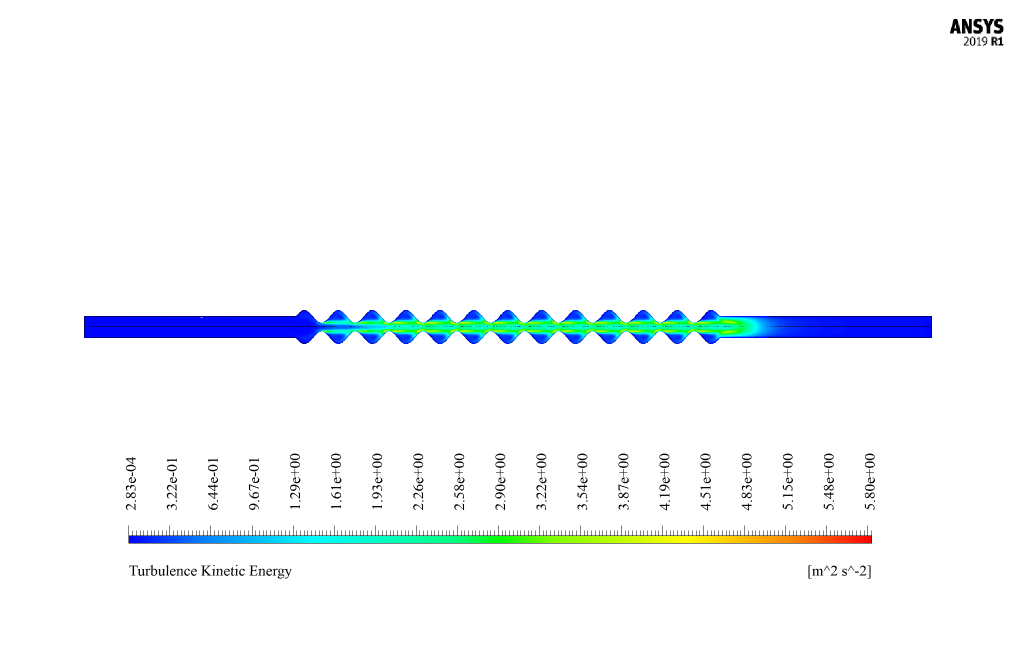
At the end of the solution process, we obtain two-dimensional counters related to pressure, velocity, and temperature, as well as diagrams of velocity changes along the central axis of the system. Also, we present the inlet and outlet receivers’ Sound Pressure Levels (dB) in terms of different frequencies. Finally, you can see the Transmission Loss diagram.





Emily O’Kon –
After reading such an extensive description, I would like to know if the sound absorption properties vary with different materials used for the plates in the silencer.
MR CFD Support –
Good question! Yes, the sound absorption properties vary with different materials for plate silencers. This simulation uses aluminum plates, which have a specific vibration mode shape essential for absorbing sound waves of certain frequencies. Changing the material could alter the vibration characteristics and thus the sound absorption efficiency at various frequency ranges.
Devonte Larkin –
Could this plate silencer model be used to effectively reduce noise in automotive exhaust systems, and how efficient is it in absorbing low-frequency sounds typically found in vehicles?
MR CFD Support –
The plate silencer designed in this simulation is capable of absorbing a broad range of frequencies and can be utilized in various industries, including automotive. For low-frequency noise common in exhaust systems, the materials and design elements, such as the wavy structure of the plate, contribute to its efficiency in noise absorption and assist in damping exhaust system vibrations.
Shayne Ernser I –
I am truly impressed by the detailed approach taken to simulate sound absorption using the plate silencer! It seems like a sophisticated use of the acoustic modeling afforded by ANSYS Fluent.
MR CFD Support –
Thank you for your positive feedback! We’re glad to hear that you are pleased with the thoroughness of our simulation and the capabilities of the acoustic modeling in ANSYS Fluent! If you have any more questions or need further information, feel free to reach out.
Dennis Bayer IV –
Your Plate Silencer ANSYS Fluent Simulation Course was fantastic! The step-by-step guidance through acoustics modelling was really helpful for understanding how the plate silencer worked. Seeing the mesh setup and running the simulations led me to clearly understand wave propagation and sound absorption techniques. Thank you for a comprehensive course that strikes the right balance between theory and practical application!
MR CFD Support –
We’re thrilled to hear that you found our Plate Silencer ANSYS Fluent Simulation Course both educational and practical. It’s great to know that the course helped you understand the intricacies of sound wave propagation and absorption. Thanks for taking the time to share your positive experience, and we hope you’ll find our other training materials just as useful!
Olin Pollich DVM –
This Plate Silencer and Sound Absorption simulation from MR CFD sounds fascinating! It is wonderful to see how technology can enable a curious mind to explore, and, simulate such complex phenomena tackling real-world issues. The comprehensive approach to mimic the acoustic behavior in silencers using the Ffowcs-Williams & Hawkings model with ANSYS Fluent is commendable. Educational tools like these are a great asset for anyone in the field of acoustics engineering, innovation, or research.
MR CFD Support –
We truly appreciate your kind words and enthusiasm regarding the Plate Silencer and Sound Absorption CFD Simulation. It’s gratifying to know that our commitment to providing high-quality simulation training materials is making a difference for our users. If you have any further thoughts or inquiries, please do not hesitate to reach out!
Prof. Oscar Watsica –
Could you explain more about how the Ffowcs-Williams & Hawkings acoustic model is implemented in this simulation?
MR CFD Support –
The Ffowcs-Williams & Hawkings acoustic model predicts the sound generated by sources on moving surfaces. It is used within the ANSYS Fluent software to account for aerodynamically generated noise. To implement this model in the described simulation of the plate silencer, fluid domains are evaluated for noise generation, taking into account factors such as density, sound speed, external acoustics sources, and material properties. Parameters such as far-field density and speed of sound are taken into account along with reference acoustic pressure to accurately model and analyze sound propagation and absorption within the silencer.
Christophe Larkin –
The training on Plate Silencer and Sound Absorption was excellent and covered all the complex processes clearly. Worth every minute!
MR CFD Support –
Thank you for your kind words! We’re thrilled to hear that you found the Plate Silencer and Sound Absorption CFD Simulation training valuable and informative. Your positive feedback is greatly appreciated.
Laura Langworth –
What are the main applications of this Plate Silencer and Sound Absorption CFD Simulation? Where can this technology be applied practically?
MR CFD Support –
The main applications of this Plate Silencer and Sound Absorption CFD Simulation are in industries such as metallurgy, power generation, mining, subway tunnels, automotive, and interior architecture. This technology is practically applied to control and reduce noise pollution by absorbing sounds produced with different frequencies, particularly in the range of human hearing from 63 to 800 Hz. In practical terms, these silencer systems can be installed in industrial equipment exhausts, HVAC systems, inner spaces of tunnels, and other environments where reduction of sound levels is required for comfort or regulatory adherence.
Ms. Verdie Yundt –
Terrific resource for understanding acoustic simulations! I especially appreciated the explanation of sound absorption phenomena achieved using the Ffowcs-Williams & Hawkings model. Grasping the behavior of sound waves through the image of the mesh design was enlightening.
MR CFD Support –
We’re delighted to hear that you found the explanation of the acoustic phenomena and the simulation model helpful. Visual representations such as mesh designs are indeed indispensable to understanding these complex interactions. Thank you for taking the time to share your positive feedback!
Liliane Willms MD –
The simulation sounds impressive! The level of detail in the process description shows thorough efforts made to produce meaningful results.
MR CFD Support –
Thank you for your kind words! We are delighted to know that our detailed process description met your expectations and that you are impressed with the simulation. Your feedback is much appreciated.
Evelyn Cormier –
What are the applications of the plate silencer and can it be customized for various frequency ranges?
MR CFD Support –
Plate silencers are versatile tools found in a variety of industries including metallurgy, power, mining, subway tunnels, automotive, and interior architecture where noise reduction is critical. Yes, the design and materials used for the plate silencers can be tailored to absorb different sound frequencies, ensuring that they are effective in the human audible range of 63 to 800 Hz for environmental comfort regarding sound.
Ahmad Douglas –
It was really fascinating to see how the acoustic waves behave using the simulation. The visualizations of the temperature, pressure, and velocity contours provided great insight into the silencer efficiency. Kudos on providing a comprehensive analysis!
MR CFD Support –
Thank you for your kind words! We’re thrilled to hear you found the simulation and visualizations so enlightening and useful. If you have any more feedback or need further explanations on our products, feel free to reach out!
Justine Huel –
I’m very pleased with the Plate Silencer CFD Simulation course. Encountering a wide range of frequencies, it required precise control and understanding. The training gave me the tools I needed to tackle these challenges successfully.
MR CFD Support –
Thank you for your positive feedback! We are delighted to hear that our Plate Silencer CFD Simulation course met your needs and helped you gain better control and understanding of dealing with different frequencies. Your success is our top priority. If you ever have any more questions or need further assistance, please don’t hesitate to ask.
Prof. Kassandra Fadel PhD –
What’s the benefit of using a Ffowcs-Williams & Hawkings acoustic model in this particular simulation over other acoustic models?
MR CFD Support –
The Ffowcs-Williams & Hawkings acoustic model is beneficial for this simulation because it is specifically designed to handle noise generated by turbulent flows and has been tailored to predict the noise emitted from complex geometries, such as a plate silencer, with a relatively high level of accuracy. Not only does it account for the noise that radiates directly from turbulent flows, it also models the noise generated by the interaction of the turbulent boundary layer with the solid surfaces of the silencer plates.
Prof. Coby Ledner II –
I’m really pleased with how comprehensive the simulation for the plate silencer sound absorption was! The details about how the muffler adjusts to absorb sound waves by vibration and match the wave shapes were especially enlightening. The simulations ANSYS Fluent handles continue to impress me, and it’s fascinating to consider their applications in industrial acoustics. Fantastic work on displaying practical implications and how digital models can validate silencer designs before physical prototyping.
MR CFD Support –
Thank you so much for your kind words! We are delighted to hear that you found the simulation comprehensive and the insights provided on the plate silencer to be enlightening. It’s wonderful to see our customers appreciate the effort our team puts into creating accurate and useful simulations using ANSYS Fluent. Your recognition of our work is highly valuable to us, and we look forward to providing you with more high-quality learning products in the future. Thank you for choosing MR CFD Company as your learning resource!
Napoleon Wisoky –
Does the Plate Silencer in this simulation perform effectively across the full human auditory range, especially in the higher frequencies around 800 Hz?
MR CFD Support –
In this simulation, the Plate Silencer is designed to effectively absorb sounds within the human auditory range, which typically extends from about 20 Hz to 20 kHz. The material and structural design of the plates, particularly the wavy part, target the absorption of various sound frequencies. While the description specifies an emphasis on comfort in the range from 63 to 800 Hz, judging effectiveness at higher frequencies around 800 Hz would necessitate analyzing the Sound Pressure Levels (dB) and the Transmission Loss diagram provided by the simulation results. If designed correctly, the Plate Silencer should perform efficiently across the full range, particularly focusing on the specified frequency span, including the higher 800 Hz range.
Mrs. Julie Kuphal DDS –
I appreciate the detailed explanation of your Plate Silencer and Sound Absorption CFD Simulation training. The incorporation of acoustic modeling is fascinating. I am curious about how the simulation accounts for differing frequencies of sound. Does the model adjust dynamically to accommodate a spectrum of frequencies within human auditory range, or is it optimized for a specific frequency range?
MR CFD Support –
The CFD simulation of the Plate Silencer includes provisions to account for a spectrum of sound frequencies. The setup is done using the Ffowcs-Williams & Hawkings acoustic model which allows for the analysis of sound wave propagation in the fluid medium across a range of frequencies. Specifically, it absorbs sounds with different frequencies, and efficiency in the range of human hearing from 63 to 800 Hz, ensuring the model is relevant for scenarios concerning environmental acoustic comfort.
Minnie Mitchell –
I appreciated the Plate Silencer simulation training. I particularly found the detailed step-by-step setup information useful for setting up my own simulations. The inclusion of the acoustic models enhanced my understanding of the complexity involved in silencer design.
MR CFD Support –
Thank you for taking the time to leave a positive review on our Plate Silencer training module. It’s wonderful to hear that the detailed setup information and the inclusion of acoustic models were beneficial for your learning and practical application. Your feedback is greatly appreciated!