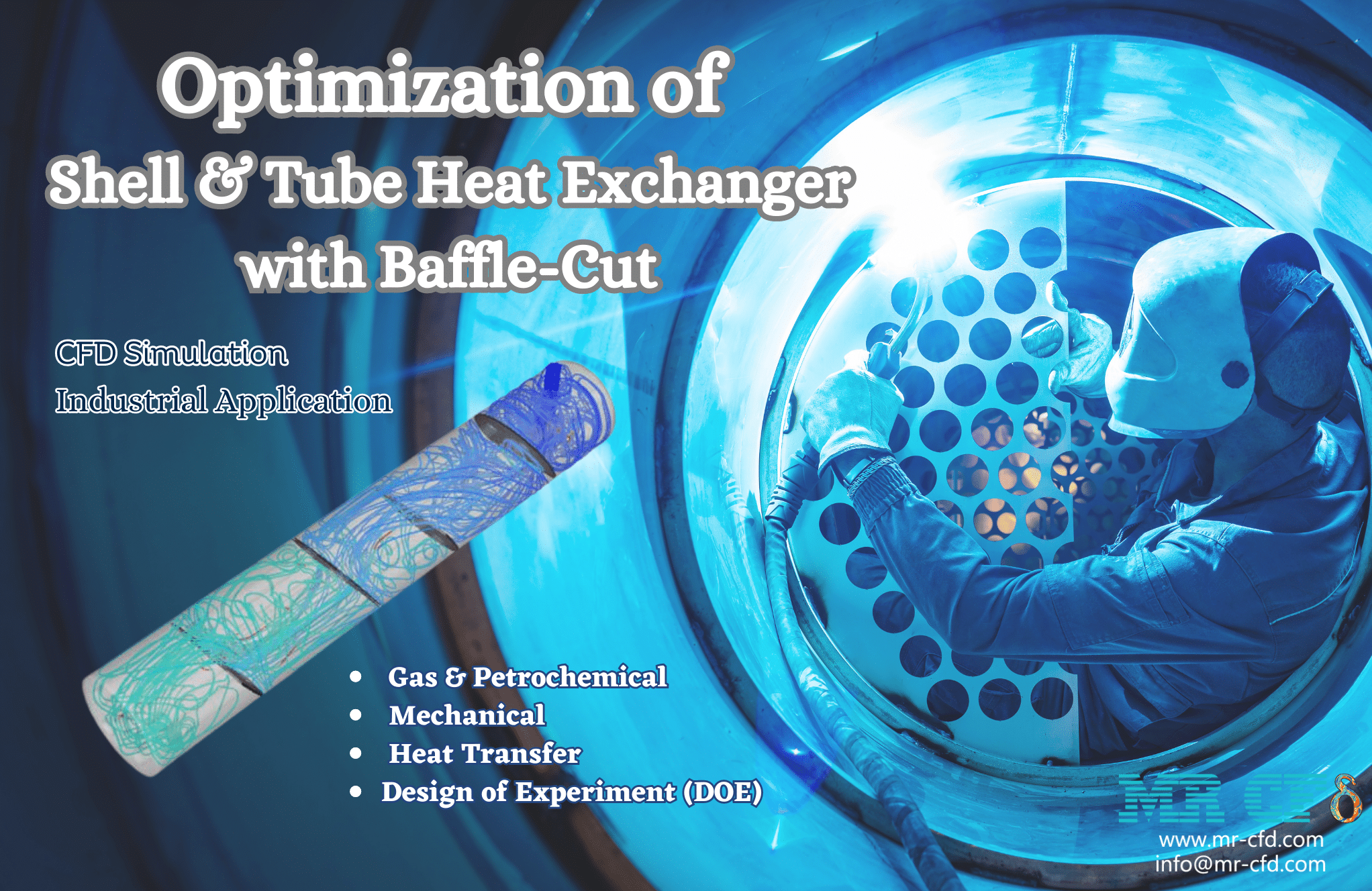
Optimization of Shell & Tube Heat Exchanger with Baffle-Cut, Industrial CFD Simulation
$180.00 Student Discount
In this project, an industrial CFD simulation of the Optimization of Shell & Tube Heat Exchanger with Baffle-Cut has been carried out, and the simulation results have been investigated.
Click on Add To Cart and obtain the Geometry file, Mesh file, and a Comprehensive ANSYS Fluent Training Video.To Order Your Project or benefit from a CFD consultation, contact our experts via email ([email protected]), online support tab, or WhatsApp at +44 7443 197273.
There are some Free Products to check our service quality.
If you want the training video in another language instead of English, ask it via [email protected] after you buy the product.
Description
Introduction
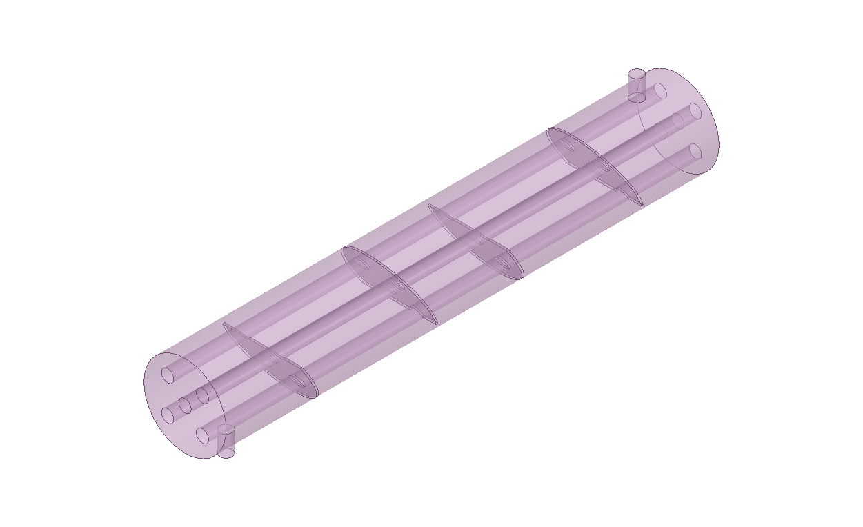
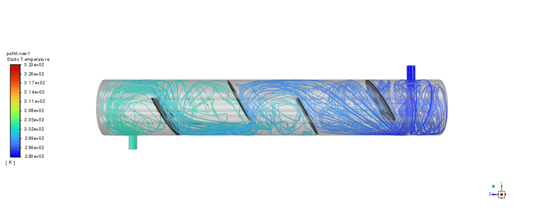
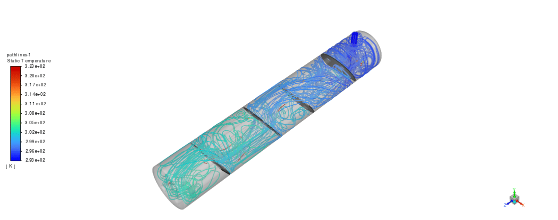
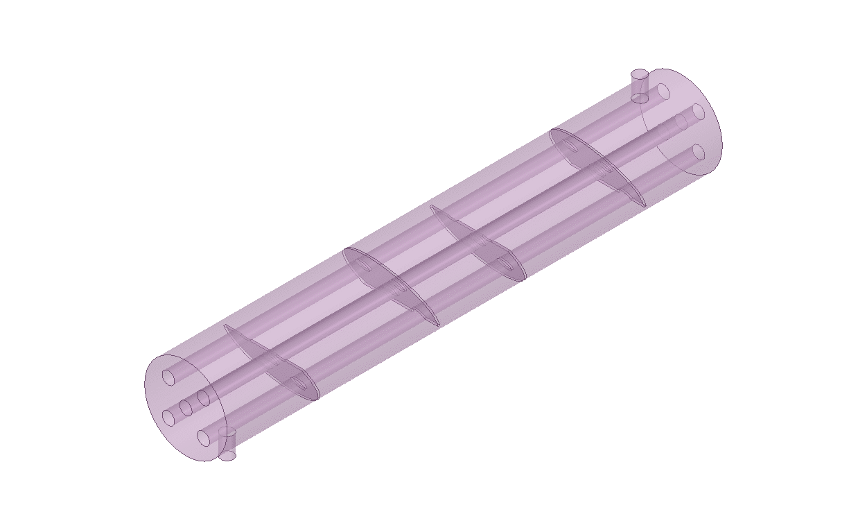
Before the advent of modern optimization software, engineers and scientists used classical optimization techniques to find optimal solutions. For better understanding, let`s assume an industrial and practical case study like a shell and tube heat exchanger, shown in the figures below. This shell and tube heat exchanger has 4 baffle cuts and 5 hot tubes in the center.
We aim to increase heat transfer while trying to minimize pressure drop. Notice that we can only change the mass flow of the inlet water, the baffle-cuts angle, and the diameter of hot tubes. Previously, in the classical optimization procedure, we simulated 10 designs, for example, and then chose the best-case scenario, but there was a problem.
There was more than 100 possible design, and we just picked the optimal design by testing just 10 of them! Thus, this couldn`t be called a real optimization! We`ve got an alternative now known as the Design of Experiment (DOE). Simply put, we can now choose the optimal design for all possible designs!!!
The basic idea of DOE is to vary the values of the design variables in a controlled manner and observe the resulting changes in the response variable. It involves several steps, which will be discussed In the following, by considering the same heat exchanger problem.
Project Description
A shell and tube heat exchanger is a type of heat exchanger that uses a shell (a large pressure vessel) to contain a bundle of tubes through which a fluid is circulated to exchange heat with another fluid. It is commonly used in industrial applications for heating or cooling large quantities of fluids.
In this project, we aim to find the optimal design of a shell and tube heat exchanger equipped with baffle cuts using ANSYS Workbench modules. The figure below shows a shell and tube heat exchanger with 4 baffle cuts and 5 hot tubes in the center.
The geometry is designed using ANSYS Design Modeler software. The computation domain was then divided into about a million tetrahedron cells via ANSYS Meshing software. The following figure shows the mesh grid:
Optimization
As mentioned, our target is the Optimization of Shell & Tube Heat Exchanger by increasing heat transfer while minimizing pressure drop. Numerical and equivalent output parameters should measure these objective functions. For example, the temperature of the fluid at the outlet can represent the heat transfer changes, and the pressure drop can be measured directly.
On the other hand, we can only change the mass flow of the inlet water, the baffle-cuts angle, and the diameter of the hot tubes. These three variables are known as input parameters/variables in optimizations. Also, we can change the input parameters in a specific range that are selected based on experience, doable, limitations, predictions, etc. For the current project, all of the data is summarized in the table below:
| Input Variable | Range | Output |
| Baffle-cut angle (P1) | (-30°) – (+30°) | Outlet Temperature
Pressure Drop |
| Tubes diameter (P2) | (10)-(25) cm | |
| Inlet Mass Flow (P3) |
(2)-(4) kg/s |
The P1, P2 & P3 are marked in the figure below:
Optimization of Shell & Tube Heat Exchanger Methodology
All the optimization steps have been done by ANSYS Workbench software. This optimization has been done using Multi-Objective Genetic Aggregation. Also, the CCD algorithm is used as a Design of Experiments step, and Genetic Aggregation is used as an RSM step.
Results
The following table shows all the design points generated by the CCD method and the results extracted from executed simulations. By using these proposed 15 design points and its results, all other designs can be estimated. So we are looking for optimal design considering all possible designs, not just a limited number.
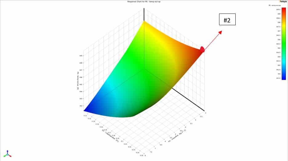
The second step is to generate response surfaces based on the Genetic aggregation method. The following figures are just some of the extracted response surfaces that can clearly show the effect of changing input parameters on objective functions.
For example, it can be seen that increasing the baffle-cut angle can increase the pressure drop in a specific range. The optimal point might be around point #1, marked in the figure in red color by just considering the pressure drop objective function. Furthermore, increasing the inlet’s mass flow could not unexpectedly enhance heat transfer.
So this time, point #2 may be a better design point. Many points like these can be candidates for optimal design depending on our prior criteria. Considering all the input parameters and the targets, there is a tradeoff that should be analyzed carefully in order to find the optimal design.
This process will be done in the third step of the optimization procedure using ANSYS Workbench software. After a quick analysis, the software gives us 3 best candidate points considering ALL OBJECTIVE FUNCTIONS and ALL INPUT VARIABLE RANGES. In other words, among all possible scenarios, not just limited ones.
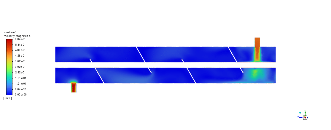
As illustrated, using 17cm tubes, -30° baffle-cut angle, and 2 kg/s mass flow, the outlet temperature reaches 308.18K while experiencing just an 8.52 Pa pressure drop through the shell.







Marquise Ankunding –
The review beautifully explains the intricacies of optimizing a shell and tube heat exchanger. I found the multi-objective design approach intriguing. Is there any insight into how changing the baffle-cut angle influences the temperature distribution across the heat exchanger?
MR CFD Support –
In the process of optimization for the shell and tube heat exchanger, changing the baffle-cut angle impacts the flow pattern and turbulence levels within the shell side, which in turn affects the heat transfer between the shell and tube fluids. Higher angles can increase turbulence, which enhances heat transfer but can also lead to a higher pressure drop. The described methodology uses a genetic aggregation method to analyze the trade-offs. The response surfaces provided can illustrate the impact on temperature distribution, showing that for certain angles, there might be an optimal balance between heat transfer and pressure drop. Detailed temperature distribution results would be extracted from the simulation data not mentioned directly in the review.
Chelsea Swift –
What are the main advantages of using the DOE method over classical optimization techniques in heat exchanger optimization?
MR CFD Support –
The primary advantages of using the Design of Experiments (DOE) method in heat exchanger optimization are the ability to systematically explore all possible design permutations within the defined ranges and the capacity to identify the impact of various design variables on output parameters. This thorough exploration results in a more accurate and reliable identification of the optimal design, as opposed to the classical methods that may only sample a small subset of the possible designs.
Dr. Zack Friesen –
What a detailed breakdown of the optimization process! I’m intrigued by the use of the Design of Experiment (DOE) approach. Could you explain a bit more about how the Multi-Objective Genetic Aggression and the CCD algorithm work together in the ANSYS Workbench software for this optimization?
MR CFD Support –
The Multi-Objective Genetic Aggregation and CCD algorithm in ANSYS Workbench work together by first using the CCD (Central Composite Design) algorithm to carefully select design points that consider the full spread of possible variable combinations. This structured approach helps explore the design space more efficiently. Following this, Multi-Objective Genetic Aggregation (MOGA) uses genetic algorithm principles to iterate through various design ‘populations,’ evolving the solutions to converge on an optimal design that balances multiple objective functions. Genetic algorithms simulate natural selection processes to find the most optimal solutions. By combining both methods, a robust and reliable optimization can be performed considering multiple factors in the design space.
Ona Hilpert –
I was blown away by the detail and thoroughness of the DOE approach for determining the optimal design! After tuning those variables, how did the outlet temperature and pressure drop in the optimal scenario compare to one of your baseline designs?
MR CFD Support –
I’m glad you appreciated the depth of the optimization process! Your query addresses a key outcome of the design optimization. In the optimal design scenario using 17cm tubes, a -30° baffle-cut angle, and 2 kg/s mass flow, the outlet temperature is 308.18K with a pressure drop of just 8.52 Pa. Compared to the initial baseline designs, this represented a notable improvement, achieving an optimal balance between heat transfer enhancement and pressure drop reduction—a result of the comprehensive DOE optimization approach implemented in ANSYS Workbench software.
Claudia Wiza –
I’m excited about the results shown in the simulation, but how does the optimization handle the tradeoffs between pressure drop and heat transfer to find the best design?
MR CFD Support –
The optimization process uses a tradeoff analysis to simultaneously consider multiple objective functions. It uses a Genetic Aggregation method to compromise between the pressure drop and heat transfer, resulting in candidate designs that balance the two. The final selection is made based on the predefined priorities and criteria within the input variable ranges.
Jason Hansen DVM –
The detailed information on the optimization process is well explained, providing valuable insights for users looking to adapt their simulation parameters for optimal efficiency. Great job breaking down such a complex process into understandable terms.
MR CFD Support –
Thank you for your positive feedback! We are thrilled to hear that our efforts in breaking down complex CFD simulations into more understandable information are helping our users. If you have any further questions or need assistance with your simulations, feel free to reach out to us.
Madelynn Wilderman –
I’m really impressed with the results! Can you tell me, does DOE typically result in higher costs compared to traditional methods, considering we’re looking at all design possibilities in DOE?
MR CFD Support –
In the short term, utilizing DOE might appear costlier because it involves evaluating a broader range of design variations compared to a classical approach. However, the intent is to converge on an optimal solution without exhaustive trial-and-error simulations. Ultimately, DOE’s systematic and comprehensive nature often leads to more efficient and effective designs in the long run, saving time, resources, and increasing overall value.
Nathanial Altenwerth –
I’m impressed with the CCD method used for the Design of Experiments! Could you tell me more about how the Genetic Aggregation method contributes to finding the optimal design?
MR CFD Support –
The Genetic Aggregation method combines the concept of evolutionary algorithms with response surface methodology. In the context of this heat exchanger optimization, it helps to create a mathematical model or surface plot representing the relationship between the input variables and output parameters based on the data from the design points. These surface plots allow us to visualize how changes in variables, like baffle-cut angle or tubes diameter, affect the performance objectives such as heat transfer efficiency or pressure drop. Consequently, we can use these models to predict the best compromise or ‘trade-off’ solutions, directing us toward the most optimal designs that meet our specified criteria.
Blair Grady –
The optimization procedure seems quite comprehensive and scientific. Could you explain how the genetic aggregation method contributes to the accuracy of the optimization process?
MR CFD Support –
The genetic aggregation method is part of the optimization process that helps to combine multiple objectives into a single, scaler objective function while considering the variability of multiple input parameters. It uses techniques inspired by natural evolution, such as mutation, selection, and crossover to explore the search space effectively. By doing so, it contributes to the accuracy by finding an optimal balance between different objectives, such as maximizing heat transfer and minimizing pressure drop, which would be challenging to achieve manually.
Lora Graham –
Are there other variables aside from the mass flow rate, baffle-cut angle, and tube diameter that could have been adjusted to optimally increase the heat transfer and minimize pressure drop, or is their choice based on typical industry standards?
MR CFD Support –
In industrial practice, many variables can impact the optimal functioning of a heat exchanger. However, for this specific project, the mass flow rate, baffle-cut angle, and tube diameter were chosen based on standard optimization criteria that typically influence the efficiency of shell & tube heat exchangers. Their adjustability could be constrained by design limitations, manufacturing capabilities, and the intended application of the heat exchanger.
Mrs. Alana D’Amore V –
I’m truly impressed by the thorough optimization approach! What CCD algorithm stands for, and how does it differ from simple trial-and-error methods previously used?
MR CFD Support –
CCD stands for Central Composite Design, which is a statistical technique for building a second-order (quadratic) model for the response variable without needing to test all possible combinations. It significantly reduces the number of experimental runs or simulations needed compared to full factorial designs. Unlike trial-and-error, CCD provides a systematic approach to understanding the interactions between variables and efficiently finds optimal solutions.
Prof. Marjolaine Reynolds IV –
I appreciate the detailed walkthrough of the optimization process, and the advanced use of optimization theory like DOE (Design of Experiment) to systematically find the optimal shell and tube heat exchanger design. These innovative methods surely pave the way for more efficient and accurate engineering results. Well done on seamlessly integrating CAD design, CFD analysis, and numerical optimization within ANSYS Workbench. Inspiring work indeed!
MR CFD Support –
Thank you so much for your positive review! We’re delighted to hear that you found the optimization procedure informative and that our use of DOE along with ANSYS Workbench provided you with valuable insights. Your recognition of the integration of CAD, CFD, and numerical optimization encourages us to continue providing high-quality learning materials. If you have any more feedback or need further assistance, feel free to reach out!