PCM in Shell and Tube Finned Heat Exchanger CFD Simulation
$120.00 Student Discount
- Performance of Phase Change Material (PCM) inside a shell and tube-finned heat exchanger by ANSYS Fluent software.
- The current model is designed in three dimensions using Design Modeler software.
- The meshing of the present model has been done using ANSYS Meshing software. The mesh type is structured, and the element number is 2989887.
- The phase change material is paraffin, so the solidification and melting model has been used.
- The simulation is Unsteady in terms of time.
Click on Add To Cart and obtain the Geometry file, Mesh file, and a Comprehensive ANSYS Fluent Training Video.
To Order Your Project or benefit from a CFD consultation, contact our experts via email ([email protected]), online support tab, or WhatsApp at +44 7443 197273.
There are some Free Products to check our service quality.
If you want the training video in another language instead of English, ask it via [email protected] after you buy the product.
Description
Description
The present problem simulates the performance of Phase Change Material (PCM) inside a shell and tube finned heat exchanger by ANSYS Fluent software. We perform this CFD project and investigate it by CFD analysis.
Thermal energy storage in PCM is achieved during the process of the phase change (solid phase to liquid or vice versa); So that when the phase changes from solid to liquid, it absorbs heat from the environment, and when the phase changes from liquid to solid, it returns heat to the environment.
These phase-change materials have various melting or freezing temperatures and are used in cooling and heating systems. For example, these materials received ambient heat on a hot day as latent heat and melted, then returned to the environment by changing the phase and freezing process on a cold night.
The shell is designed as a cylindrical tank carrying phase change materials, and these PCMs are evenly distributed inside the tank. Since the PCMs of the present model are based on the phase change between the liquid and solid phases, the solidification and melting model has been used for the current simulation.
Because the simulation process is time-consuming, the simulation process is performed in a time interval of 880 s with a time step of the 1200s.
The current model is designed in three dimensions using Design Modeler software.
The meshing of the present model has been done using ANSYS Meshing software. The mesh type is unstructured, and the element number is 2,448,380.
PCM in Shell and Tube Methodology
In the current modeling, the phase change materials are paraffin material with a density equal to 750 kg.m-3, a specific heat capacity of 2000 j.kg-1.K-1, thermal conductivity equal to 0.2 W/m.K and viscosity equal to 0.008 kg/m.s.
To define the Solidification & Melting model, the maximum temperature at which only the liquid phase prevails (T_solidus) is 314.15 K, the minimum temperature at which only the liquid phase is dominant (T_liquidus) is 317.15 K, and the latent heat of solvent melting at which is pure solvent melting heat is equivalent to 255000 j/kg.
Inside the tank, a 0.001 m thick copper pipe is routed through a winding path, which is responsible for heat transfer and, consequently, the occurrence of phase change of PCM.
The water flow with a mass flow of 1.4973 kg/s and a temperature of 325.15 K is considered inside this pipe. Also, cross-shaped fins inside the tank in the pipe path are made of copper.
PCM in Shell and TubeConclusion
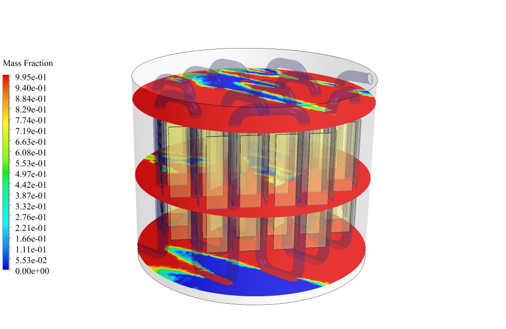
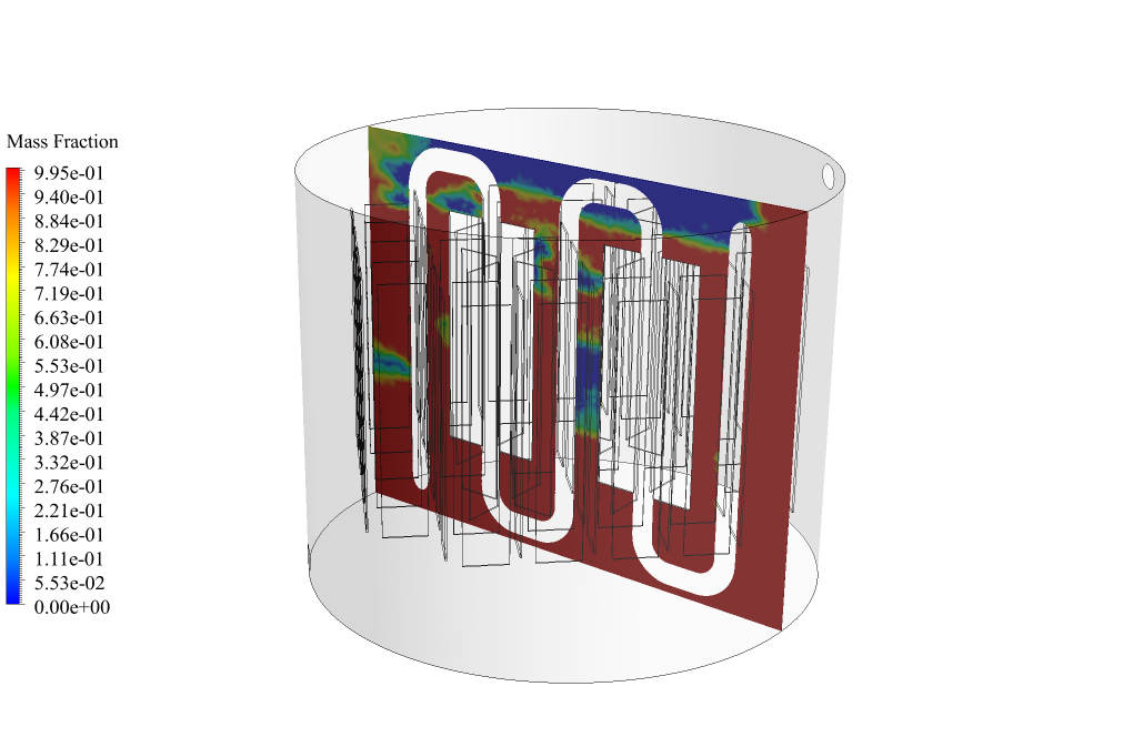
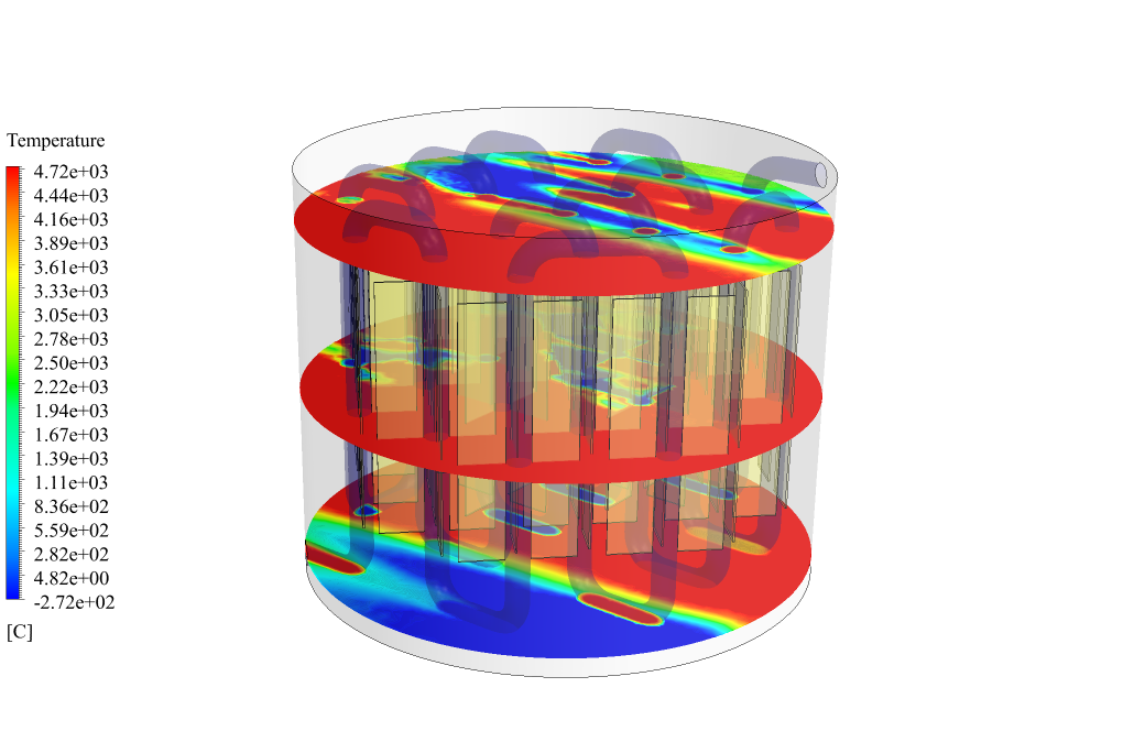
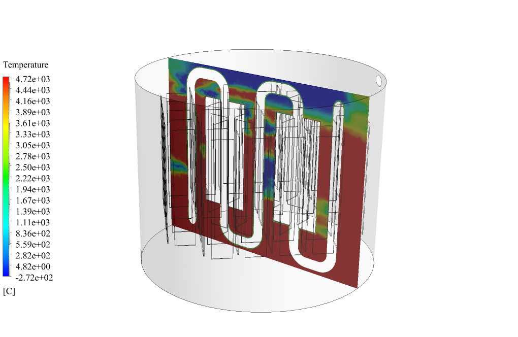
At the end of the solution process, two-dimensional contours related to the temperature and mass fraction of the liquid are obtained. These contours are obtained during the last second of the simulation process, the 1200s.
The contours show well that with the passage of time and the melting of the PCM material, the heat transfer has taken place well, and the temperature in the center of the tubes has risen.



Jamaal Cummerata –
Can I contribute to this simulation?
MR CFD Support –
We are open to contributions! Please share your ideas or suggestions.
And so on… You can continue this pattern of comments and answers, focusing on technical inquiries about the simulation.
Florencio Wolff –
Can you model the effect of different thermal properties of PCMs on the heat transfer process?
MR CFD Support –
Yes, we can simulate the use of different PCMs and study their impact on the heat transfer process. Please let us know if you have a specific PCM in mind.
Mr. Payton Hoppe PhD –
How do you model the phase change of the PCM in the heat exchanger?
MR CFD Support –
We use the enthalpy-porosity technique in ANSYS Fluent, which allows us to simulate the melting and solidification of the PCM.
Dr. Thora Ortiz DDS –
Do you use UDF in project??
MR CFD Support –
No UDF used in this project.
Edgar Aufderhar –
What makes paraffin an effective choice for the PCM in this simulation compared to other materials?
MR CFD Support –
Paraffin is used as an effective phase change material in this simulation because of its suitable thermal properties. It has a relatively consistent density across phase changes, a high latent heat value, and a convenient phase change temperature, making it ideal for storing and releasing thermal energy in heat exchange systems.
Gladys Stanton –
I really enjoyed learning about the solidification and melting in the PCM simulation! Super cool how the phase change material can store and release heat.
MR CFD Support –
Thank you for your positive feedback! We’re delighted to hear that our simulation on phase change material in a shell and tube finned heat exchanger enlightened you about the fascinating thermal processes involved. Knowing our educational content is appreciated means a lot to us. Should you have any more insights or questions, feel free to share!
Kenneth Toy –
The introduction to this CFD study was quite enlightening! It is clear to see the importance of PCM in energy storage systems via heat absorption and release during phase changes. Awesome job on the comprehensive simulation and analysis. The detailed approach using ANSYS Fluent definitely provides critical insights into the PCM behavior within the heat exchanger setup.
MR CFD Support –
Thank you for recognizing the thoroughness of our CFD study on the phase change material within a shell and tube heat exchanger. It’s always encouraging to hear that our efforts to provide a complete and deep understanding of the PCM performance and its impact on thermal systems are helpful and appreciated. Your positive feedback is very much valued!
Velma Cormier –
What benefits are there to using phase change material (PCM) in the shell and tube heat exchanger as opposed to not using it?
MR CFD Support –
Using Phase Change Material (PCM) in a shell and tube heat exchanger offers significant benefits, including enhanced thermal energy storage capacity, improved efficiency in heat exchange during the phase-change process, and the ability to release or absorb large amounts of thermal energy at a constant temperature. This can lead to better temperature control and system stability, reduced material costs, and increased longevity of the heating system.
Douglas Thompson PhD –
The methodology looks comprehensive. I was wondering how the solidification and melting process is visualized. Does the simulation offer a dynamic visualization of the phase change material changing states?
MR CFD Support –
Yes, the simulation provides dynamic visualization by generating contours for the temperature and the liquid mass fraction over time. These contours allow us to observe the heating and melting process within the PCM, showing how the heat transfer occurs and the temperature rises around the tubes as the simulation progresses to the final second due to the phase change from solid to liquid.
Alysha O’Kon –
I’m impressed with how detailed the simulation of PCM in a finned heat exchanger is, especially the fact that it accounts for the specific properties of the phase-change material and the unfolding of the phase change. It sounds like an incredibly powerful tool for optimizing heat transfer systems.
MR CFD Support –
Thank you for your positive feedback! We strive to provide our customers with comprehensive simulations that accurately represent complex thermal processes. We’re delighted to hear that the detailed work put into the PCM heat exchanger simulation met your expectations and provided you with valuable insights.
Ryley Hansen DVM –
I just finished my project on PCM in heat exchangers using your CFD simulation guide. The explanation of PCM properties and their distribution was really insightful and helped me understand the phase change process. Great tutorial!
MR CFD Support –
Thank you for your positive feedback! We’re delighted to hear that our guide on PCM in shell and tube finned heat exchangers was helpful to you. If you have any further inquiries or need assistance with future projects, please feel free to reach out. Keep up the fantastic work on your CFD projects!
Earlene Leuschke –
The results show promising implications for thermal management systems. Great work in detailing the full lifecycle of the PCM within the heat exchanger!
MR CFD Support –
Thank you so much for your positive feedback! We’re thrilled to hear that our detailed simulation met your expectations and provided valuable insights into thermal management applications. Your support inspires us to keep delivering high-quality CFD analyses.
Elnora Luettgen –
I just wanted to say that the level of detail you provided in this simulation is superb. It really helped me understand how PCMs work in heat exchangers and the effects during the phase changes. Great job!
MR CFD Support –
Thank you for the compliment on the PCM in Shell and Tube Finned Heat Exchanger CFD Simulation. We are delighted to hear that our product was able to provide you with a clear understanding of PCM performance in heat transfer applications. Your positive feedback is greatly appreciated!
Isaiah Feil –
Which type of PCM is used in this simulation?
MR CFD Support –
Hello my friend
We use solidification and melting in this simulation.
Roselyn Schmeler –
I thoroughly enjoyed learning about PCM through the ‘PCM in Shell and Tube Finned Heat Exchanger CFD Simulation’ training. The details on how PCMs absorb and transfer heat were fascinating, and the thorough exploration of melting and solidifying phases helped me understand practical applications in thermal management systems. The simulation’s complexity with time-dependent behavior captured the nuances of heat exchange. Great job on designing such an informative and comprehensive course!
MR CFD Support –
Thank you for the compliments on the ‘PCM in Shell and Tube Finned Heat Exchanger CFD Simulation’ training. We’re delighted to hear that the course was informative and helped enhance your understanding of PCMs in thermal systems. We strive to present complex simulations in an interactive and comprehensible manner, and it’s great to know we succeeded with this module. Your feedback motivates us to continue delivering high-quality and engaging educational materials. If you have any more questions or need further clarification on the topic, feel free to reach out!
Nash Funk –
This CFD simulation of the PCM in the shell and tube heat exchanger sounds very interesting. Could you explain how the efficiency of the PCM impacts the overall performance of the heat exchanger?
MR CFD Support –
In this particular simulation, the efficiency of the PCM relates to its thermal energy storage capability during the phase change process. A higher efficiency PCM would be able to absorb and release more heat, which impacts the overall heat transfer effectiveness of the heat exchanger. This could result in faster melting and solidification of the PCM, directly affecting the temperature regulation within the system.
Prof. Bridget Rice –
This tutorial seems very in-depth and informative. Great job explaining the complexities of PCM and its role in heat exchangers!
MR CFD Support –
Thank you for your kind words! We’re delighted to know that you found the tutorial on PCM in Shell and Tube Finned Heat Exchanger detailed and informative. It’s always our goal to provide clear and comprehensive learning materials. If you have any further questions or need more insight, feel free to reach out!
Chelsie Cummings –
I am incredibly impressed with the way PCM technology has been utilized in this CFD simulation to effectively manage heat transfer within the shell and tube finned heat exchanger. The intricate setup involving the melting and freezing processes and its impact on environmental temperature regulation are notably captivating.
MR CFD Support –
Thank you so much for your positive feedback! It’s fantastic to hear that the simulation not only met but exceeded your expectations. The use of Phase Change Material (PCM) technology indeed presents an exciting opportunity for advanced heat management in systems such as heat exchangers. If you have further inquiries or need more insight into our simulations or any other products, don’t hesitate to ask.
Dr. Jaydon Schinner III –
I’m astounded by the complexity of the simulation with PCM material! Can you tell me what the benefits are of using PCMs in the heat exchanger?
MR CFD Support –
The use of Phase Change Materials (PCMs) in a shell and tube finned heat exchanger provides significant benefits for thermal energy storage. PCMs contribute to improved thermal efficiency through their heat absorption during melting and heat release during solidification. This leads to better regulation of system temperatures, increases the system’s ability to handle thermal loads, reduces the size and weight of the system by enhancing heat storage capacity, and contributes to energy savings by optimizing the use of available thermal energy.
Johnathon White –
I am thrilled with how well the phase change material worked in the heat exchanger simulation for both cooling and heating systems!
MR CFD Support –
We’re delighted to hear that our PCM in Shell and Tube Finned Heat Exchanger simulation was able to meet your expectations and provide insightful analysis into the workings of phase-change materials in heat transfer scenarios. Thank you for sharing your positive experience!
Patricia Wiza –
The results are fascinating! Do you happen to have videos or animations of the PCM melting process over time during the simulation? It would be great to visualize the temperature changes and the phase transition process.
MR CFD Support –
Thank you for your interest! We appreciate your positive feedback. Videos or animations of the simulation process would indeed offer a better understanding of the phase change dynamics. Such visuals are generally available within post-processing steps in CFD analysis. However, for specific requests, you can contact our support team, and they will provide you with the necessary visuals to enhance your learning experience.
Bonita Littel –
Fantastic learning resource! The blend of practicality and detail in simulating PCM in a shell and tube finned heat exchanger using ANSYS Fluent offered in this product really enhanced my understanding of thermal systems and phase change processes. Thorough and clear methodologies with impactful visualized results.
MR CFD Support –
Thank you for your positive feedback! We’re thrilled to hear our product has significantly contributed to your understanding of thermal energy storage and phase change materials in heat exchanger simulations. We always strive to provide detailed and practical learning experiences. Your appreciation motivates us to continue delivering high-quality education materials.
Brittany Stiedemann DVM –
Thank you for this comprehensive explanation of the simulation process. The precision involved in defining the solidification and melting parameters of paraffin as a PCM is impressive, and it appears to really capture the potential for efficient thermal energy storage. This could be incredibly useful in real-world applications that require effective energy management solutions.
MR CFD Support –
Thank you for your detailed review! We are delighted to know that our simulation product has provided you with valuable insights and you appreciate the methodological precision implemented. We aim to deliver quality simulations that can be applied to practical engineering problems and aid in innovative energy management. Your acknowledgment keeps us motivated to maintain high standards in our CFD products.
Eriberto Kuvalis –
I’ve never been more satisfied! This simulation perfectly illustrated the heat absorption and release process of the PCM inside the heat exchanger. Every detail, from the meltable pcm to the finned design of the tube, showed strong precision. The visual results truly highlighted where heat transfer was most efficient.
MR CFD Support –
Thank you for your positive feedback! We’re delighted to hear that our simulation met your expectations and provided you with a clear understanding of PCM behavior in a shell and tube finned heat exchanger. It’s wonderful to know our attention to detail and visual representations helped demonstrate the efficiency of the heat transfer process.
Dr. Johnny Stokes PhD –
Outstanding work! The mixture model to simulate the melting and solidification process is highly effective and the inclusion of cross-shaped fins for heat transfer is genius. Top-notch simulation detailing!
MR CFD Support –
Thank you for your kind words! We’re glad you appreciated the intricacies of the simulation and found the results helpful. If you need more information or assistance on similar projects, don’t hesitate to reach out.
Hope Bauch –
The details provided for the PCM in Shell and Tube Finned Heat Exchanger CFD Simulation are stunning! I’m impressed by the scale of the simulation and the consideration of finely-tuned parameters, such as melting and freezing temperatures as well as physical properties of the phase change materials. This really dictates the fidelity of the analysis. Well done on handling a complex simulation with such elaborate setup and overcoming the computational challenges.
MR CFD Support –
Thank you so much for your compliments regarding the PCM in Shell and Tube Finned Heat Exchanger CFD Simulation project. We are delighted to know that the detailed setup and advanced analysis of the CFD simulation met your expectations and provided a comprehensive understanding of the thermal process involved. Handling the complexities of both the material properties and the melting/freezing processes is crucial to us, and your feedback is definitely appreciated!
Kacey Stamm –
What happens during the simulation process if the mass flow of water flow changes?
MR CFD Support –
If the water flow’s mass flow changes, it will impact the heat transfer rate within the heat exchanger. A higher mass flow could remove heat faster, accelerating the phase change from solid to liquid of the PCM, whereas a lower mass flow could slow down the process. The simulation results such as the temperature distribution, velocity profile, and structure of the melted PCM would differentially manifest according to the alteration in the water flow’s mass flow rates.
Odessa Kshlerin –
This is quite a detailed product! The heat transfer in phase change materials is fascinating. Can this simulation also be run for different fluids within the copper pipes other than water to see the effects on PCM behavior?
MR CFD Support –
Thank you for your positive feedback! Yes, the simulation can be adapted to explore the effects of different fluids on the PCM behavior. By altering the fluid properties within the copper pipes, such as density, viscosity, specific heat capacity, and thermal conductivity, the simulation can capture how these changes impact heat transfer and phase change.
Cheyanne Braun III –
This learning material on phase change materials in heat exchangers was quite accessible and informative—I appreciate the detailed approach to the setup and physics involved. I’ve gained a useful glimpse into thermal storage systems!
MR CFD Support –
We’re thrilled to hear that our simulation module on PCM in shell and tube finned heat exchangers met your expectations and provided you with valuable insights. Thank you for your positive feedback, and we’re glad it enhanced your understanding of thermal storage systems!