
Diesel Fuel in a Gas Turbine Combustion Chamber
$140.00 Internship
- The problem numerically simulates Diesel Fuel in a Gas Turbine Combustion Chamber using ANSYS Fluent software.
- We design the 3-D model by the Design Modeler software.
- We mesh the model with ANSYS Meshing software, and the element number equals 3488057.
- We use the species transport model to define the combustion process.
To Order Your Project or benefit from a CFD consultation, contact our experts via email (info@mr-cfd.com), online support tab, or WhatsApp at +44 7443 197273.
There are some Free Products to check our service quality.
If you want the training video in another language instead of English, ask it via info@mr-cfd.com after you buy the product.
Description
Diesel Fuel in a Gas Turbine Combustion Chamber, ANSYS Fluent CFD Simulation Tutorial
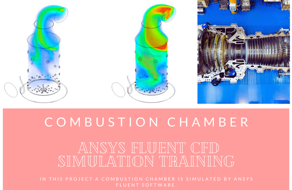
The problem is simulating the combustion process of diesel fuel inside a combustion chamber of a gas turbine system by ANSYS Fluent software. We perform this CFD project and investigate it by CFD analysis.
The function of the combustion chamber is such that the airflow enters the chamber from the space around the chamber and then passes through a diffuser duct with blades, becomes disturbed, and enters the special combustion space in order to better mix with the fuel.
On the other hand, the fuel flow is injected into the space inside the chamber through a nozzle and is mixed with the gas flow, and as a result, the combustion process takes place. The fuel used in this process is diesel (C16H29), which reacts with airflow.
The present model includes a combustion reaction between fuel and air, which is as follows:

According to the above combustion reaction equation, there are four species in the reaction, which include diesel, hydrogen, oxygen, and carbon. Therefore, the Species Transport model has been used to define gaseous species.
Also, the volumetric reaction model has been used to define the reaction between these species. Airflow enters the combustion chamber at a velocity of 3 m.s-1 and a temperature of 300 K, and diesel is sprayed into the interior of the chamber at a velocity of 4 m/s and a temperature of 300 K.
The aim of the present study is to investigate the mass fraction of reactants and combustion reaction products. The present 3-D model is designed using Design Modeler software.
The meshing is done using ANSYS Meshing software. The mesh type is unstructured and has 3488057 cells.
Diesel Fuel Methodology
The species transport model is used to analyze the combustion process, and the energy equation is activated to compute temperature changes.
Diesel Fuel Conclusion
At the end of the solution process, two-dimensional and three-dimensional contours of pressure, temperature, velocity, and mass fraction of diesel, oxygen, carbon dioxide, and water vapor were obtained.
The contours show that the fuel is well combined with the oxidizer and combustion has occurred and its products are visible. In parts of the combustion chamber, the temperature is very high. It is also clear from the results that the combustion flame is well-formed.
Reviews
You must be logged in to post a review.
Jazmin Feeney –
How does this simulation model the emissions produced by diesel combustion?
MR CFD Support –
The simulation includes advanced models for the emissions produced by diesel combustion. It can simulate the production of pollutants such as NOx, SOx, CO, and particulate matter, which are of great concern for environmental and health reasons.
Lea Doyle –
How does this simulation take into account the impact of heat transfer on diesel combustion?
MR CFD Support –
The simulation includes advanced heat transfer models, which can significantly affect diesel combustion. It can simulate the impact of factors such as heat transfer coefficient, wall temperature, and heat loss on combustion performance.
Tristian Goodwin Jr. –
How does this simulation model the impact of air-fuel mixing on diesel combustion?
MR CFD Support –
The simulation includes advanced turbulence models to simulate the process of air-fuel mixing, which is a critical factor in diesel combustion. It can simulate the impact of factors such as turbulence intensity, length scale, and mixing time on combustion performance.
Anthony Harris –
Outstanding learning resource! The detailed description of diesel fuel combustion within a turbine’s chamber makes for a crystal-clear understanding of a complex process, elucidating each step within ANSYS Fluent. It was fascinating to see how the airflow and fuel mix to sustain combustion and how temperature distributions and product mass fractions are visualized after the process. A real treat for someone keen on gas turbine mechanics and thermal dynamics!
MR CFD Support –
Thank you for your positive feedback! We’re delighted to hear that our diesel fuel in a gas turbine combustion chamber tutorial provided you with a clear and detailed understanding of the combustion process within ANSYS Fluent. It’s wonderful to know that the visualizations of temperature and combustion products in the simulation were insightful for you. We are committed to continuing to provide high-quality and informative learning materials for our customers. If you have any further questions or need assistance as you explore more complex CFD problems, don’t hesitate to reach out to us.
Mr. Clifton Howell –
How does this simulation model the process of ignition in diesel combustion?
MR CFD Support –
The simulation includes advanced models for ignition, which is a critical step in diesel combustion. It can simulate the impact of factors such as ignition timing, temperature, and pressure on combustion performance.
Morris Huels –
I’m happily amazed by how well this tutorial explained the combustion process in a gas turbine system using diesel fuel. The focus on the detailed interaction and the resulting flame formation within the chamber is admirable.
MR CFD Support –
Thank you for your positive feedback! We are delighted to hear that our tutorial was able to provide a clear and comprehensive understanding of the diesel fuel combustion process within a gas turbine system. Your satisfaction with the explanation of the flame formation and detailed interactions is greatly appreciated.
Patricia Kiehn –
The provided insight into the diesel fuel combustion process within a gas turbine system appears both thorough and practical for understanding complex reactions in a simulated environment. Remarkable work demonstrating the comprehensive potential of using ANSYS Fluent for detailed energy-related analyses.
MR CFD Support –
We sincerely appreciate your recognition and feedback. It is gratifying to know that our CFD simulation tutorial on the combustion process of diesel fuel inside a gas turbine combustion chamber met your expectations. Thank you for taking the time to highlight the value of this complex analysis using ANSYS Fluent. We will continue our efforts in providing practical and insightful learning products.
Demarco Will –
The details provided on the species transport and combustion process are fascinating. The simulation appears to comprehensively cover the intricacies of the diesel fuel combustion in a gas turbine chamber. Great job on presenting the steps and outcome of the CFD analysis!
MR CFD Support –
Thank you for your positive feedback. We’re thrilled that you appreciate the level of detail and the complexity captured in the diesel fuel combustion CFD simulation. It’s our goal to provide comprehensive and accurate analyses in our tutorials, and we’re glad it resonates with our users.
Dr. Arely Schulist –
I’m extremely pleased with the way the simulation captures all the intricate details of the combustion process using diesel fuel. The visualization of reaction products along with temperature and pressure distributions is exemplary!
MR CFD Support –
We’re delighted to hear you’re satisfied with the quality and detailed representation in the CFD simulation of the diesel fuel combustion process within the gas turbine combustion chamber using ANSYS Fluent. Our team works hard to create accurate and visually detailed simulations to aid our customers’ understanding. Your positive feedback is very much appreciated!
Shanon Heaney –
I was amazed by the simulations clarity and the happening of the actual combustion reaction is true goodness! The animations added a fantastic grip on reality.
MR CFD Support –
We’re thrilled to hear that our simulation tutorial exceeded your expectations and provided you with a clear understanding of the combustion process in the gas turbine combustion chamber. Your positive feedback is deeply appreciated, and we’re glad that the animations were effective in illustrating the concepts. Thank you for your review!
Matteo Koss –
This tutorial seems to provide comprehensive insights into the combustion process. I am particularly interested in how the software handles the complex reactions of diesel. Could you explain more?
MR CFD Support –
In this CFD analysis, the ANSYS Fluent software uses the Species Transport model to simulate the combustion process. This model accounts for chemical species transport and reaction, allowing the simulation to capture the complex interaction between diesel fuel and oxygen that leads to combustion. Additionally, the reaction mechanism is defined with a volumetric reaction model, which efficiently manages the combustion process. As for the temperature changes resulting from the reaction, these are computed by activating the energy equation, which enables the analysis of thermal effects within the combustion chamber environment.
Aracely Shields –
This CFD tutorial has been a game-changer for me. I’ve gained so much clarity on the combustion process in gas turbine systems. Watching the combustion flame come to life in the simulation was particularly enthralling!
MR CFD Support –
Thank you for taking the time to share your positive experience with our Diesel Fuel in a Gas Turbine Combustion Chamber tutorial. We’re delighted to know that the tutorial significantly enhanced your understanding of the combustion process and that you found the visualization of the flame so engaging. We appreciate your review!
Ms. Elva Mayer DDS –
I’m thoroughly impressed with how well the simulation predicted the combustion process inside the chamber! The way diesel fuel mixed with air and ignited within the simulated environment truly showcases the capabilities of the ANSYS Fluent software, and the detailed analysis of the mass fractions involved gives a deep insight into how diesel combustion occurs in real turbines. The high temperatures in certain parts of the chamber were very clearly represented, and the formation of the combustion flame was convincingly displayed. My compliments to MR CFD for creating such an intricate and revealing tutorial that illustrates combustion mechanics so well. This will surely help many aspiring engineers and professionals in understanding the complexities of combustion in gas turbine systems.
MR CFD Support –
Thank you so much for your positive feedback! We’re delighted to hear that our Diesel Fuel in a Gas Turbine Combustion Chamber tutorial was able provide a clear and insightful learning experience. It’s wonderful to hear that the thorough demonstration of the combustion process in ANSYS Fluent was both informative and helpful to you. We’re committed to delivering high-quality simulations and tutorials to help individuals like you understand complex engineering concepts. We appreciate your compliments, and please stay tuned for more engaging training materials!
Mr. Stuart Nitzsche –
I’m deeply impressed by how detailed the simulation is, reflecting the intricacy of diesel combustion within a gas turbine chamber. Excellent work on representing such a complex process so precisely, it truly elevates my confidence in using simulations for real-world applications.
MR CFD Support –
Thank you so much for your kind words! We are glad to hear that our product met your expectations and you’ve found the simulation details to be impressive and reflective of real-world processes. Your confidence in our simulations is the best compliment we could hope for. Your review encourages us to continue doing our best. If you have any more feedback or need further assistance, feel free to reach out to us!
Krystal Prohaska V –
I was truly impressed with the comprehensive details provided for the diesel fuel combustion simulation. The visualization of the combustion process and detailed analysis are particularly beneficial for understanding the complexity of such reactions. It’s appreciated how MR CFD has delivered both qualitative and quantitative insights into the phenomena occurring inside a gas turbine’s combustion chamber.
MR CFD Support –
Thank you for your positive feedback! We’re delighted to hear that the diesel fuel combustion simulation met your expectations and provided valuable insights. It is always our goal at MR CFD to deliver detailed and comprehensive analysis to help our customers. If you need any further assistance or have more questions about our simulations, please don’t hesitate to reach out!
Clementina Runolfsson –
I was absolutely thrilled with the tutorial on the Diesel Fuel in a Gas Turbine Combustion Chamber. It gave me a clear understanding of the combustion process, and the visualizations were incredibly helpful for grasping the complex reactions taking place. Well done MR CFD on such a comprehensive and insightful simulation guide!
MR CFD Support –
Thank you so much for your kind words and feedback on our Diesel Fuel in a Gas Turbine Combustion Chamber tutorial. We’re delighted to hear that you found the simulation guide comprehensive and the visuals helpful. Your satisfaction is very important to us, and we appreciate your recognition of our efforts to provide a clear understanding of combustion processes. Keep an eye on our upcoming tutorials for more insightful content!